
CYPECAD carries out the design, analysis, and sizing of structures for building and civil works, which are subject to vertical and horizontal forces, as well as fire exposure.
It analyses and designs:
- Supports
Columns (concrete, steel, composite, and timber), shear walls (concrete) and walls (concrete, masonry, and block walls). - Beams
Concrete, steel, and composite. - Slabs
One-way slabs, hollow-core slabs, composite slabs, waffle slabs, flat slabs, post-tensioned slabs (one-way, waffle, and flat). - Node and bar structures
Concrete, steel, aluminium, timber, and generic material (only forces are analysed in this last case) - Foundations
Slabs, foundation beams, footings, and pile caps - Steel connections
Welded and bolted (including the baseplates). - Flat shells
Force analysis of concrete, rolled steel, cold-formed steel, aluminium, or generic-material shells.
Data Entry
General data and options
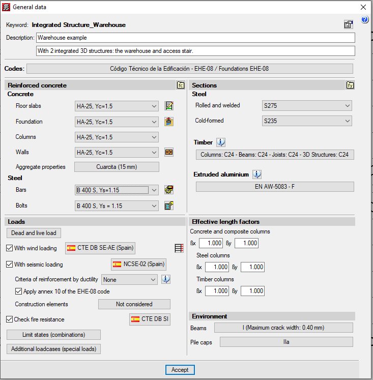
With CYPECAD, users have complete control over the general data that will determine the analysis and modelling of the structure they wish to enter:
- Selection of standards to apply
- Material selection
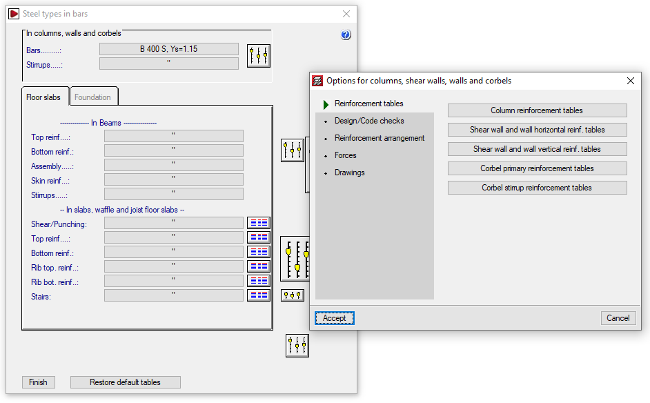
- Design options and reinforcement tables
- Load definition
Dead loads, live loads, wind, seismic loading, fire resistance checks, additional loadcases. - Column buckling coefficients
- Conditions for beams and pile caps
Structure geometry
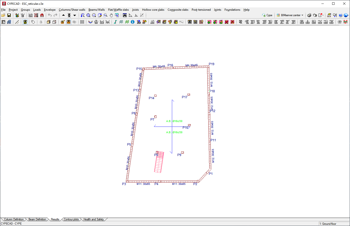
When introducing structures in CYPECAD, several of the methods outlined below can be combined accordingly. The choice of procedure will depend on users’ preferences, the way they receive project data, or the element or information being introduced.
- Manual insertion using global or relative coordinates
This can be combined with all other introduction methods at any time. - Manual insertion assisted by DXF and DWG files used as templates
This can be combined with all other introduction methods at any time. - Automatic insertion by importing a CYPE 3D structure
This can be combined with all other introduction methods at any time. - Automatic insertion by interpreting DXF or DWG file information
This is an initiating procedure. It can be combined with all other procedures except for importing files in IFC format and connecting to the BIM model. - Automatic insertion by importing files in IFC format, generated with CAD/BIM programs
This is a launching procedure. It can be combined with all other procedures except for DXF or DWG file interpretation and connection to the BIM model. - Importing data using by linking to an Open BIM model
This is a launching procedure. It can be combined with all other procedures except for DXF or DWG file interpretation and connection to the BIM model.
This versatility adds speed, reliability, and efficiency to the process of introducing a structure.
Analysed structural elements
Supports
The structural supports that CYPECAD analyses and designs are:
- Columns
- Reinforced concrete columns
Rectangular, circular, and polygonal section.
More information - Steel columns
Rolled, reinforced and cold-formed steel columns.
More information - Composite steel and concrete columns
Embedded concrete-cased sections or closed concrete-filled sections
More information - Timber columns
Rectangular or circular-section timber columns
More information
- Reinforced concrete columns
- Shear walls
More information
- Rectangular
- Any geometric shape composed of rectangles
- Rectangular
- Walls
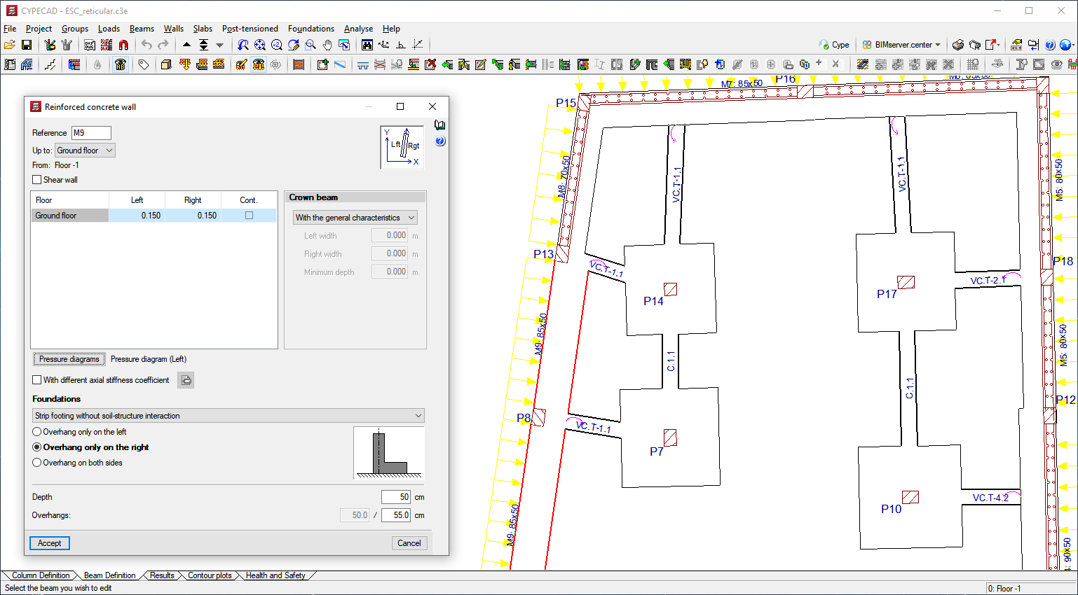
- Reinforced concrete walls
- Plane stress walls
More information - Generic masonry walls
- Concrete block walls
These walls can be designed with or without reinforcement. Users can indicate the dimensions of the blocks or use blocks designed by manufacturers such as the Spanish company NORMABLOC which designs concrete blocks and masonry.
Some walls may contain openings. The program analyses the necessary reinforcement for the openings in the reinforced concrete walls (lintel, sills, lateral and diagonal walls) and the lintel reinforcement if there are openings in concrete block walls. Additionally, users can obtain reports of the checks that have been carried out during the reinforcement design process, which can be viewed on-screen and printed out.
The crown beam is also designed for all types of walls as is the intermediate beam at floor level in the case of generic masonry walls and concrete block walls.
- Reinforced concrete walls


Beams
Floor slabs may be composed of reinforced concrete, steel (normal or castellated), composite and timber. Corbels can also be introduced.
- Concrete beams
More information - Steel and composite beams
More information - Timber beams
More information

Slabs
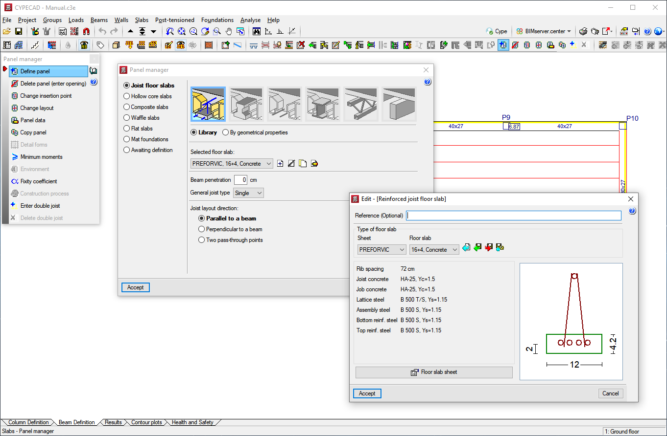
The following types of slabs can be designed in CYPECAD:
- One-way
- Concrete joists
- Reinforced precast
- Precast prestressed
- Reinforced in-situ
- Post-tensioned in-situ
- Steel joists
- Timber joists
More information - Steel lattice
- Concrete joists
- Flat slabs
- Reinforced
More information - Post-tensioned
More information
- Reinforced
- Waffle slabs
- Reinforced
- Post-tensioned
More information
- Hollow-core slab
More information - Composite slabs (steel deck)
More information
CYPECAD allows users to check the ultimate limit state for punching shear of waffle and flat slabs, and mat foundations using two methods: point tangential stress tests and in accordance with design code criteria.
More information on Punching shear verification.

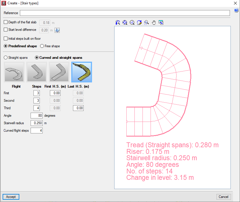
Stairs
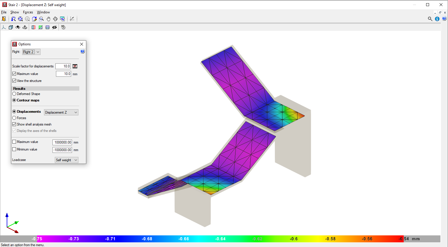
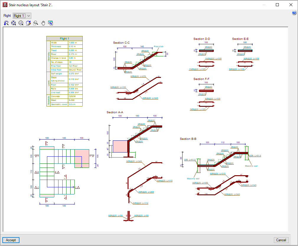
CYPECAD analyses and designs straight and curved stair slab reinforcement as isolated elements of the structures. The program establishes the reactions on the main structure based on geometry, type, and arrangement of the supports, and applied gravitational loads, which are then applied as line and surface loads (for the steps built on the floor) in the dead and live load loadcases.
The program designs stairs using the finite element method, using the two usual loadcases when designing stairs: permanent loading and live loading.
CYPECAD displays the reinforcement of each span of the stairwell on screen. It is also possible to view the displacements, forces, and deformed shape of each span in 3D.
Foundation
The foundations designed by CYPECAD can be: fixed (with footings or pile caps) or floating (with mat foundations and foundation beams, where users have to define the subgrade modulus when applying the Winkler theory).
Additionally, the program allows users to analyse the foundations alone (without inserting a superstructure) by defining column starts.
- Pad footings
These can consist of reinforced concrete or mass concrete, be for a single or combined for multiple supports (columns, shear walls and walls), which can be placed freely on the foundation element. - Pile caps
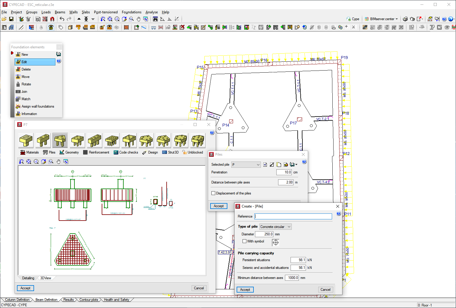
They can hold a number of supports (columns, shear walls and walls), and can be placed freely on the foundation element.
A wide range of types are available:
- Rectangular pile caps for one, two, four and five piles
- Triangular pile caps for three piles
- Strip pile caps for three to thirty piles
- Rectangular pile caps for multiple piles (grid distribution from three to thirty piles per side)
- Pentagonal pile caps for five or six piles
- Hexagonal pile caps for six or seven piles
- Strap beams and tie beams
Act on footings and pile caps. - Mat foundations and foundation beams
The mat foundations and foundation beams are considered to be supported on an elastic foundation (ballast coefficient method), according to the Winkler model, based on a constant of proportions between forces and displacements, the value of which is the ballast coefficient.
Foundation beams and mat foundations are part of the overall structure and therefore interact with the rest of the structure (they are part of the overall stiffness matrix of the structure). Therefore, loads can be applied to these elements, as well as to any beam or slab of the structure they are part of.
The limit states to be checked are those applicable to the design of reinforced concrete elements (ultimate limit states), and force, equilibrium, and uplift checks (serviceability limit states).
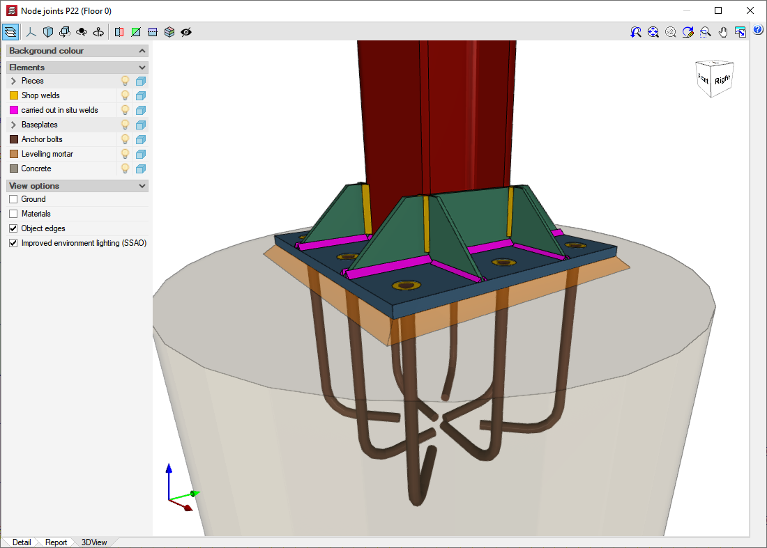
CYPECAD carries out checks for shear and punching shear in mat foundations and foundation beams. - Base plate
For any steel column arrangement (simple and composite sections).

More information at:
- Foundation analysis and design
General description. - Footing analysis and design
Includes references to strap and tie beams. - Pile cap analysis and design
Includes references to strap and tie beams. - Advanced design of surface foundations
This module complements the analysis and design of footings and pile caps. - Punching shear verification in CYPECAD
In waffle slabs, flat slabs, and mat foundations. - Baseplates
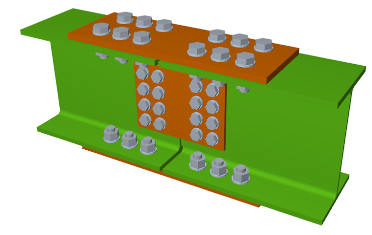
Welded and bolted joints
CYPECAD and CYPE 3D have five modules for analysing and designing steel-section joints.
- Joints I. Welded. Warehouses with rolled and welded steel I-sections
More information - Joints II. Bolted. Warehouses with rolled and welded steel I-sections
More information - Joints III. Welded – Building frames with rolled and welded steel I-sections
More information - Joints IV. Bolted. Building frames with rolled and welded steel I-sections
More information - Joints V. Flat trusses with hollow structural sections
More information


The Joints I, Joints II and Joints V modules have a wider field of application in warehouses designed using CYPE 3D and with Integrated 3D Structures of CYPECAD, while the type of joints designed by the Joints III and Joints IV modules have a wider field of application in building structures made up of frames that are designed in CYPECAD.
In any case, the Joints I, Joints II, Joints III and Joints IV modules have common types of joints that are developed and completed in the same way in each module.
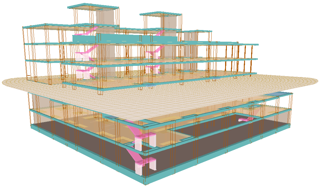
Design load analysis
The design load analysis is carried out by means of a 3D spatial analysis using stiffness matrix methods, which contains all the elements that define the structure: columns, reinforced concrete shear walls, walls, beams, and slabs.
The deformation compatibility of all nodes is established, considering 6 degrees of freedom, and the non-deformability hypothesis of the plane of each floor is created to simulate the rigid behaviour of the floor slab, preventing relative displacements between nodes of the slab (rigid diaphragm). Therefore, each floor can only rotate and move as a whole (3 degrees of freedom).
The consideration of rigid diaphragm for each independent area of a floor is preserved even if beams, not floor slabs, are defined on the floor, except for unconnected beams that users disconnect from the rigid diaphragm and except for walls that are not in contact with floor slabs (from v.2012.a onwards). More information can be found on the "Rigid diaphragm at floor level in CYPECAD" web page.
When there are independent areas on the same floor, each of these is regarded as a separate part in terms of the non-deformability of that area and shall not be considered as a whole. Therefore, the floors will act as independent non-deformable planes. A non-connected column is considered as an independent area.
For all load states, a static analysis is carried out (except when dynamic actions due to seismic activity are considered, in which case the spectral modal analysis is used) where a linear behaviour of the materials is assumed and, therefore, the first-order analysis, in order to obtain displacements and stresses.
Integrated 3D structures always have 6 degrees of freedom per node. More information on integrated 3D structures.
Stairs also have 6 degrees of freedom and are developed and completed separately. The program determines the reactions on the main structure, which are translated as linear and surface loads (in the case of steps built on the floor) in the dead load and live load loadcases. More information on stairs.
Detailed information on this aspect can be found in the "CYPECAD – Calculations manual”. The manual can be accessed from the main menu of the CYPE programs or from the CYPECAD "Help" drop-down menu.
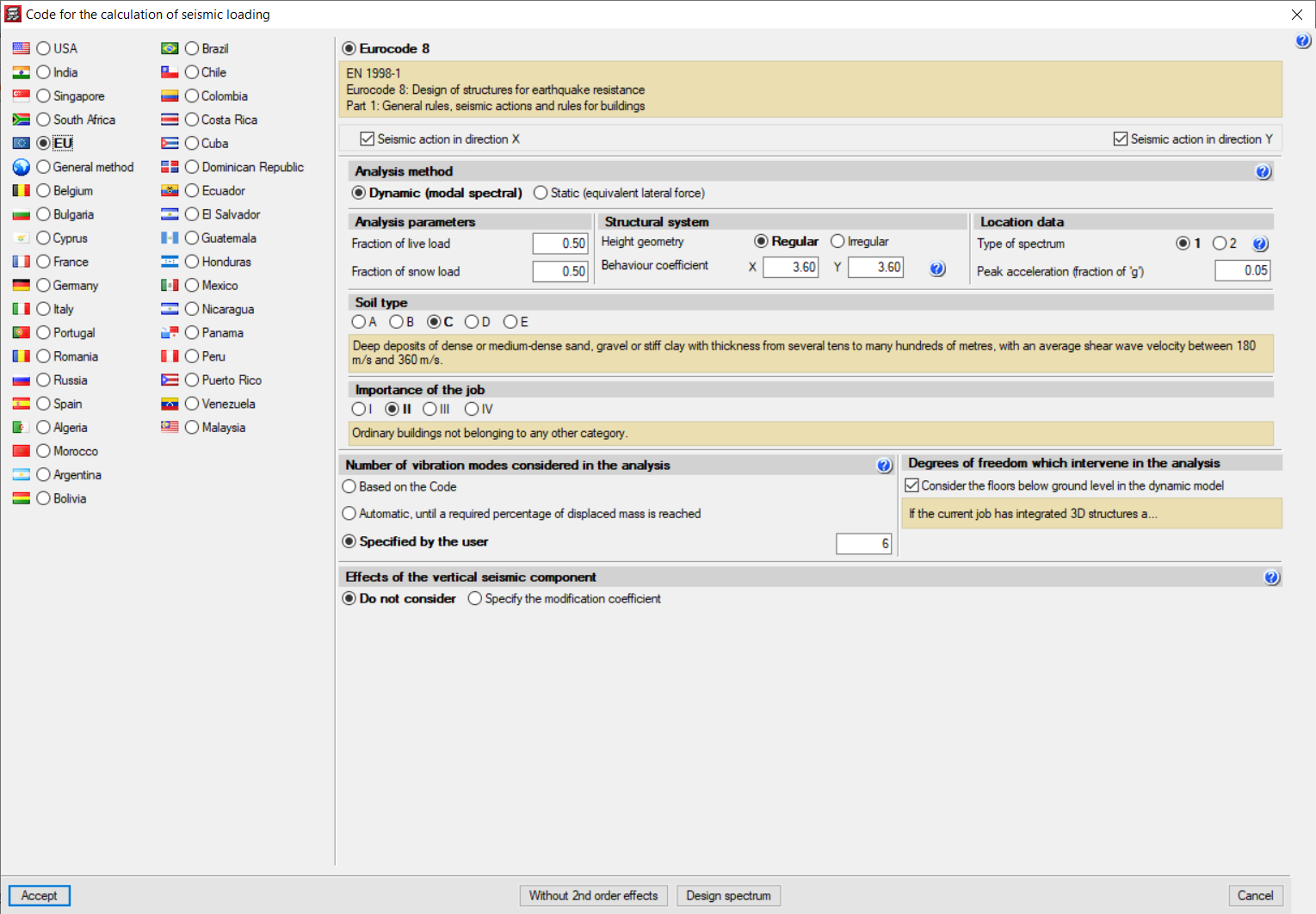
Seismic analysis
The seismic analysis is carried out by means of a complete modal spectral analysis which resolves each mode as a loadcase and carries out the modal expansion and the modal combination to obtain the forces.
More information at CYPECAD. Seismic analysis:
- Effect of non-structural construction elements on buildings’ seismic behaviour
- Seismic design criteria by capacity for supports and concrete beams
- Base shear correction
- Fundamental period of the structure with user value
- User-specified seismic spectrum
Detailed information on the seismic analyses is also available in the "CYPECAD – Calculation report" manual, which can be accessed from the main CYPE program menu or from the CYPECAD "Help" drop-down menu.
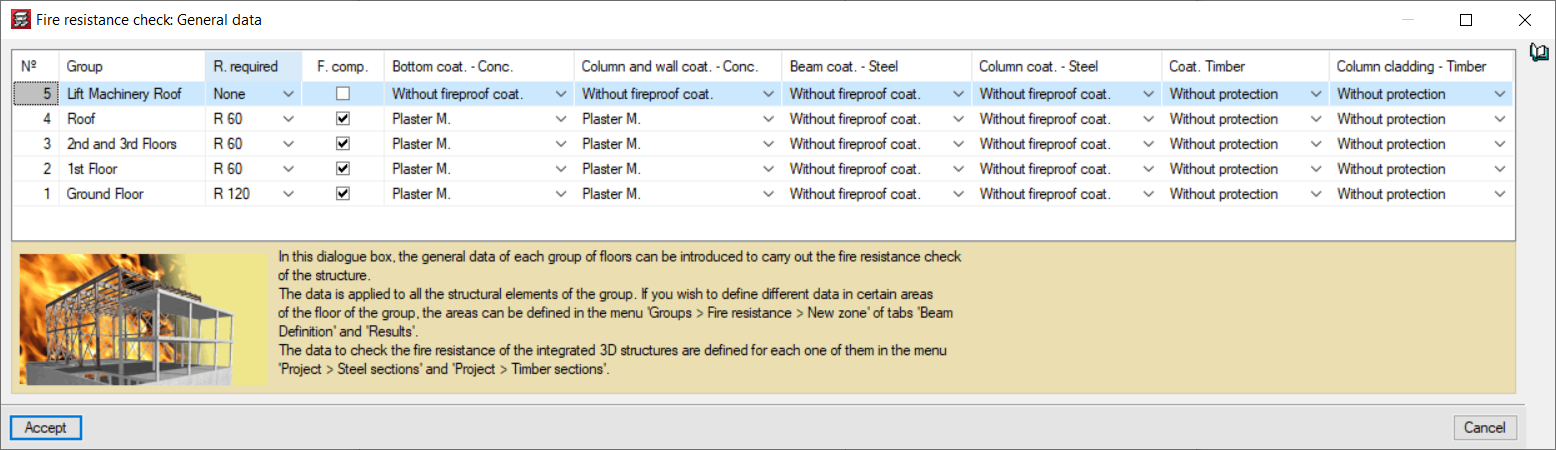
Fire resistance check
With the “Fire resistance check module”, CYPECAD and CYPE 3D carry out the following:
- For steel and concrete structural elements
Fire resistance checks and the design of protective coatings in accordance with the selected code. - For timber sections
Fire resistance checks and the design of timber sections against fire action, so they comply with the selected code.
More information on Fire resistance checks.
Results analysis
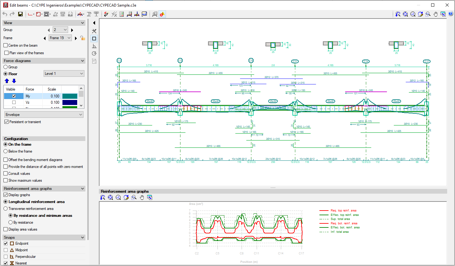
Beam editor
The beam editor displays the information of a frame and automatically updates it with the changes made. It provides quick and easy graphical editing (reinforcement, steel sections, solid sections, trusses, connectors, etc.). Users can obtain:
- Detailed U.L.S (Ultimate Limit State) and S.L.S (Serviceability Limit State) check reports for concrete beams (with checks for failure due to torsional stress and design criteria for seismic loads)
- U.L.S and S.L.S. reports for steel beams
- Required and effective reinforcement area graphs
- Bar bending diagrams and reinforcement configuration options on the frame drawings
- Horizontal and vertical openings in concrete beams
- Rectangular variable-section dropped beams
More information on Beam editors in CYPECAD.
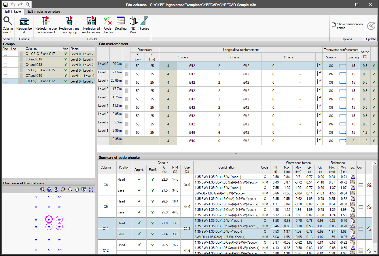
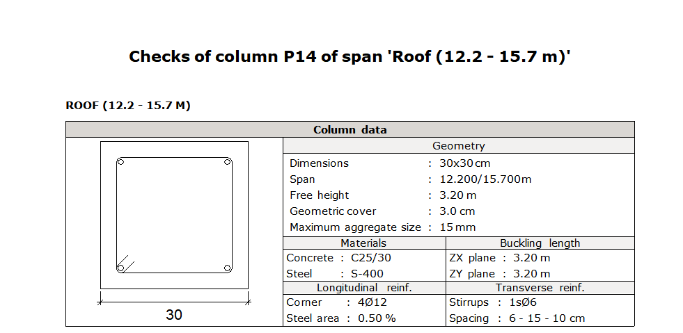
Column editor
CYPECAD has a column reinforcement editor that:
- Shows all data related to their design and verification and generates detailed reports of the ultimate limit state (U.L.S.) checks that are carried out.
- Allows users to organise column schedule groups.
- Checks any modifications that have been undertaken.
- Redesigns reinforced concrete and steel columns.
More information on Column editors in CYPECAD.
Other results analysis tools
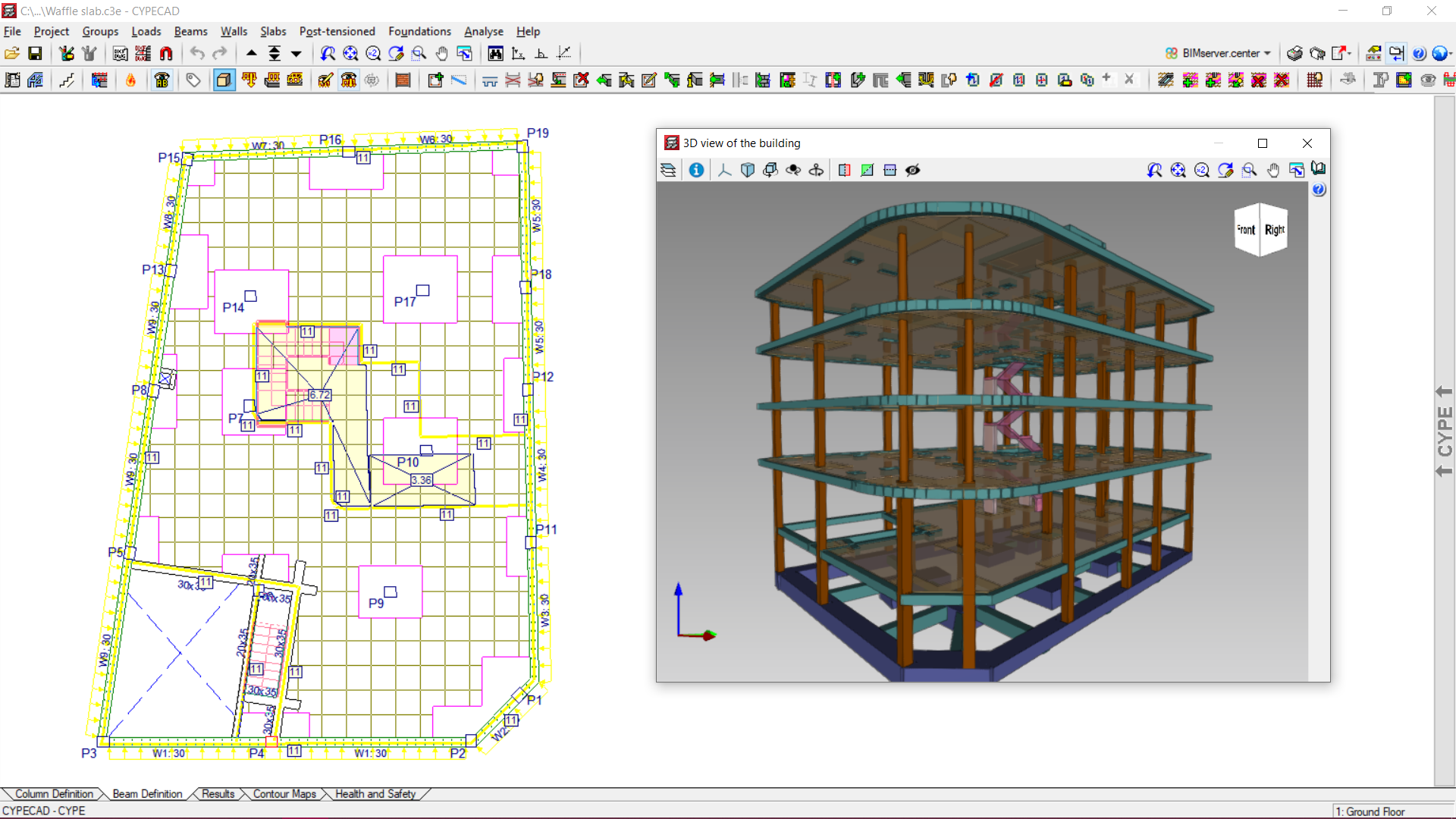
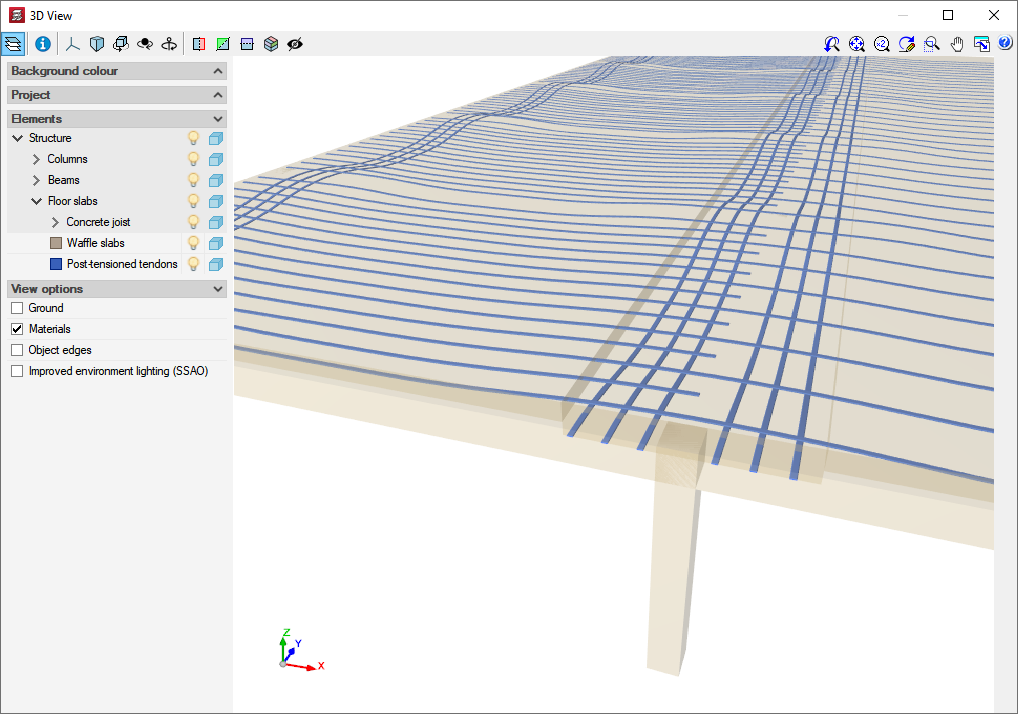
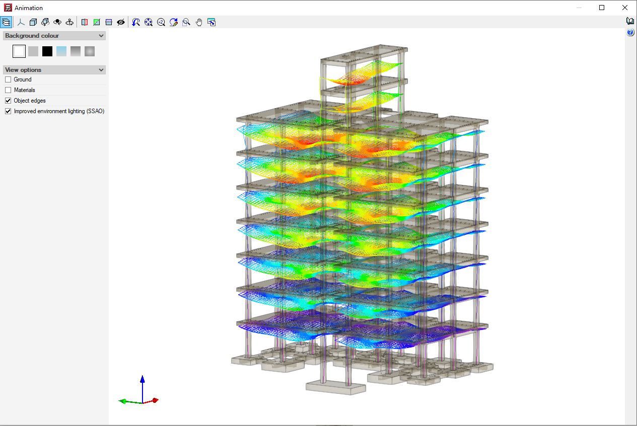
CYPECAD has a number of tools that allow users to check all graphic results on-screen.
After the analysis, users can view the deformed shape of the structure in 3D (with colour scales), produced by simple loadcases or a combination of loadcases. Users can also see an animated view of the deformation process that the selected loadcase combination produces.
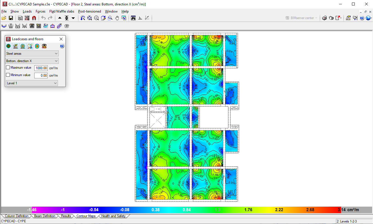
Displacements, forces, force combinations and quantities of flat slabs, foundation slabs and waffle slabs can be represented on contour plots (coloured graphs where each colour represents a value) and on contour line diagrams (curves connecting geometric points with the same value).
It also provides graphical consultation of stress envelopes, deflections, etc.
Users can modify the reinforcement of all the elements and then check the modifications for footings, pile caps, beams, columns, and joist slabs.
It can automatically match top reinforcement in joist slabs, taking into account length criteria or steel area and length criteria. This way, more uniform reinforcement layouts are obtained, aiding in the construction process.
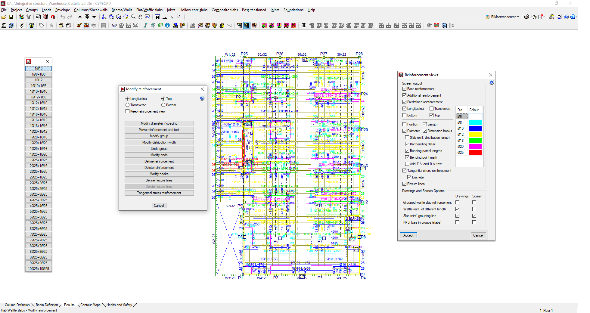
It modifies the reinforcement of waffle slabs and slabs by means of visible tables. Users can copy the reinforcement from one floor to another, modify the geometry after the analysis and insert reinforcement without having to re-launch the analysis.
The editor for footings, pile caps, baseplates, and strap and tie beams is an extremely powerful tool that allows users to verify any geometric and reinforcement configurations they have defined. The program provides reports containing all the checks that have been carried out on the foundations and their level of compliance. It is possible to match the geometry, typology and reinforcement of footings, pile caps, strap beams, tie beams and baseplates. More information on foundations.
Reports
Drawings
Project plans can be configured in different paper formats and sizes, either standard or user-defined. Furthermore, they can also be drawn by printer, plotter or exported to DXF and DWG format. In the floor drawings, the DXF or DWG files that have been used to define the job can be included. They can be integrated entirely or only the desired layers, such as stairs, for example.
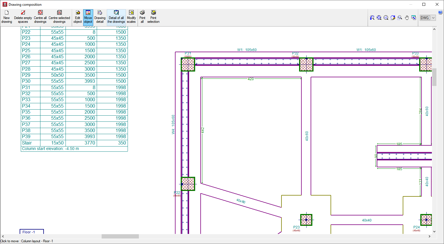
A drawing editor is available on the job's own floors, which provides users with a wide range of resources: adding dimensions, texts, sections of the building, construction details in DXF format, floor slab sections, modifying the location of texts, etc. These modifications are saved with the project.
CYPECAD has an extensive library of steel, concrete, composite and inclined slab construction details available to be incorporated into any of the drawings generated by the program.
You can apply any scale, line thickness, font size, title block, etc. This way, the drawing of the plan can be completely customised.
CYPECAD provides complete and clear drawings. You can obtain drawings of the layout, floor plan, foundations, beams, column schedule, detailing of columns and shear walls, foundation loads, wall elevations, stair detailing, loads, corbels, etc. They optionally include measurement tables and reinforcement details. These can be configured so that each user can obtain the drawings according to their needs. CYPECAD has an editor that allows text to be moved while viewing the drawings on screen.
Reports
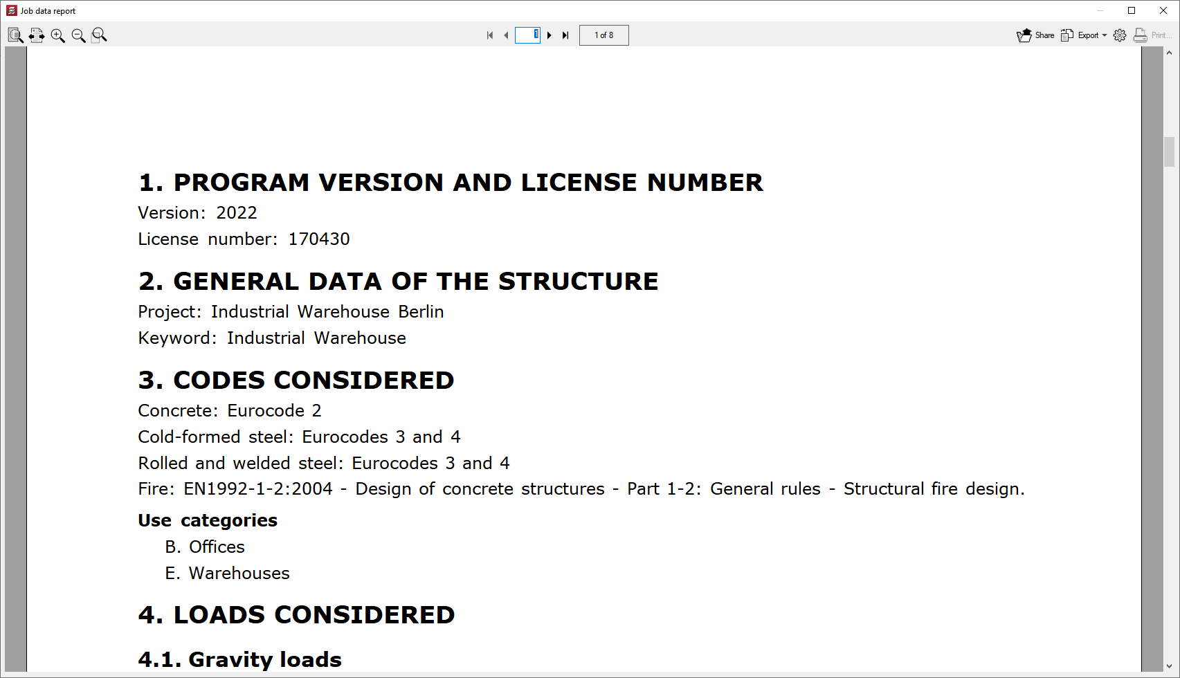
Users can easily obtain reports of all the data entered and the results: list of project data, combinations used in the analysis, foundations, corbels, envelopes, reinforcement and quantities of all the elements, job ratios, horizontal wind loads, participation coefficients (seismic loads), second order effects, etc.
All this can be obtained either on screen or by printer, but files can also be created in HTML, DXF, DWG, RTF, PDF formats, etc.
The reports that are generated include the following:
Detailed ultimate limit state check reports
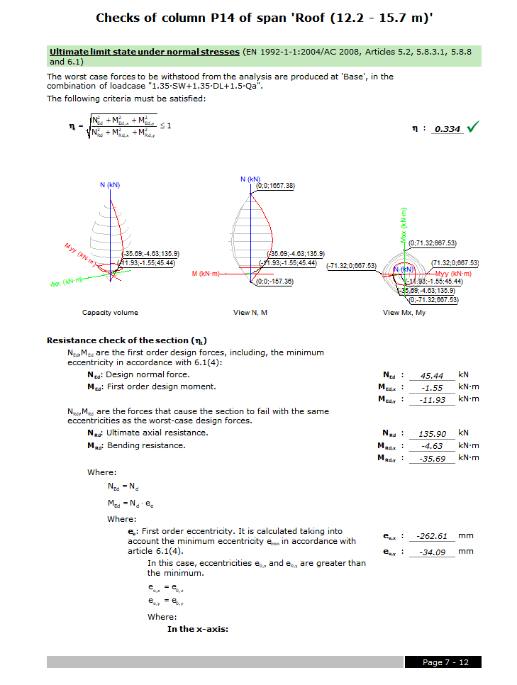
CYPECAD, CYPE 3D and the Portal frame generator generate detailed ultimate limit state (U.L.S.) check reports. The U.L.S. reports contain all the checks these programs carry out to design concrete, steel, aluminium and timber elements. Each check refers to the design code and article requiring the check, or the criteria which have been applied to carry it out. The detailed contents of the U.L.S. reports make these essential documents with which users can verify, justify and optimise the design of the structural elements that have been analysed.
The level of detail of these reports also acts as a guide allowing users to know all the checks to which the structural element is submitted.
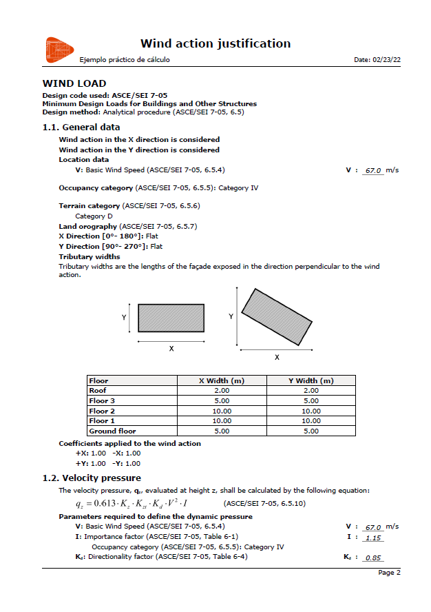
Wind action justification report
CYPECAD also generates wind action justification reports. By selecting the image below, a PDF showing an example of this report can be downloaded.
More CYPECAD features
Collective protection systems
The "Collective protection systems" module allows users to generate drawings and bills of quantities for the collective protection systems of a CYPECAD job.
There are two ways of generating this information:
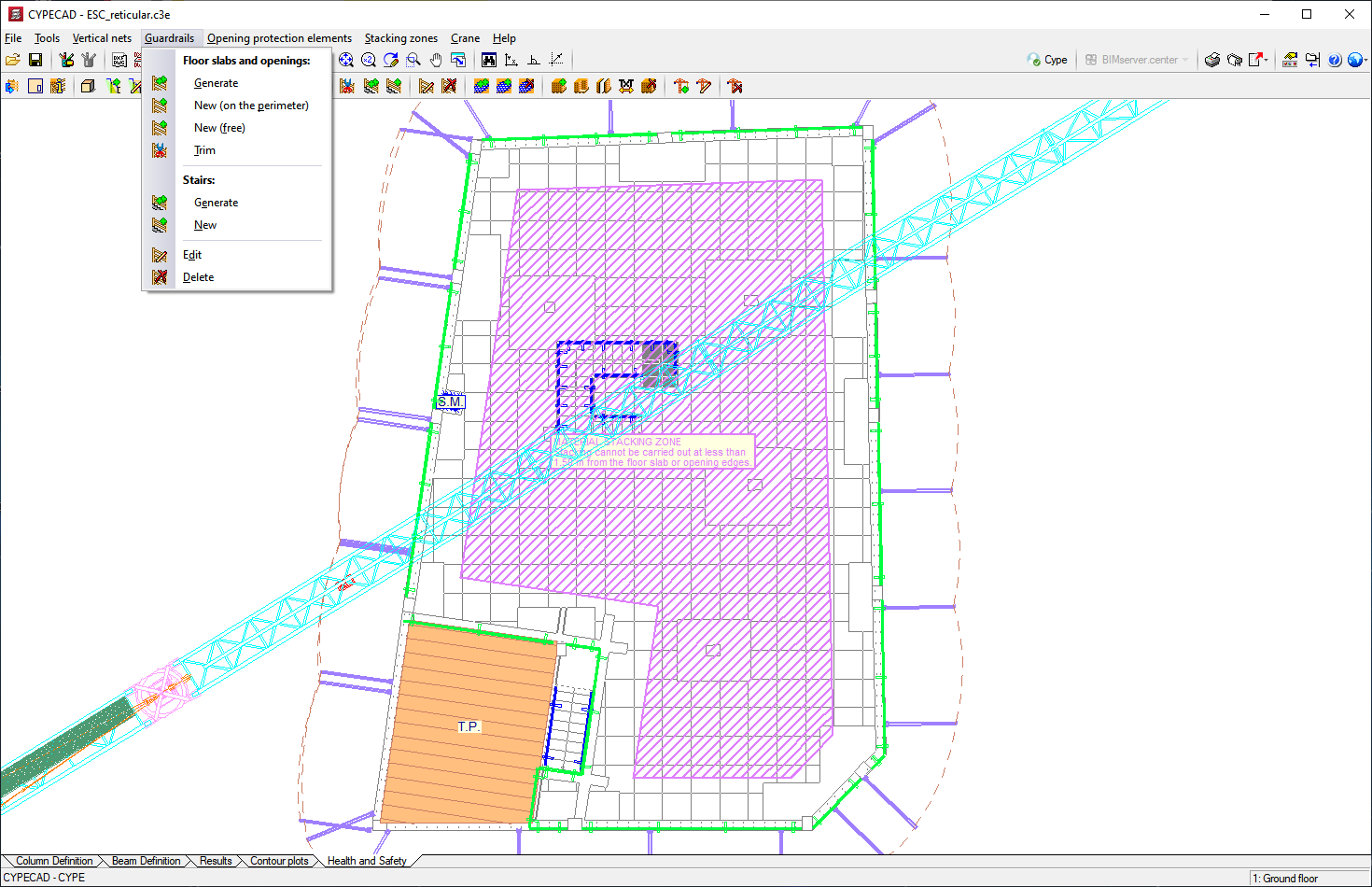
- CYPECAD Health and safety tab
In this tab (located in the top part of the CYPECAD window), users can find tools allowing them to enter the information necessary for generating the drawings and the bill of quantities of the collective protection systems.
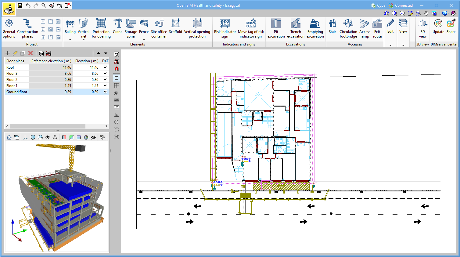
More information - CYPE Health and safety program
Program created to assist users with the preparation of drawings of collective protection systems so that they can be incorporated into the Health and Safety Project and generate their bill of quantities.
Unlike the tool located in the CYPECAD "Health and Safety" tab, this program is integrated in the Open BIM workflow and therefore includes the information it generates.
More information
Exports
Exporting in IFC format
CYPECAD allows all the designed structural elements to be exported in IFC format (Industry Foundation Classes - versions 2x3 or 4).
As well as being the format by which all the programs included in the Open BIM workflow exchange information, CYPECAD also generates files in IFC format without being linked to an Open BIM project to generate these files so that the information generated in CYPECAD can be read in CAD/BIM programs such as Allplan®, Archicad®, Revit® Architecture, etc.
This connection mode with other CAD/BIM software loses some of the considerable advantages of the Open BIM workflow, but it is another feature that has been available in CYPECAD since earlier versions.
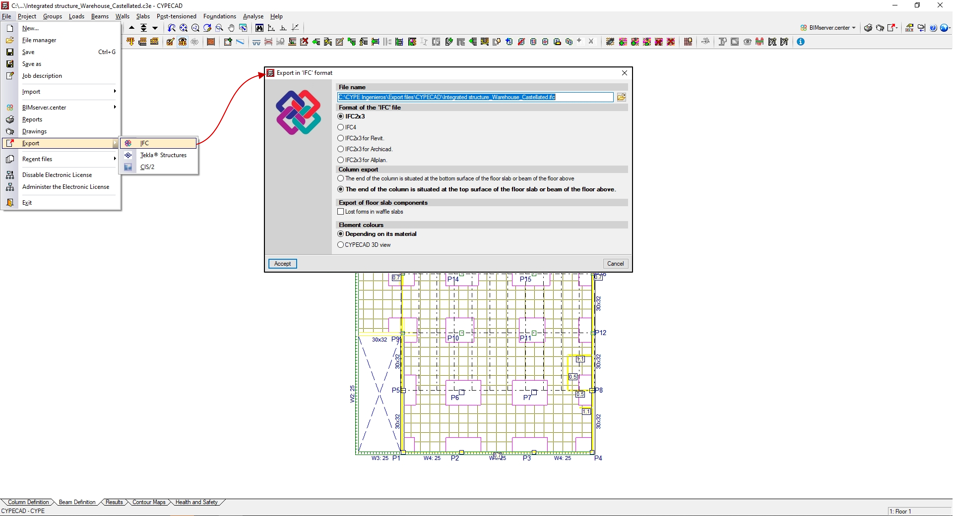
In order to carry out these exports, CYPECAD has the "Export in IFC format" option (File menu > Export).
The "Export in IFC format" dialogue box (File menu > Export > IFC) allows users to choose different variations of the IFC format to generate the export file:
- IFC 2x3
- IFC4
- IFC 2x3 for Revit (versions 2012, 2013 and 2014)
- IFC 2x3 for Archicad
- IFC 2x3 Allplan (version 2014 and earlier)
CYPECAD exports the following elements to IFC format:
- In one-way slabs
- Reinforced joists
- In situ joists
- Steel joists
- Open-web joists
- Forms
- In composite slabs
- Slab plates
- Concrete layer
- In post-tensioned slabs
- Tendons
CYPECAD also allows IFC format files generated by CAD/BIM programs to be imported, thanks to its Automatic job introduction module: DXF, DWG and CAD/BIM models. More information at the CYPECAD Introducing the structure website.
In order for CYPECAD to export the work in IFC format, the user license does not need to have the "Automatic job introduction: DXF, DWG and CAD/BIM models" module.
Analysis using multiprocessors
CYPECAD and CYPE 3D use the potential offered by multiprocessors in the analysis of their structures.
To access these features, CYPECAD and CYPE 3D have the common module Parallel analysis with up to eight processors, which saves a substantial amount of analysis time.

Codes included in the user license
Depending on the country from which the licensee acquires the license, only the code implemented in each program is activated for working in that country.
More information on this aspect and on the possibility of acquiring codes not initially included is available on the Design codes implemented in the user license webpage.
CYPECAD versions and modules
CYPECAD versions
CYPECAD is available in its unlimited version and also in two limited versions called LT30 and LT50, which contain the same tools and module acquisition possibilities, but have the following conditions:
CYPECAD LT50:
- Fifty columns
- Four floor groups (Floor group: floors which are the same and consecutive)
- Total of five floors
- Walls: one hundred linear metres
CYPECAD LT30:
- Thirty columns
- Four floor groups (Floor group: floors which are the same and consecutive)
- Total of five floors
- Walls: one hundred linear metres
Integrated 3D structures of CYPECAD (also LT50 and LT30) is not technically a module. To define these 3D structures in CYPECAD, users must also have the required permits to use CYPE 3D in their user license and, optionally, modules that are exclusive to CYPE 3D.
Other features
CYPECAD modules
In order to access further features offered by the program, there are several modules that can be found on the “CYPECAD modules” webpage.
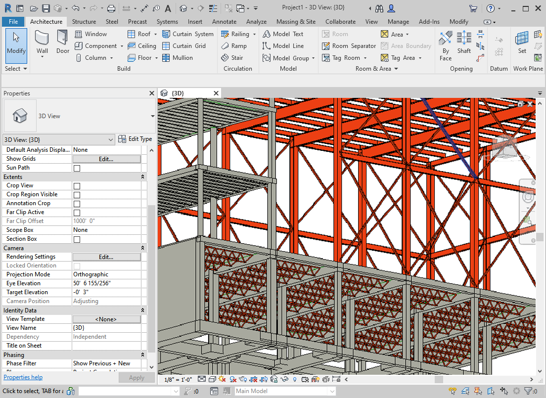
Interoperability with other systems
CYPECAD, 3D structures integrated into CYPECAD, and CYPE 3D can export the analysed and designed structure to TEKLA Structures. More information on export options can be found at How to export from CYPE to TEKLA® Structures?