

Advanced design of surface foundations
The "Advanced design of surface foundations" module complements the Footings and Pile caps modules when these are used in CYPECAD. Allows for the design of foundations with footings and pile caps with special element intersections (strap and tie beam intersections), geometry trimming of footings, and application of line, point and surface loads on footings, pile caps and strap and tie beams. In the case of CYPE 3D, this module only allows for trimming of the footing geometry to be carried out.
Polygonal limits for footings (in CYPECAD and CYPE 3D)
Using the Advanced design of surface foundations module in CYPECAD or CYPE 3D, the user can define limits or boundaries which cannot be invaded by reinforced concrete or mass concrete footings. Examples of these limits or boundaries may include property limits or zones reserved for other uses such as deposits, lift shafts etc. These limits may also be defined for the program to define irregular polygonal footings for any other reason, regardless of whether there are real physical limits.
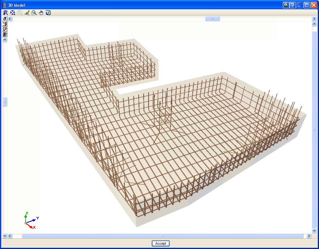
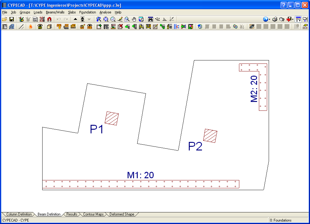
The user has to enter polylines to define the limits. When the program designs the foundations, it automatically trims the footings which pass or invade the established limits. The fraction of the footing in which the column starts or columns remain is conserved and is, therefore, what is considered in the analysis. During the design of the footings, the program does not allow the established limits to be exceeded. The design of a footing may be affected by more than one limit.
The limits are entered in CYPECAD using the Limits for polygonal footings option located in the Foundations menu within the "Column definition" or "Results" tab. In CYPE 3D, this option is available within the Foundations tab > Limits> New. The limits may be entered manually by defining each edge in both programs or by snapping to a DXF/DWG template. In CYPECAD, the limits that have been entered in a group, only affect the footings of that group, whilst for CYPE 3D, the limits affect all the footings regardless of their elevation.
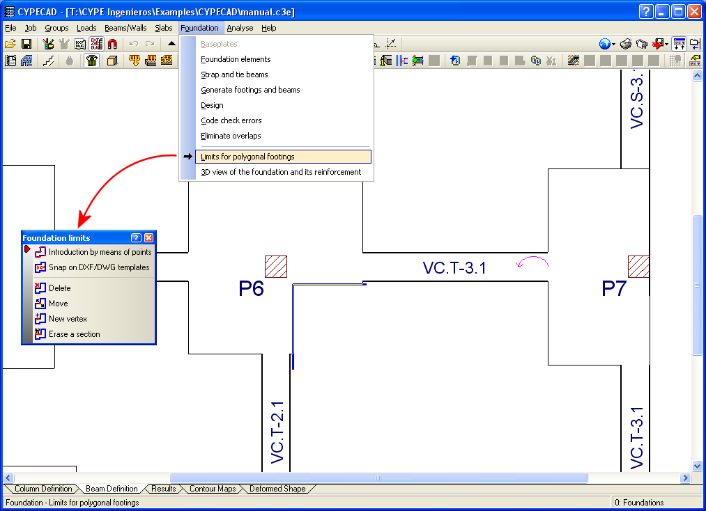
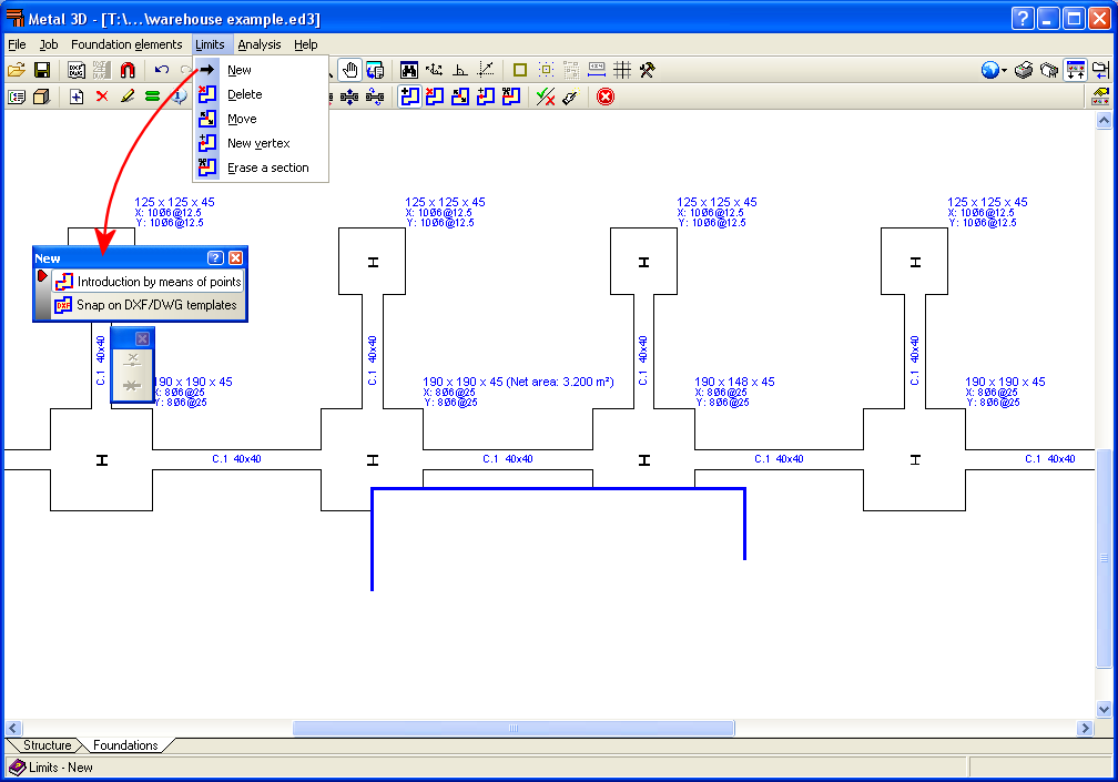
Once the polylines defining the limits have been entered, the user may delete or move them, insert a new vertex or eliminate a section of the polyline.
These polylines have certain logical restrictions regarding their position:
- They cannot intersect a column.
- They must cut the outlines of the footings before and after their design.
- Footings with multiple columns cannot be trimmed in such a way as to leave one column isolated from the rest of the columns or column starts sharing the footing.
- The defined limits have no effect on strap and tie beams, pile caps, tapered footings or strip footings. They only affect reinforced concrete and mass concrete footings of constant depth. Nonetheless, CYPECAD allows for its users to define a combined footing of constant depth, containing several supports which may also include a wall or shear wall (defined with external fixity and without a footing), and in this case, the limits will affect the footing.
If a polyline does not comply with one of these conditions, the program will not consider the limit generated by the polyline. In this case, an explanation of why it has not been possible to adapt the footing outline to the entered limits is provided in the check report of each affected footing.
The reasons may include:
- The limit that has been entered cuts through a column.
- The limit that has been entered intersects the footing but does not divide it.
- The limit lies completely within the inside of the footing.
- As there are no reinforcement starts present at the footing, the effective outline cannot be calculated.
- The limit divides the footing without the reinforcement starts lying in a single part of the footing.
- Tapered footings are not affected by the entered limits.
The footing check reports can be visualised using different options:
In CYPECAD:
- Beam Definition or Results tab > Foundation > Code check errors > Select footing
- Beam Definition or Results tab > Foundation > Foundation elements > Edit icon > Select footing > Code checks button or Design button.
In CYPE 3D:
- Foundation tab > Analysis > Check > Select footing
- Foundation tab > Foundation elements > Select footing > Check button or Design button.
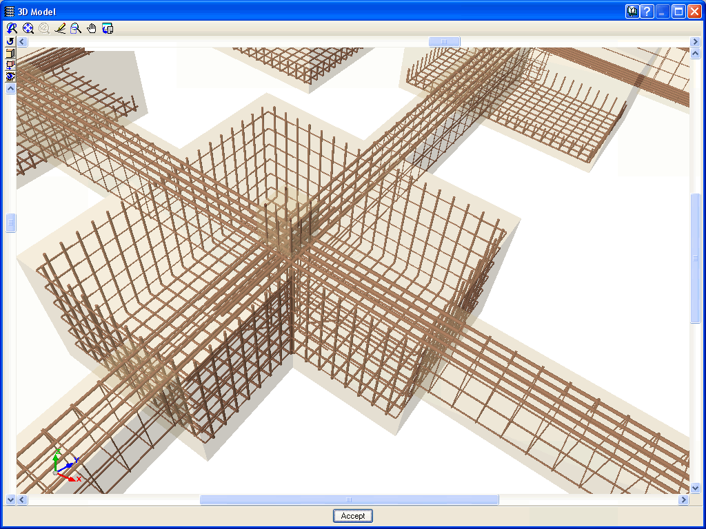
Strap and tie beam intersections (only for CYPECAD)
Using the Advanced design of surface foundations module, CYPECAD can design foundations consisting of footings or pile caps with intersecting strap and tie beams.
Loads applied on footings, pile caps and, strap and tie beams (only for CYPECAD)
Using the Advanced design of surface foundations module, CYPECAD allows users to enter point, line and surface loads on footings, pile caps and, strap and tie beams, and consider them in the design. Using this module, CYPECAD also recognises the loads transmitted by the stair supports resting on the aforementioned foundation elements.
CYPECAD assumes that the soil below the strap and tie beams does not intervene in the force equilibrium or distribution to which they are submitted. Therefore, strap and tie beams are designed to also support any loads that may be present acting on them and will transmit the forces to the footings or pile caps at their ends, or other strap and tie beams they may intersect.
Other features
To access further features offered by the program, several modules can be found on the “CYPECAD modules” and “CYPE 3D modules” web pages.