
Automatic job entry: DXF, DWG and CAD/BIM models
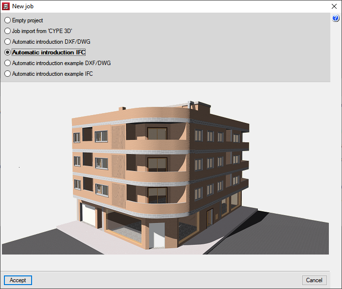
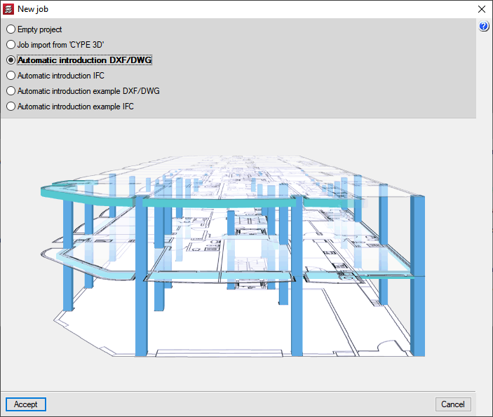
CYPECAD's Automatic entry module has two options available that have been created to automatically generate the structure:
- Import of IFC files from CAD/BIM programs
- Interpretation of DXF and DWG files
In both cases, the structure is generated automatically after the use of an assistant which prompts the user to confirm or complete data contained in these files.
Import of IFC files from CAD/BIM programs
Using the Automatic entry IFC option, the Automatic entry module allows users to import IFC files generated by the main CAD/BIM programs (Allplan®, Archicad®, Revit® Architecture) to CYPECAD. Using an assistant, the user confirms and completes the information obtained from the IFC file, after which, the following elements of the structure are generated:
- Floor distributions
- Loads on floors
- Columns
- External perimeter and internal openings perimeter beams
- Foundation
- Partition and façade wall line loads
- Drawing templates for each floor
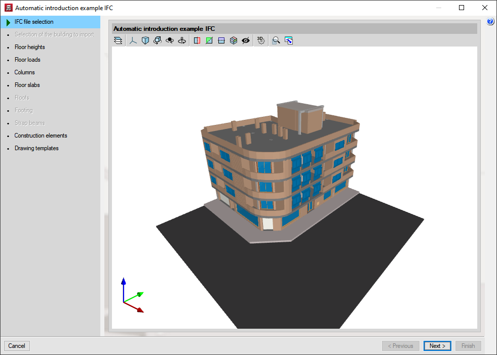
The Automatic entry IFC assistant contains a series of dialogue boxes where data is displayed or is to be filled in, which will automatically generate the job.
IFC file selection
In this dialogue box, the user indicates where the IFC file is located, which will then be used by the program to import the data displayed in the following steps of the automatic entry.
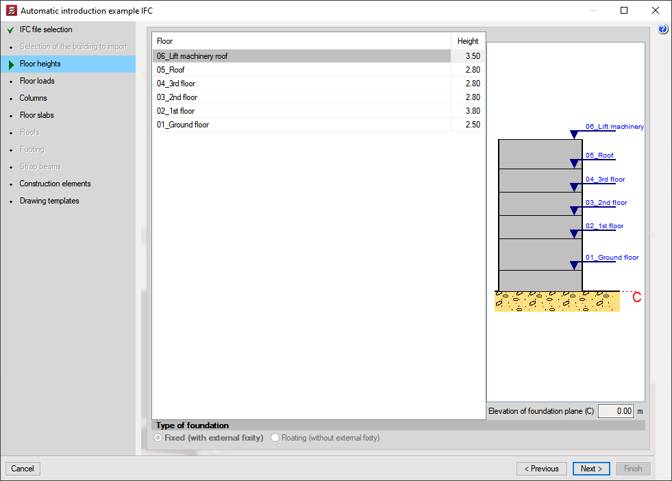
Floor heights
In this section, the heights of all the floors contained in the selected IFC file are defined. CYPECAD proposes the heights and names of the floors contained in the IFC file. The user may confirm or modify this data. The type of foundation the job is to have is also indicated here: Fixed (with external fixity) or Floating (without external fixity) and the elevation of the foundation plane.
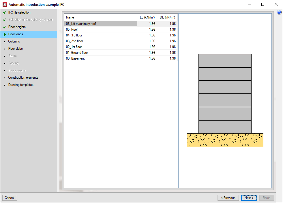
Floor loads
Here, the user indicates the dead and live loads of the floors contained in the selected IFC file.
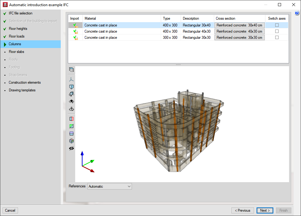
Columns
A list of column-type elements (IFCCOLUMN entity) in this dialogue box is displayed in the IFC file. The user activates those to be imported to generate the structural column of the job.
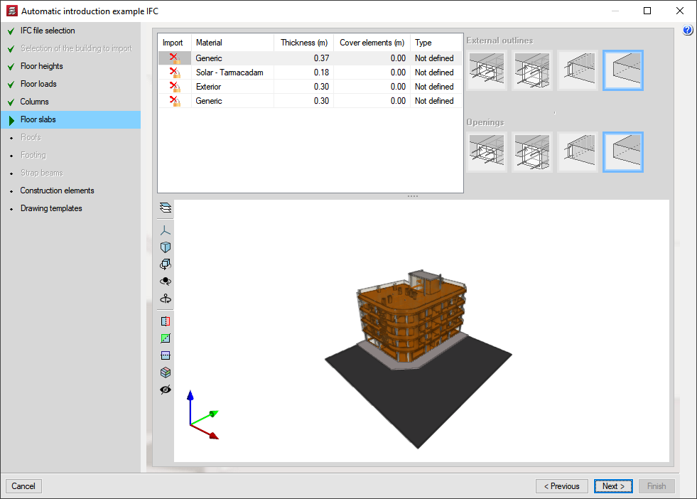
Floor slabs
In this dialogue box, a list of floor slab and roof elements (IFCSLAB and IFCROOF entities) contained in the IFC file is displayed. The user activates the slab and roof types for which CYPECAD is to define their external perimeters and internal opening perimeters. The beam defining these perimeters must also be defined.
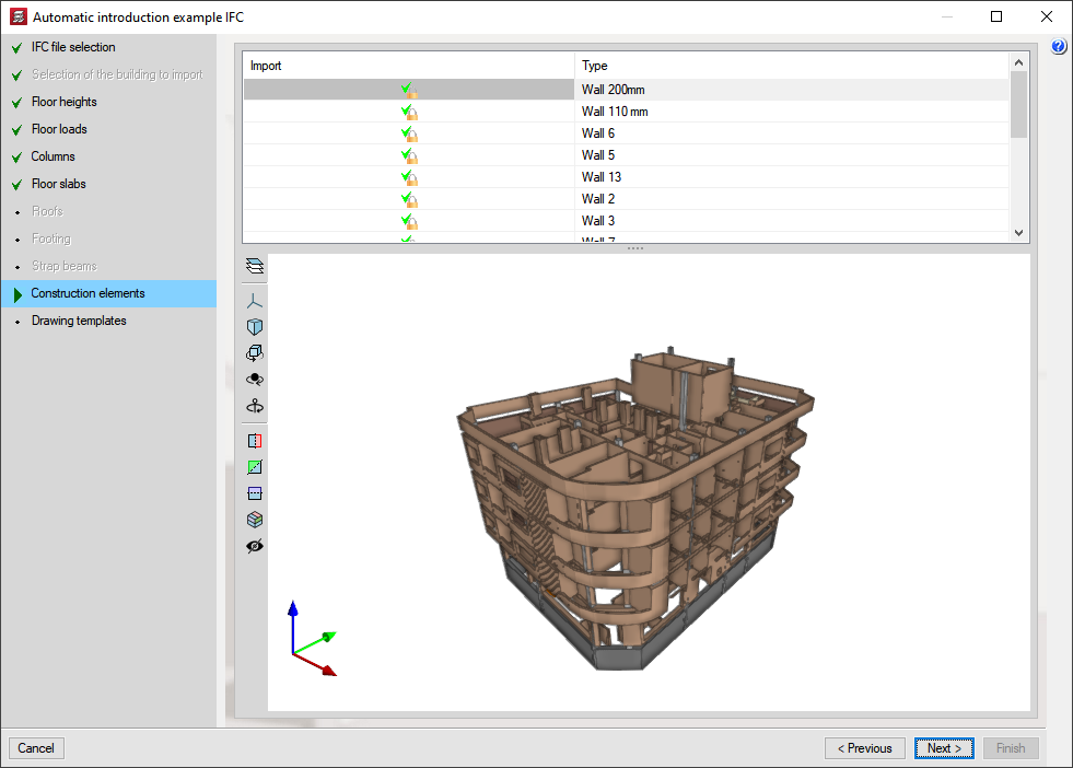
Construction elements
Here, a list of all the wall and partition type elements (IFCWALL and IFCWALLSTANDARCASE) contained in the IFC file is displayed. The user activates the walls and partitions for which their loads are to be obtained to place them automatically as line loads in the job in CYPECAD.
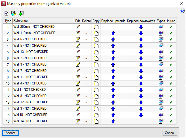
CYPECAD obtains the value of the line loads based on the dimensions of the selected walls and partitions and the surface loads chosen by the user from a dialogue box in which the composition and surface weight of several types of walls are indicated. It is possible to choose a generic type of wall whereby the user assigns the value of the surface weight.
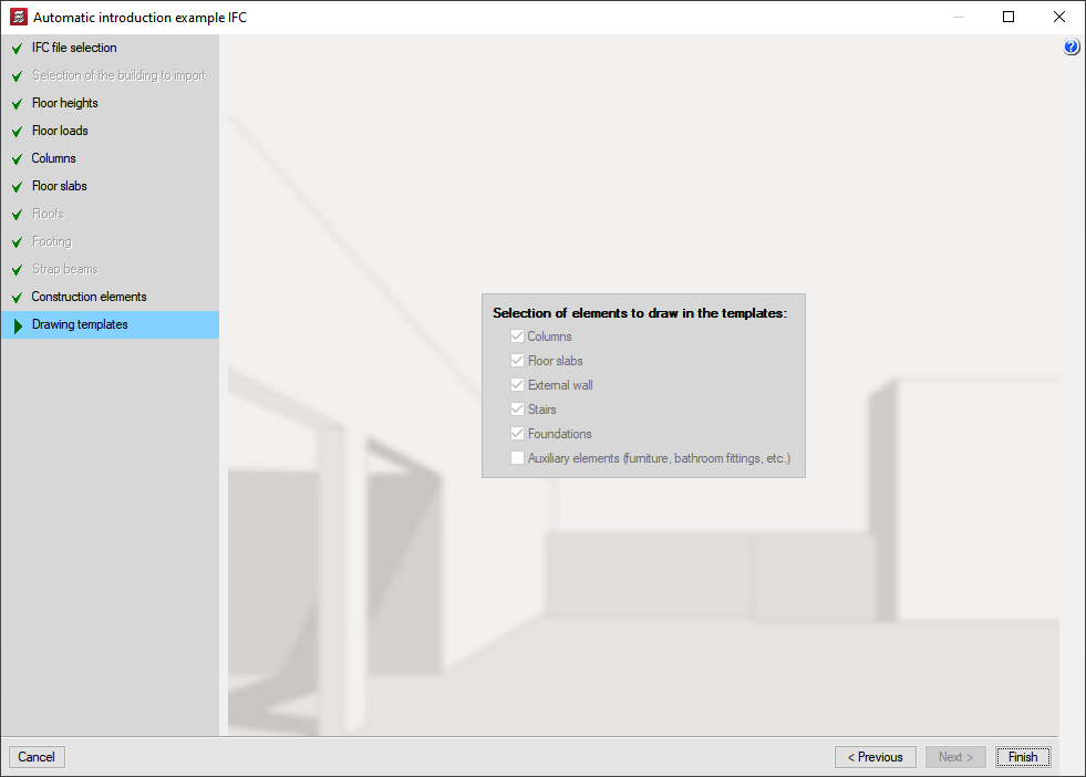
Drawing templates
In this dialogue box, the user can activate the automatic creation of drawing templates to add them to the job in CYPECAD containing the elements selected here: columns, floor slabs, external walls and auxiliary elements. One template is created per floor.
The selection of auxiliary elements is not activated by default. The user may do this, but this will most likely generate a drawing template with excessive information and, therefore, significantly large files.
The IFC file may contain an element that was originally defined as a column, slab or roof element (IFCCOLUMN, IFCSLAB or IFCROOF) in the CAD/BIM program and that is not a structural element and the user does not wish for it to be imported in CYPECAD. A similar case occurs with wall loads; these may not be required as their loads have already been included in the dead load of the floors.
For this reason, the automatic entry IFC assistant allows the user to activate the elements to be imported in the Columns, Floor slabs and Construction elements sections.
In the 3D views of the structure that appear in the Columns, Slabs and Construction element sections, the elements that CYPECAD reads from the IFC file are displayed in different colours. Information on the meaning of these colours can be found in the FAQ section of our web page, specifically in the following question: What do the colours of the different elements that appear in the 3D views of some sections of the assistant for automatically inserting files in IFC format represent?
Interpretation of DXF and DWG files
The Automatic entry module of CYPECAD also interprets DXF and DWG files to automatically generate the structure of the job (floor distribution, general loads, columns, external perimeter and internal openings perimeter beams) thanks to the indications given by the user via the assistant.
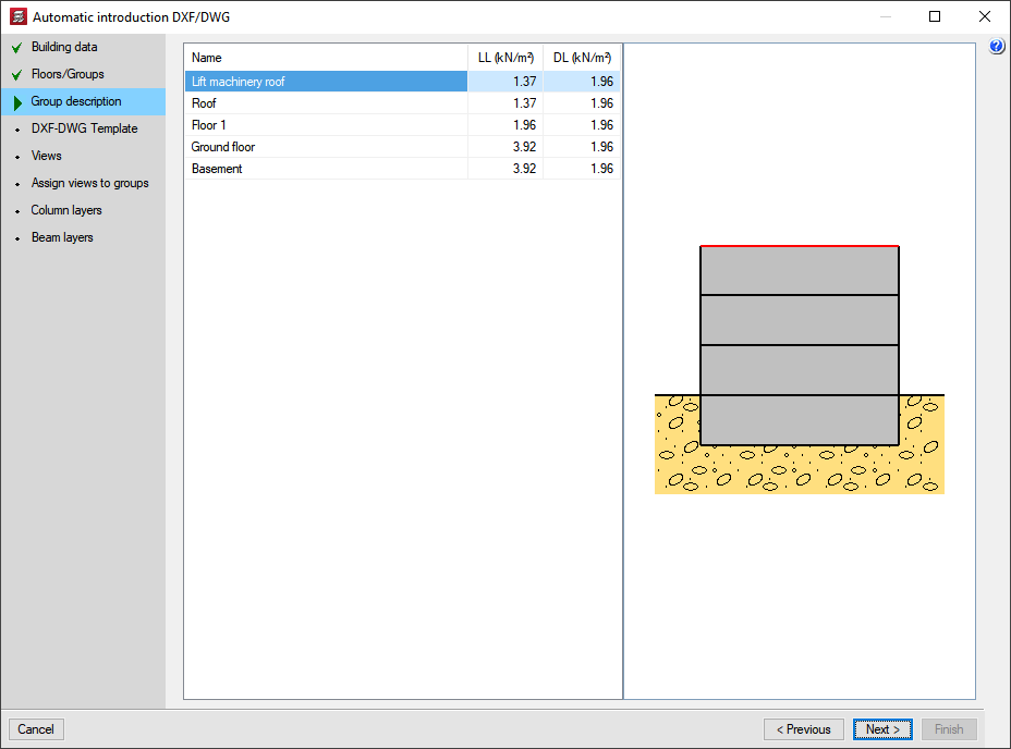
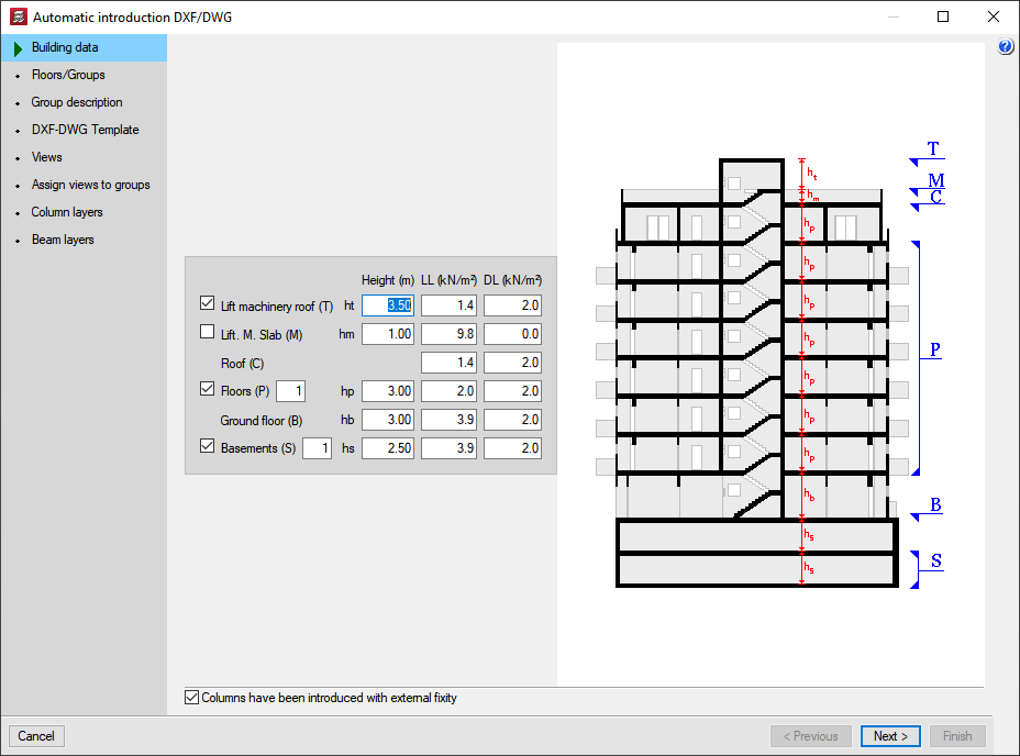
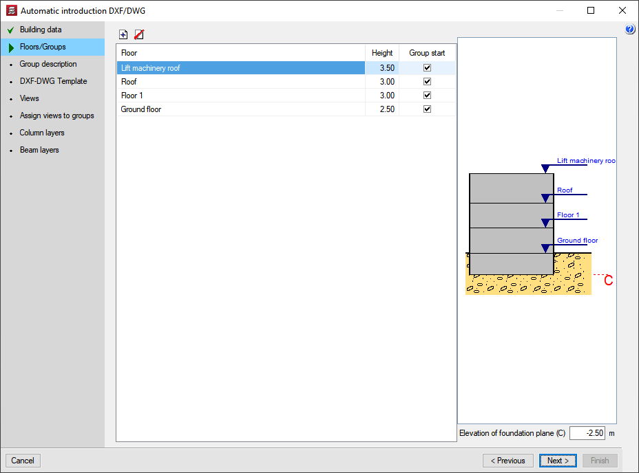
The user defines the floor composition of the structure (basements, ground floor, floors, roof, lift machinery roof, etc). Excluding the ground floor and roof, all the other floors are optional. Their respective heights, live loads and dead loads are also indicated.
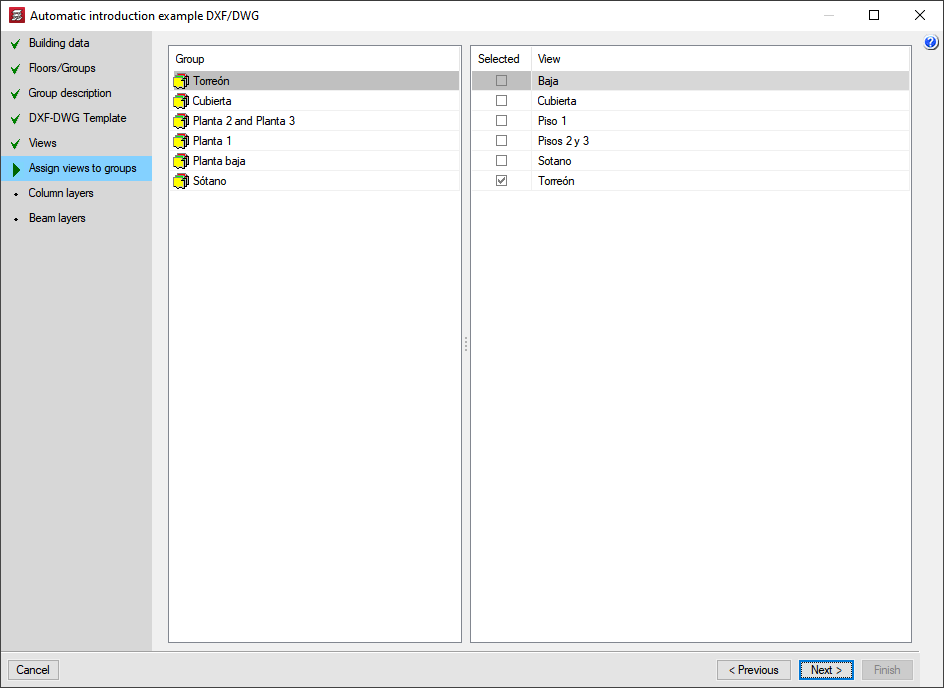
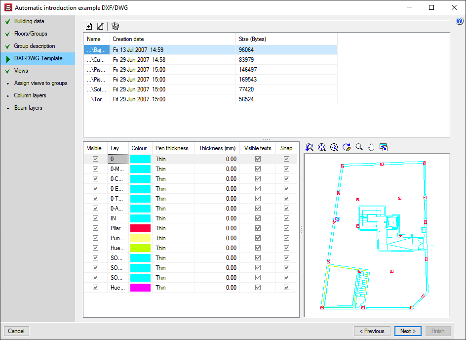
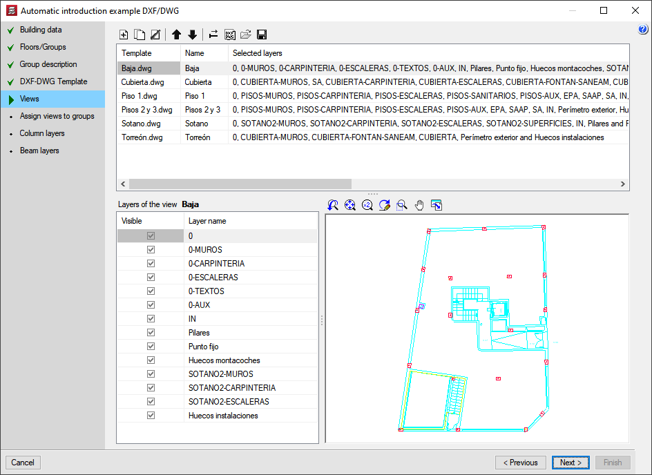
The DXF or DWG files corresponding to the structure are then selected and the layers representing the columns, external outline and opening perimeters are defined.
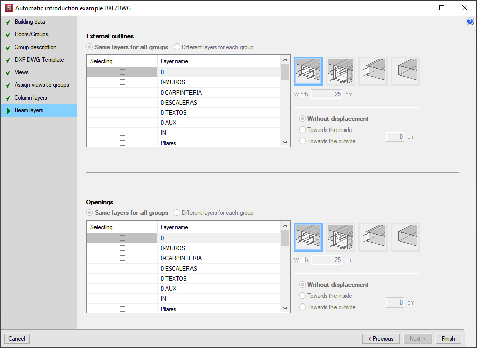
The types of beams defining the external outline of the structure and internal outline of the openings can be selected as well as optionally assigning a displacement to the beam with respect to the original outline. This option may result to be very useful as the outline drawn on the DXF or DWG file may represent the edge position of the façade and not the structural edge.
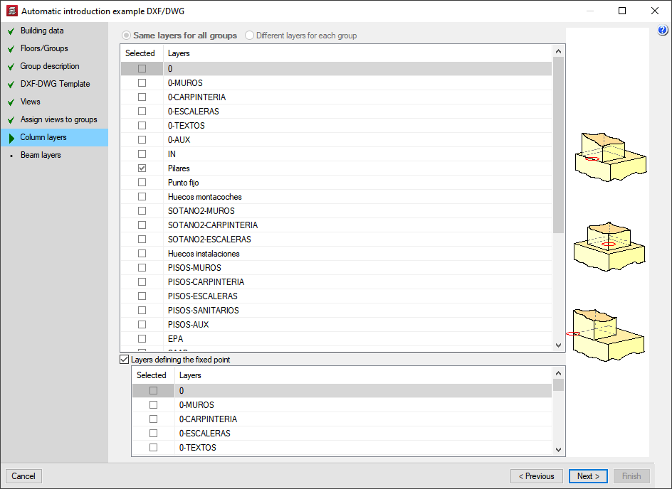
Using all this information, the program automatically generates the geometry of the structure (columns and beams) and even deduces the fixed points of the columns if their dimensions are different on each floor of the DXF or DWG files that have been provided. It is also possible to indicate a layer defining the position of the fixed points of the columns so these are not automatically selected by the program.
Using the geometry of the beams and columns, the user may carry out any manual modifications of the generated structure, enter slabs and complete its definition.
If the user has purchased the Automatic entry module, when entering beams manually, an additional option: Beam entry using Snap mode. This option may be used during the manual entry of beams and assigns any type of beam to a DXF or DWG file polygon or line on any floor. The polygon may be composed of straight or curved lines and may be open or closed. This way it is not necessary to have to enter the polygon geometry beam by beam.
Export to IFC format
CYPECAD also allows for the job to be exported to IFC format. To do so, users are not required to have the Automatic entry module. More information can be found in the Exporting to IFC format section on the CYPECAD page.
Other features
In order to access further features offered by the program, there are several modules that can be found on the "CYPECAD modules" webpage.