Update history​

CYPELEC Core

Adjustment factors for more than three current-carrying conductors in the same conduit

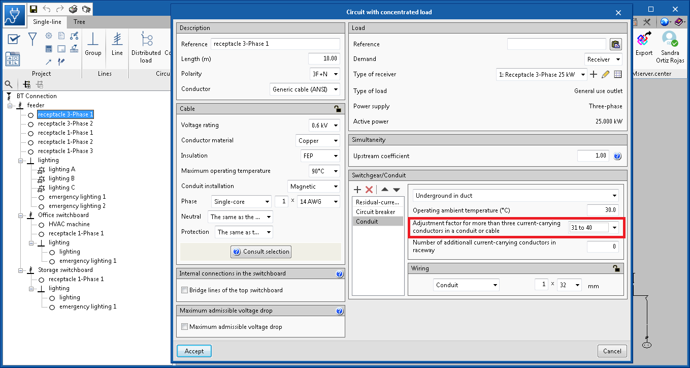
If users are designing an installation that follows the ANSI standard, it is now possible to edit the number of current-carrying conductors in the same conduit, with the aim to adjust the correction factor of the ampacity of the cable in accordance with table 310.1(B)(3)(a) of the NEC code (National Electrical Code).

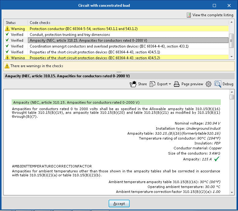
This selection will be reflected in the justification report of the ampacity of the cable.

Names of the phases in a three-phase system

The 2020.a version of CYPELEC Core includes two new ways to identify and differentiate the three phases of a three-phase electrical system. These are: "R Y B" and "R G B".

Export drawings to the BIM project

As of the 2020.a version, users of CYPELEC Core, CYPELEC REBT, CYPELEC NF and CYPELEC RETIE can export drawings to the BIM project to which they are linked on the BIMserver.center platform.

Available in English

The 2019.f version of CYPELEC Core is now available in English. Please recall that CYPELEC Core can be downloaded from the BIMserver.center platform.

64-bit Version

As of the 2019.f version, CYPE programs (those downloaded from our website and those downloaded from the BIMserver.center platform) are compiled for 64-bit systems. The 64-bit compilation of CYPE software implies the use of the superior features of 64-bit processors and operating systems compared to those of 32 bits.

Please bear in mind that you must have a 64-bit operating system to be able to work with any 64-bit software.

In any case and as a temporary measure, the 2019.f version is available in 64 and 32 bits on the download area of our webpage. The programs that can be downloaded from the BIMserver.center platform are only available in 64 bits. If you have a 64-bit operating system, you can work with either the 64-bit and 32-bit version of our software, although we strongly recommend that you install the 64-bit CYPE software version.

You can see which operating system is installed on your computer by clicking on "Control panel > System".

Since 64-bit microprocessors began to be massively introduced into personal computers from 2003 and from the Windows XP version, Microsoft already offers the two versions of its operating systems (32 and 64 bits). We understand that almost all our users will have computers with 64-bit processors (x64) and 64-bit operating systems.

It could occur that a user may wish to work with a computer with a 64-bit processor but with a 32-bit operating system. It would be very strange if the computer had a 32-bit processor (x86 - computers over 15 years old). If any of these is your case, we advise you to talk to your hardware or software provider to update your situation as soon as possible. However, you can download the 32-bit version and work with CYPE programs that can be downloaded from our website until your situation is up-to-date.

Translation into Italian and Portuguese

CYPELEC Core has been translated into Italian and Portuguese. Therefore, it can be downloaded from the BIMserver.center and installed in these languages, as well as in Spanish or Catalan, for which it was already available as of its first version.

Automatic voltage drop design

As of previous versions, CYPELEC Core allowed users to activate the maximum allowable voltage drop check for a specific line using the option indicated in the image.

As of the 2019.b version, this limitation becomes a design criterion, in other words, the program will increase the section to comply with the imposed limit.

Increase in the number of circuits or number of conductors per pole

The group correction factors of all the installation methods corresponding to the UNE 211435 and IEC 60364-5-52 codes have been checked, to increase the number of conductors per pole (number of circuits) from 9 to 20.

It is possible that some tables, for certain installation methods, do not provide a group correction factor for a high number of conductors, in which case the program uses the most unfavourable factor amongst those indicated in the table, and indicates it with a warning message when checking the maximum admissible current or ampacity.

This increase allows users to use, for example, cables of over 2500 A for transformer outputs.

Electric supply using two generators in parallel

As of the 2019.b version, CYPELEC Core, CYPELEC NF and CYPELEC REBT allow for the electrical supply to be provided by two generators connected in parallel, one of which configured as the main supply and the other a complementary supply, to provide for all the installation.

Connection between CYPELEC Networks and CYPELEC Core, CYPELEC NF and CYPELEC REBT

CYPELEC Core, CYPELEC NF and CYPELEC REBT design low voltage installations. In previous versions of CYPELEC Networks, users had to manually introduce the loads that correspond to the low voltage installations (calculated in the aforementioned programs), which are supplied by the medium or high voltage network, and were going to be analysed in CYPELEC Networks.

As of the 2019.b version, and thanks to the Open BIM connection of these programs, CYPELEC Core, CYPELEC NF and CYPELEC REBT can export the demanded or foreseen power (power and power factor) that is required by the installations they design to the BIM model.

This way, when a project is begun in CYPELEC Networks, by connecting to the BIM model to which the demands of the installations that have been designed in CYPELEC Core, CYPELEC NF and CYPELEC REBT have been exported, CYPELEC Networks users will be able to import the IFCs that are generated by the programs and will decide which loads will be part of the high or medium voltage diagram.

To select these loads, CYPELEC Networks has a new tool represented by Carga importada, located in the “Terminal elements” section of the toolbar.

When this tool is selected, the program allows users to select the desired load among those imported from the BIM model to include it in the diagram and continue with the electrical installation. Each time this tool is selected, one of the imported loads can be selected.

If the imported load is single-phase, it will be possible to select to which phase is connected.

In the project, imported loads can be combinedand user can introduce their own loads created directly in CYPELEC Networks.

Expand/contract and find lines in the tree diagram of the installation

In the “Single line” tab, a toolbar has been added in the part above the tree structure of the installation that allows users to expand and contract the diagram, and search lines of the single-line diagram. When a specific line is sought, the line that is found is indicated in the tree structure and highlighted in the diagram.

Enlarged fuses library

Nominal current fuses: 224 A, 355 A and 450 A, have been added. This selection is deactivated by default. It can be activated in “Configuration” > “Elements library” > “Fuses”. This way, the new currents will be available when the fuses are edited.