Update history​

StruBIM Design

Seismic loadcases

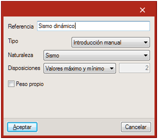
As of the 2017.h version, users can define or import forces in seismic loadcases. Seismic load patterns can include simple seismic load patterns with one or more load arrangements defined by series values, and seismic load patterns defined using envelopes with maximum and minimum values.

The forces of the elements in loadcases associated with seismic load patterns defined by a “Series of values” can be consulted or defined for each arrangement. In combinations in which this type of loadcase intervenes, each of the layouts defined will be combined with the other terms of the combination.

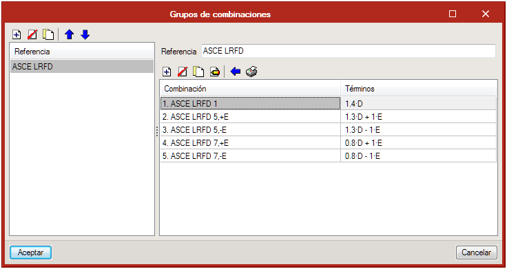
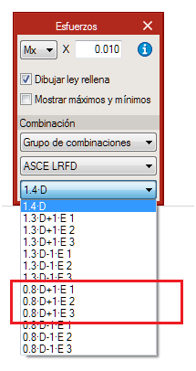
For example, the combination 0.8•D+1•E, where E is a seismic loadcase with 3 load layouts, will generate 3 combinations, one for each layout:

  • Combination 1: 0.8•D+1•E1
  • Combination 2: 0.8•D+1•E2
  • Combination 3: 0.8•D+1•E3

The forces of the elements in loadcases associated with the seismic load patterns defined by “Maximum and minimum values” can be consulted or defined by a group of maximum values and another of minimum values. The design and check of the structural elements are carried out with the combination of each force (maximum or minimum) and the remaining forces (maximums or minimums ).

 NVxVyTMxMy
Min.NminVx,minVy,minTminMx,minMy,min
Max.NmaxVx,maxVy,maxTmaxMy,maxMy,max

For example, the combination 0.8•D+1•E, where E is a seismic loadcase defined by “Maximum and minimum values”, will generate 64 different force combinations where the maximum or the minimum value of each of the 6 forces of the seismic load pattern will intervene:

  • E1 (Nmin; Vx,min; Vy,min; Tmin; Mx,min; My,min)
  • E2 (Nmin; Vx,min; Vy,min; Tmin; Mx,min; My,min)
  • E3 (Nmin; Vx,min; Vy,min; Tmin; Mx,min; My,min)

Ground bearing slabs

As of the 2017.h version, a subgrade modulus can be assigned to slabs defined in floor plans, regardless of whether they are imported or introduced by users.

The analytical model that is generated based on a mat foundation for which a subgrade modulus has been defined, will be assigned that subgrade modulus in the X, Y and Z directions. This however, can be edited for any direction.

In the “Floor plans” tab, users can consult soil pressure in the contour maps for the different loadcases and combinations. The program checks that allowable bearing pressure defined in “General data” is not exceeded and that there are no uplift points for any combination.

Check shear outside the plane in walls

The option to check shear outside the plane in walls is not obligatory; in previous versions, it was.

When users indicate for it to not be checked, the check report of the wall will indicate the acting shear, the shear resistance of the concrete section of the wall, and if necessary, the required reinforcement area.

Import reference lines

Users can now import reference lines which make up a grid during the creation process of the project using a BIM model.

User warnings

Users can configure the program to generate additional warnings to those provided by the code.

In columns, if the “Continuity criteria” option is activated, a warning is generated for each column span when the number or the diameter of longitudinal bars is less than that of the span above.

For columns, walls and beams, users can indicate for a warning to be generated if a certain steel reinforcement area, defined by them, is exceeded. This is an additional warning or check to those required by the code.

Column design options

Two new design options for columns have been implemented:

  • The number of bars must be greater than or equal to that of the floor above.
  • The diameter of the bars must be greater than or equal to that of the floor above.

By activating these options, the number of bars remains the same or is reduced on higher floors, and the diameter of the bars remains the same or is reduced on higher floors.

Punching shear reinforcement design

Design

The program now automatically designs punching shear reinforcement. In previous versions, the critical punching shear perimeter was only generated for columns or column groups that were not in contact with beams. During the design process, the program regenerates and automatically checks the critical punching shear sections. The design process can be executed from the Punching shear menu (affects only the selected floor) or from “Project > Design” (affects the selected plan or all plans).

The design of all the punching shear reinforcement can be carried out using the forces of the global analytical model or those of the analytical model defined for the floor plan.

Design options

The punching shear reinforcement can be designed using shear studs or stirrups. The type of reinforcement can be selected before the design process begins in “General data > Design options > Punching shear”.

Post-tensioned slabs

Introduction

Implemented in the 2017.e version is the design of post-tensioned slabs. This improvement has been created to design the passive reinforcement of post-tensioned slabs, having calculated the forces in the post-tensioning tendons (adherent or non-adherent), and whose properties have been introduced by users.

Users can introduce the path of the tendons, their definition, their stressing loads and their losses (instantaneous and differed). The program generates two post-tensioned load patterns (one with the instantaneous loss and another with the total loss) in which the deviation loads, due to the path of the tendons are introduced. The program also creates three loadcases, two equivalent to the previously mentioned load patterns, and one hyperstatic loadcase with the total loss.

Due to the path of the tendon, forces are produced acting towards the inside of its curvature. The program automatically generates these loads for each tendon. These loads will affect the floor slabs when the local model of that floor plan is analysed. The discretisation of the floor slab during the local analysis is carried out using triangular finite elements which are adjusted to the path of the tendons.

The post-tensioning effect is taken into account when calculating the reinforcement areas required in the slab. When a tendon crosses a critical punching shear perimeter, its effect is taken into account.

Floor slabs containing tendons will be checked and will be designed as post-tensioned slabs in accordance with the ACI 318-14, ACI 318-11 and ACI 318-08 codes.

Generation of loadcases and combinations

In the dialogue box that appears when generating a local model, users can select to automatically generate post-tensioned load patterns. By activating this option, the post-tensioned load patterns, loadcases and combination groups are generated.

  • Load patterns
    PT Transfer with the instantaneous losses and PT Final with the total losses (instantaneous plus differed) in which the deviation loads produced by the path of the tendons will be introduced.
  • Loadcases
    Three loadcases are created, one equivalent to each of the previously mentioned loadcases and a third hyperstatic loadcase with the total loss.
  • Combination groups
    Four combination groups are created: PT Flexural strength (Ultimate)PT Service (Initial)PT Service (Normal) and PT Service (Long term). Each post-tensioned state will be assigned one of these combination groups.

Implemented tools

  • Flexure lines
    The intersections, on plan, of the flexure lines with the paths of the tendons represent the points where the tendon curves to reach its maximum elevation.

    Flexure lines can be introduced between two points and on reference lines.
  • Tendon introduction
    There are several tendon introduction options: Introduction of a single tendon, introduction of concentrated tendons and introduction of distributed tendons. The difference between these options lies in the way the number of tendons that have to be introduced are defined.
    • One tendon
      One tendon is introduced between two points.

    • Concentrated tendons
      El usuario indica la separación entre los tendones y el número de ellos o el ancho de banda.

    • Distributed tendons
      Users indicate the spacing between tendons. Once the dialogue box has been accepted, the path of the tendons is defined graphically, and the strip width along which they are to be placed.
    With each of these options, users can define:
    • Section
      Number of strands, their cross-sectional area and their type (adherent or non-adherent).
    • Tendon material
    • Load
      Transfer load pattern, final load pattern, stressing load and end at which the stress is being applied.
    • Stressing loss
      Three options appear to define the stressing loss:
      • Stressing force percentage
      • Specified value
      • Detailed analysis, based on the friction coefficient due to the curvature, friction coefficient due to accidental deviation, spacer penetration, loss due to elastic shortening of the concrete, loss due to creep of the concrete, loss due to concrete shrinkage and loss due to steel relaxation.


  • Tendon schedule

    The different properties of the tendons can be edited in the tendon schedule (previously defined during the introduction), as well as the elevations.


    By editing the diagram, users can modify the path of the tendons on the elevation view of the slab. There are several types of elevations that can be assigned to each tendon span:

    • Linear
    • Parabola
    • Reverse parabola
    • Harped one point parabola
    • Harped two point parabola
    • Partial parabola - left
    • Partial parabola - right
    • Partial rev. parabola - left
    • Partial rev. parabola - right


  • Representation tools
    The tendon groups (concentrated or distributed) can be represented as being grouped or ungrouped. There are label management tools, in case users choose to represent the tendons as grouped. These tools allow user to add, edit, move, and delete labels as well as select the visible tendon of the group.


  • View options
    From the Draw menu, users can access the View options, where several options have been added to view prestressed related elements.

Results output

Different reports are generated indicating the properties, elevation geometry and checks of the tendons.

The program also generates floor plans with the tendon distribution and dimensions selected by users in the drawing configuration. Users can also include the Properties table, the elevation properties table and elevation curves table.

Local analytical models of floor drawings

Introduction

Local analytical models of the floor plans can now be generated, edited and analysed, with the 2017.e version. The local models allow for a floor of the global model to be analysed independently from the rest of the floors, improving the flexibility during the structural analysis. The design of the structural elements of the floors can be carried out with the forces of one model or another.

Generation

To generate a local model, select the “Generate” icon. There are several possible situations that affect the generation process:

  • Generation of local analytical models in projects without an associated BIM model
    This type of project has been created without the help of an IFC or XML file from the start, or it has been created using an IFC or XML file but the link with the BIM model has not been kept. In these cases, when users click on “Generate” a panel appears where the type of external fixity to be assigned to columns can be selected, as well as the discretisation size for slabs and walls.

    The floor plans of this type of projects generate an analytical model composed of floor slabs, beams, columns and walls defined on plan. Neither loads, loadcases, nor combinations are generated. Columns and beams generate bars, and slabs and walls generate finite element shells.
  • Generation of local analytical models in projects with an associated BIM model
    This type of project has been created based on an XML or IFC file. Regardless of whether a global analytical model has been defined or not, the floor plans of this type of project generate an analytical model based on the BIM model of the floor.

    If a global analytical model exists (imported using an XML file or from a results file exported from StruBIM Analysis), the model that is generated will contain a group of loadcases and load patterns equivalent to those of the global model and one or more combination groups of these loadcases. Loads, displacements and fixities are generated in accordance with the type of model that is selected by users amongst the following:
    • Only with floor loads
      In this case, a model is generated with the beams and slabs defined on the floor plan and the spans of columns and walls that reach that floor. The wall spans that stat at that floor generate a beam with the same section as the wall. Regarding loads, the loads defined in the corresponding floor of the global analytical model are generated.
      Floor loads and elements starting on the floor
      In this case, a model is generated with the beams and slabs defined on the floor and the column and wall spans that reach that floor. The wall spans that start on that floor generate a beam with the same section as the wall. Regarding the loads, the program generates the loads defined in the corresponding floor of the global analytical model and the loads reaching the floor from elements on higher floors which bear their loads on that floor.
      Floor loads, elements starting on the floor and displacements of the supports
      In this case a model is generated with the beams and slabs defined on plan. The spans of the columns below generate a support, which is fixed or pinned depending on what users select. Regarding loads, the program generates the loads defined in the floor in the global analytical model, the loads reaching the floor from elements on higher floors which bear on that floor, and the displacements of the columns of the global model by loadcase such as displacements prescribed at the supports, as well as the corresponding loadcases and load patterns.

    If the global analytical model is not available, the model that is generated will be that of the first case, but without any information of the global model. In all cases, non-deformable zones at the top of columns will be generated as will the necessary trims at column and beam ends due to the dimensions of the nodes.

Editing

To edit a local model, the “Edit” button must be selected. The editing process of the model is carried out using an interface similar to that of StruBIM Analysis, where users can edit the discretisation size of the shells, fixity coefficients, stiffness factors, mechanical properties of the bars, acting loads...

Updating

The local analytical model can be updated in two ways:

  • Using the “Update” option in the floor plans tab
    In this case, this option transfers the thickness of the slabs, beam sections and materials from both elements to the analytical model. For elements whose properties are not the same, StruBIM Design displays a warning sign.
  • When the global BIM model is updated
    In this case, the local analytical models of the floor plans that have been defined, are updated. If only the forces of the global model are updated, StruBIM Design will update the loadscases, load patterns, loads and displacements of the local analytical model.

Management of the local model for the comparison and design of elements

Once the local analytical model has been generated for a floor plan, the forces of the model will be used, by default, to design and check all the elements contained in the plan. Using the “Edit” option from the floor plans list, users can indicate they wish to use the global analytical model again for all the elements of the plan.

Floor slabs are always designed and checked using the local analytical model defined for the floor plan. When there are floor plans with a local analytical model, StruBIM Design allows users to indicate, for beams and punching shear zones, whether the local or global analytical model is to be used.

Results consultation

The results from the analysis of the local model can be viewed in the Deformed shaped and contour maps window, and from the Slab forces and Beam forces windows.

  • It is possible to alternate between the view of the forces of the global model and the local model. As well as the forces, the displacements and stresses can be consulted.

User manual, Calculations manual and videos

The user and calculations manuals of the free-access online version of StruBIM Design, as well as a series of demonstration videos of StruBIM have been edited. This information can be found in the following links:

New tools in StruBIM Design

Several tools have been added in the 2017.b version for improved use of the following program tools:

Column schedule

  • Show/hide columns
  • Select columns on floor plan view
  • Options that can be assigned:
    • Presence on plan
    • Section
    • Reinforcement
    • Design properties

Wall schedule

  • Show/hide walls
  • Select walls on floor plan view
  • Options that can be assigned:
    • Presence on plan
    • Section
    • Reinforcement strips
    • Reinforcement
    • Design properties

Floor plans

  • Copy floors
    Allows users to copy floor slab reinforcement, punching shear critical sections and reinforcement, frame reinforcement and sections from one floor to others.

Concrete beam table

  • Options to assign:
    • Section
    • Reinforcement
    • Design properties
  • Reinforcement diagram depending on the type of span
  • Select beams on floor plan view
  • Improved view of required reinforcement diagrams

Steel beam table

  • Options to assign:
    • Section
    • Design properties
  • Select beams on floor plan view

Steel beams

The 2017.a version includes the design and check of steel beams in accordance with the requirements of the ANSI/AISC 360-10 code.

The types that have been implemented are:

  • I-section
  • Circular hollow section
  • Rectangular hollow section
  • Rectangular reinforced box