Update history​

StruBIM Design

Punching shear check

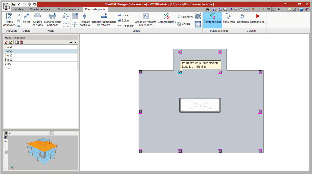
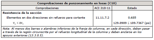
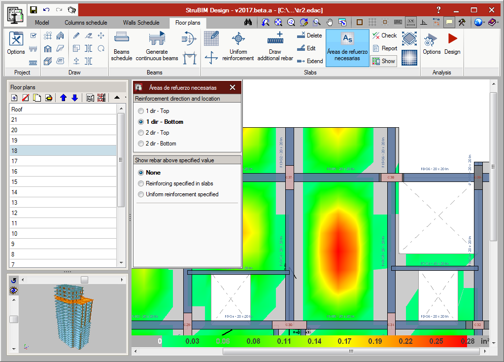
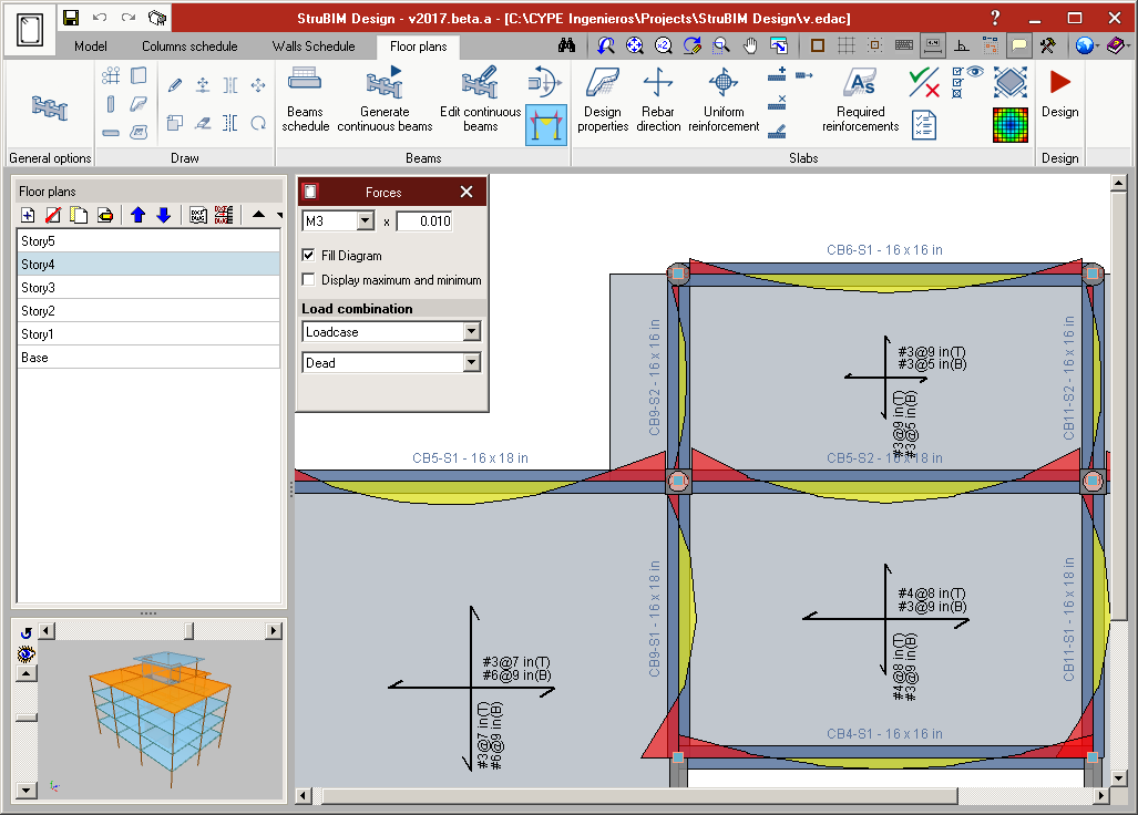
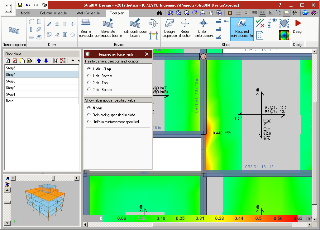
As of the 2017.a version, StruBIM Design carries out a punching shear check on floor slabs supported by columns. The program automatically generates the critical section for each column that transmits forces to the floor slab and allows for it to be edited. StruBIM Design verifies, for the critical perimeter, if the resistance against tangential stress is exceeded in floor slabs without shear reinforcement, which resist bending in both directions. Additionally, users can now introduce shear reinforcement in floor slabs and check critical sections with reinforcement.

The program allows users to introduce shear reinforcement as stirrups or shear studs and verifies the resistance at the perimeters at either side of the reinforcement. Furthermore, StruBIM Design checks the geometric layout and reinforcement in accordance with the design code.

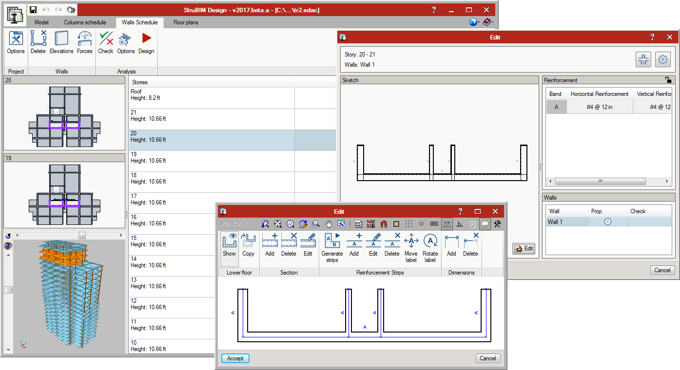
The layout of the column can be modified (centre, edge or corner), as can the effective depth of the floor slab, the maximum and minimum width of the support, and the critical perimeter of the support and reinforcement (taking into account openings and edges, indicating the effective segments against punching shear). It is also possible to modify the reinforcement data of stirrups and shear studs.

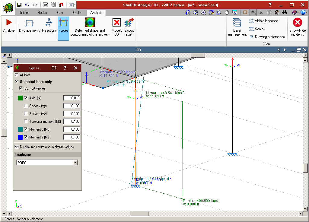
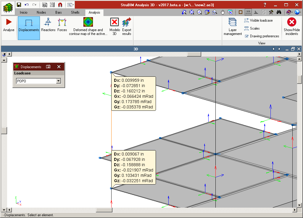
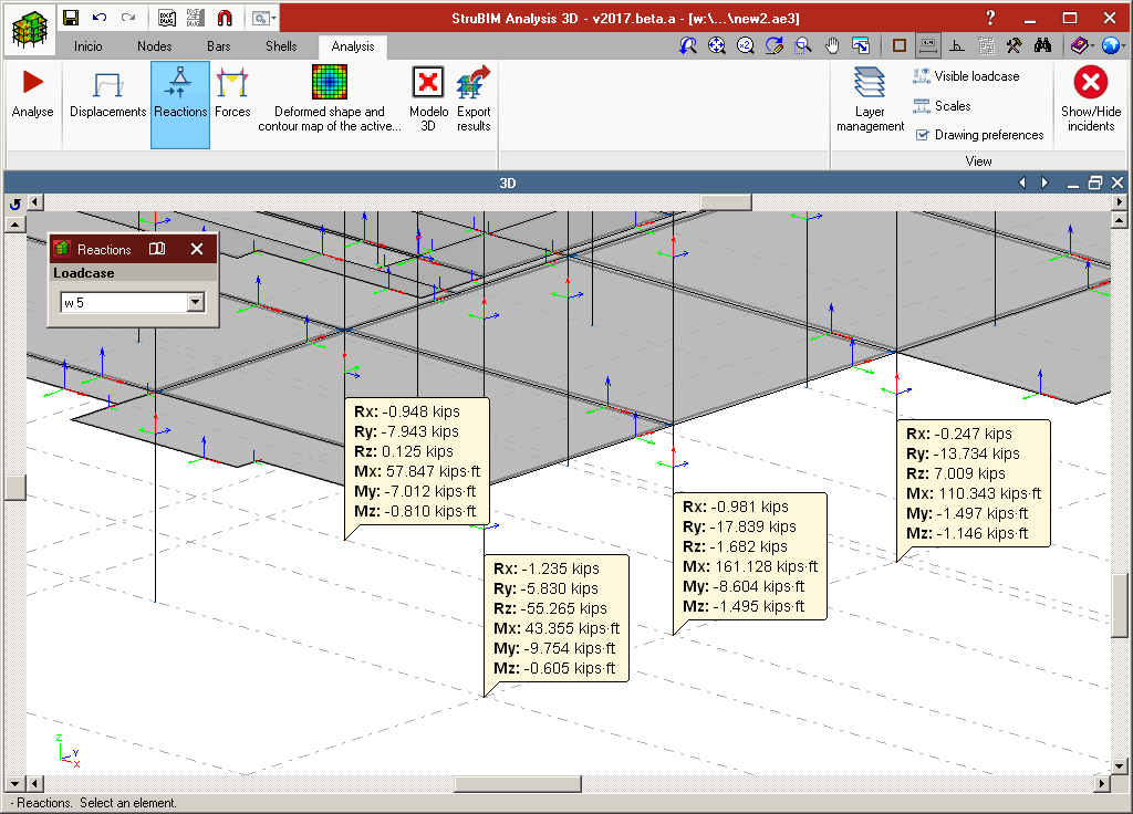
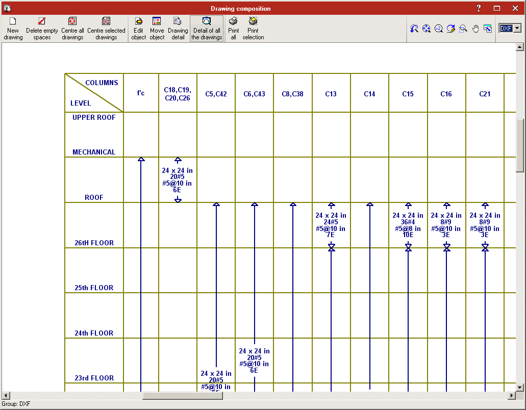
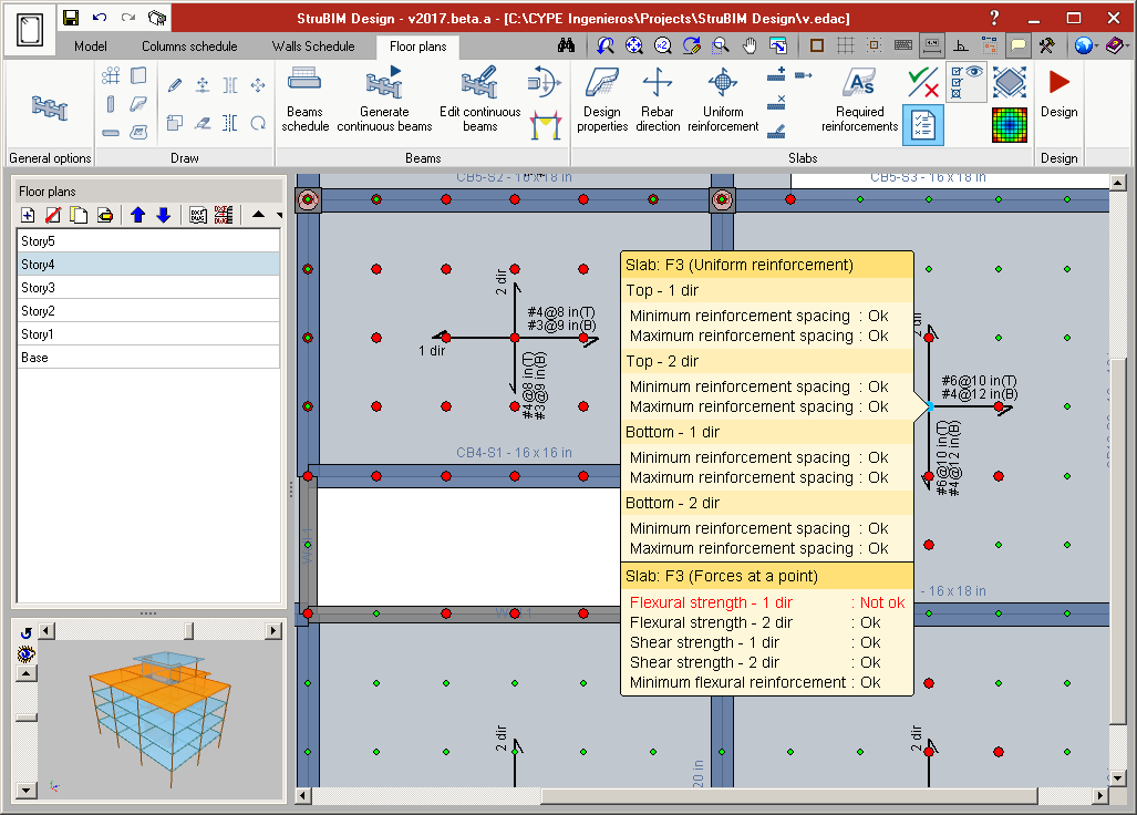
The forces at the top and bottom of each support can be consulted. The difference between these forces corresponds to the punching shear forces transmitted to the floor slab at that floor.

Punching shear of columns close to each other, with their internal and external perimeters together, can be checked and their perimeters edited.

Confinement reinforcement in concrete walls

As of the 2017.a version, users can select between two types of reinforcement for wall spans: “Reinforcement by faces” (this is the type in previous versions) and “Confinement reinforcement” (new type). This new type allows for typical reinforcement to be defined at wall ends.

A shear wall can be composed of several spans with the same or different thickness. Each span of the wall can be assigned different reinforcement strips, for their composition or type.

  • Reinforcement by faces
    A bar diameter is defined as well as the horizontal and vertical reinforcement spacing, which will be the same for either side of the wall.
  • Confinement reinforcement
    The number of longitudinal bars per side of the wall and their diameter is defined, as well as the transverse reinforcement composed of closed stirrups and intermediate cross-ties (column-type).

The program designs and checks the reinforcement depending on the selected type.

Column design properties

As well as the existing design properties of previous versions, the 2017.a version implements options to edit the following properties:

  • Sway moment magnifier (s in ACI 318)
    This factor amplifies moments for wind and seismic nature loadcases in concrete columns.
  • Reduction factor for reducible live loads
    Forces belonging to loadcases with “Reducible live load” nature are multiplied by this coefficient.
  • Unbraced length for buckling due to bending
  • Unbraced length for buckling due to torsion
  • Effective length factor
  • Non-sway moment magnifier (B1, ANSI/AISC 360-10)
  • Non-sway moment magnifier (B2, ANSI/AISC 360-10)
    This factor amplifies moments for wind and seismic nature loadcases in steel columns.

Concrete and steel composite columns

The 2017.a version of StruBIM Design includes the definition and check of concrete and steel composite columns. These are checked in accordance with the ANSI/AISC 360-10 code.

The types of composite columns the 2017.a version of StruBIM Design can check are:

  • Rectangular tube filled with concrete
  • Welded rolled-steel plates rectangular box, filled with concrete
  • Circular tube filled with concrete
  • Rectangular concrete section with encased steel section
    Rectangular concrete section with longitudinal and transverse reinforcement and encased I-section.
  • Circular concrete section with encased steel section
    Circular concrete section with longitudinal and transverse reinforcement and encased I-section. Stirrups or spirals can be used as transverse reinforcement.

Preferential methods for force integrations in 2D elements

To design and check floor slabs and walls, StruBIM Design processes the results from their analysis based on the finite element method. This analysis provides solutions at specific points of the 2D structure, depending on the established discretisation. Based on these solutions, the design values required for the design and reinforcement are obtained by generating integration strips in the two-dimensional element and the calculation of the resultant in the corresponding design section.

As of the 2017.a version, StruBIM Design offers users the possibility to calculate this resultant by applying the “Internal forces integration method” or “Nodal forces integration method”.

Evaluation of the integration methods

The first premise is to have the internal and/or nodal forces in the 2D elements considered, to be able to apply one method or another. Depending on the origin of the analytical model which is being worked on (xml, sbar, etc.), the available design data may vary. Obviously, when only one of the types of data is available, only the corresponding method can be applied. If both the internal forces and nodal forces are available, it is the user’s choice which method is most adequate. The following observations on the methods can be used to guide users as to which method they should apply:

  • Integration of nodal forces
    The nodal forces integration method provides very good results when the width of the integration strip to calculate the resultant, is the entire width of the 2D element, regardless of the discretisation size used, as occurs when treating walls in StruBIM Design. When the width is smaller, and this method is being applied, it is recommended a more reined discretisation of the two-dimensional element be used.
  • Integration of internal forces
    The internal forces integration method provides very good results when the integration strip width is small, as occurs when calculating the required slab reinforcement in StruBIM Design.

StruBIM Analysis 3D and StruBIM Design are no longer BETA versions

As of the 2017.a version, StruBIM Analysis 3D and StruBIM Design are no longer BETA versions and are completely operational.

Project data and structural element reports

Project data and structural element reports have been implemented in the 2016.k version of StruBIM Design. The report index is as follows:

  • JOB DATA
    • General data of the project
    • Codes considered
    • Actions considered and combinations
      • Load patterns
      • Loadcases
      • Combination groups
      • Limit states
    • Materials used
      • Concrete
      • Reinforcement steel
    • Covers
    • General design properties
  • COLUMNS
    • Reinforcement
    • Forces by loadcase
    • Design properties (Concrete)
    • Checks
  • SLABS
    • Reinforcement
    • Required and provide reinforcement
    • Checks
  • BEAMS
    • Reinforcement
    • Forces by loadcase
    • Required steel areas
    • Checks

Punching shear check

The 2016.k version of StruBIM Design includes a punching shear check for slabs in accordance with ACI 318-08, ACI 318-11 and ACI 318-14. The program automatically generates the critical section for each column that transmits forces to the slab. The program verifies, for the critical perimeter, if the tangential stress resistance is exceeded in slabs without shear reinforcement and exposed to bending in both directions.

Open BIM workflow in StruBIM programs

As of the 2016.k version the view of the BIM model and management of BIM links are incorporated in the program.

The view of the BIM model incorporates the representation of the linked IFC model or models in the view of the bar analysis model.

This view window is opened from the Window menu > Open new > BIM model.

The BIM model can be represented as transparent or solid, as well as having the option to view the analysis model.

In the BIM model window, all the IFC models in the linked models list are displayed. Users can link the IFC files present in the directory containing the IFC files of the physical model with which the analysis model is imported (BIM project directory).

Los cambios en los ficheros IFC del directorio del proyecto BIM se reflejan en el botón de Actualizar, mostrando la advertencia para que actualicemos el modelo.

New StruBIM Suite programs

IFC BUILDER

Creation and maintenance of building IFC models. This application is integrated in the OPEN BIM workflow via the IFC4 standard.

Features:

  • Graphic user interface (GUI) to introduce columns and flat slabs
  • Import of DXF/DWG/JPG/BMP files
  • Open BIM edges generation
  • Open BIM (IFC4) modelling

StruBIM Analysis 3D

StruBIM Analysis 3D is a tool created to generate, edit and design an analysis model that has been developed based on a structural model.

The analysis of the acting loads is carried out using a 3D spatial analysis applying stiffness matrix methods.

The structural model can be imported using an IFC format file, generated using CYPE’s IFC Builder, other BIM modelling programs or an XML format file.

The analysis model is generated based on the imported structural model, and the structure is discretised into bar-type elements, nodes and shells composed of finite elements (FEM). Users can adjust the model by defining or editing:

  • Loadcases
  • Values of loads acting on elements.
  • Wind loads that are generated automatically in accordance with ASCE 7-10
  • Diaphragms
  • Boundary conditions
  • Section and material properties
  • Shell discretisation sizes


Once the analysis has been completed, users can consult:

  • Displacements and reactions
  • Force and displacement diagrams
  • Contour maps for forces and displacements

The analysis model and its results are exported to StruBIM Design.


StruBIM Design

StruBIM Design is a tool which designs, checks and edits reinforced concrete and steel structural elements, based on a structural model and a calculated analysis model.

The structural model can be imported using an IFC format file that has been generated using CYPE’s IFC Builder, other BIM modelling programs or an XML format file. The calculated analysis model is imported from StruBIM Analysis 3D or from the XML file if it contains the necessary information.

StruBIM Design designs and checks structural elements (columns, beams, floor slabs and walls) and provides the technical drawings in accordance with the requirements of the project (Record Engineer).

The reinforcement of the following reinforced concrete elements is designed and checked in accordance with the requirements of ACI 318-14, ACI 318-11 and ACI 318-08:

  • Rectangular or circular-section columns
  • Rectangular-section beams
  • Flat slabs
  • Walls

Steel elements are designed and checked in accordance with ANSI/AISC 360-10.

Design results for reinforced concrete elements (sections and reinforcement) and steel elements (sections) can be edited, and then checked.

Design results can be directly transferred to technical drawings of the various elements: columns, beams, slabs and walls, in accordance with representation requirements and project contents (Record Engineer):

  • Column schedule
  • Beam schedule
  • Slab reinforcement drawings
  • Wall schedule

Versions

Three program versions of StruBIM Analysis 3D and StruBIM Design are available:

  • StruBIM Free
  • StruBIM Pro
  • StruBIM Expert