Introduction
StruBIM Cantilever Walls is a program created to design and check reinforced concrete cantilever walls for retaining soil. It automatically carries out the pre-design of the geometry, the analysis of the stem reinforcement and the geometrical and reinforcement design of the wall footing.
Workflow supported by the program
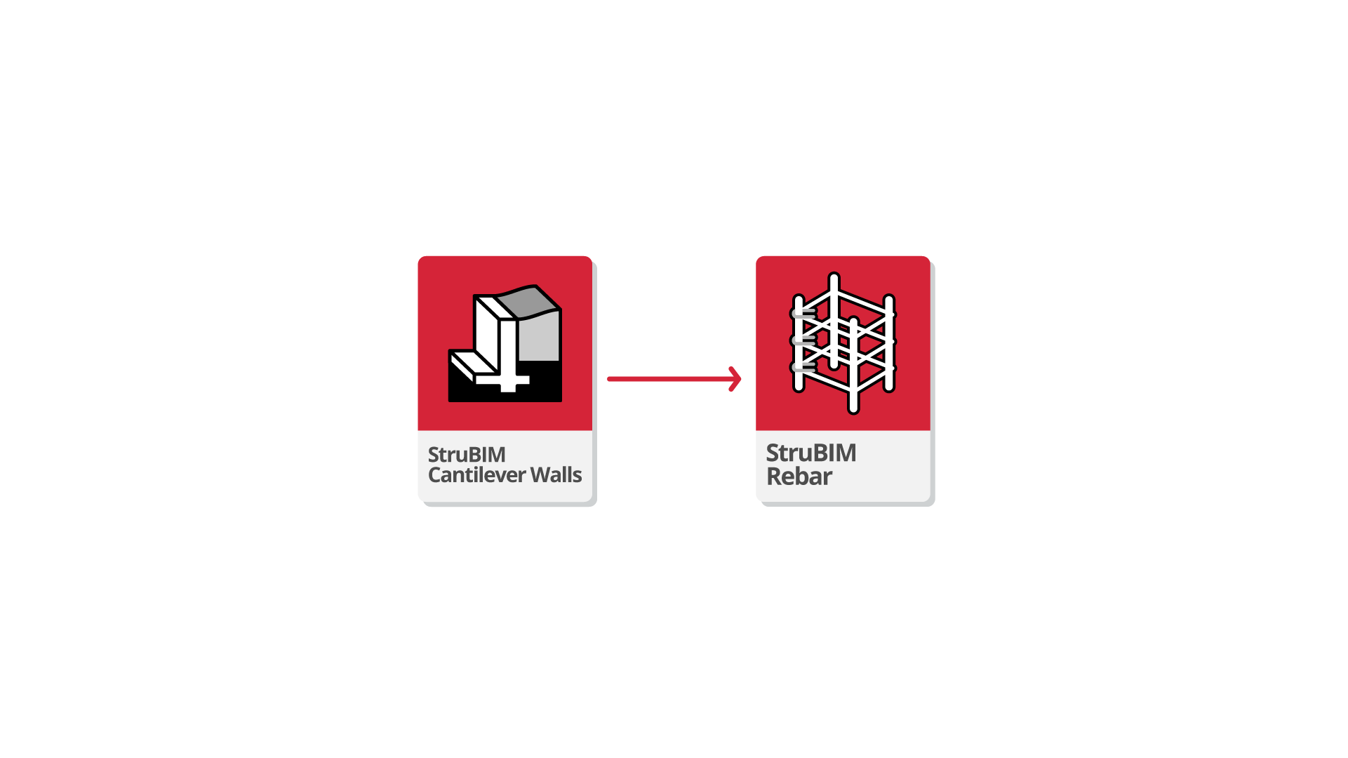
The option to connect StruBIM Cantilever Walls to the BIMserver.center platform further expands the working possibilities offered by the program.
As well as using the tool on its own to obtain the results it provides by itself, users can also export the modelling results to the BIMserver.center platform to integrate them into the BIM project along with the other information layers that may exist.
In this regard, a workflow can be established whereby results generated in StruBIM Cantilever Walls are imported into StruBIM Rebar. StruBIM Rebar can be used for the detailing of designed retaining wall reinforcement and, if desired, can also be exported in IFC and BVBS format.
Work environment
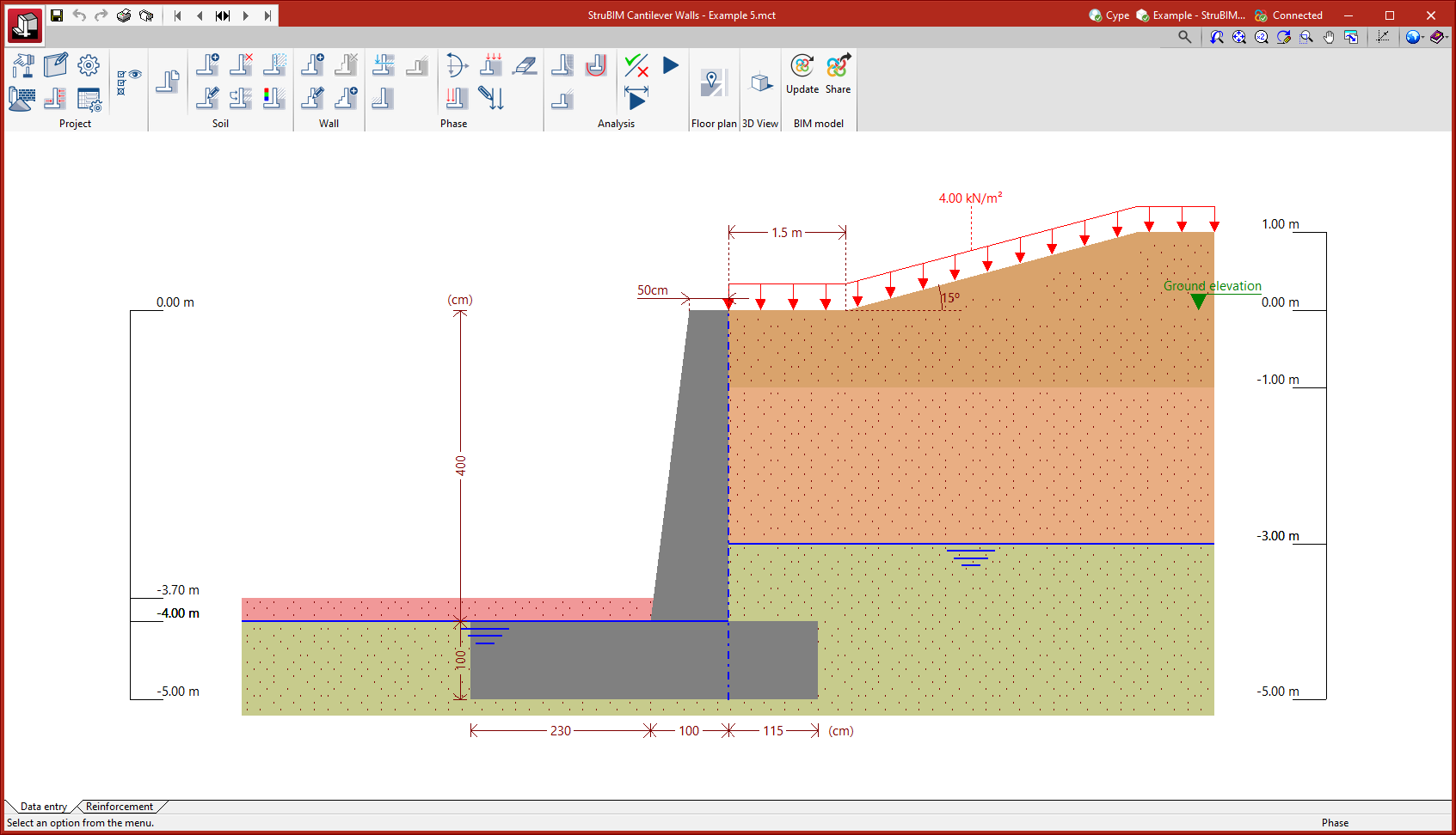
The StruBIM Cantilever Walls work environment is similar to other CYPE programs.
At the top left of the screen, there are two separate tabs: "Data entry" and "Reinforcement".
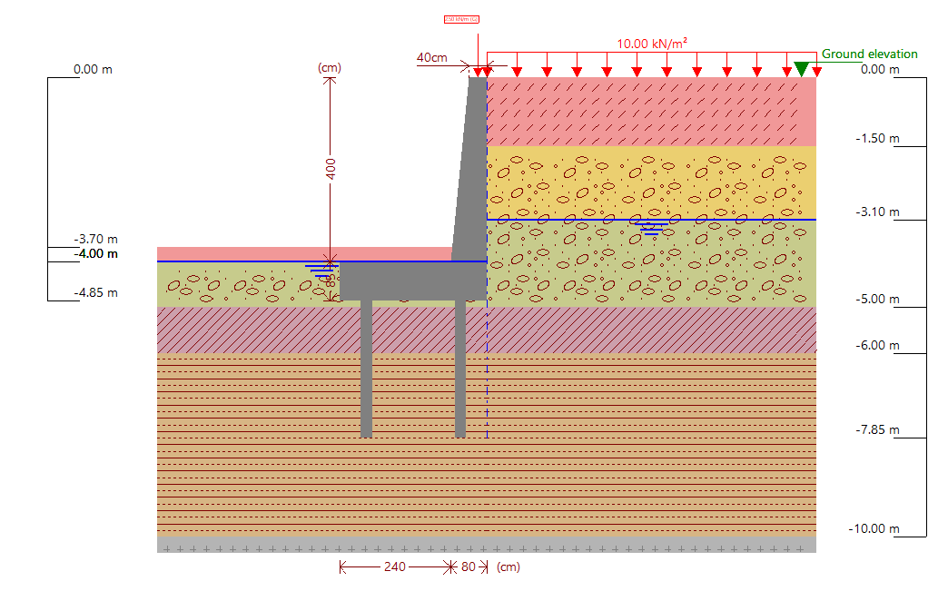
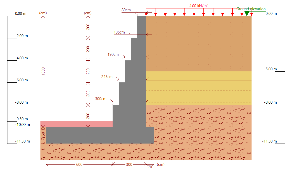
The work area is located in the central part of the screen and displays the characteristics of the project, such as the soil layer, water table, rock soil layer and all types of loads in the backfill and infill, as well as the geometry of the cantilever wall.
The main toolbar contains different features depending on the "Data entry" or "Reinforcement" tab. Users can configure the data and characteristics of the job, soil or wall, as well as enter loads and analyse or design the wall.
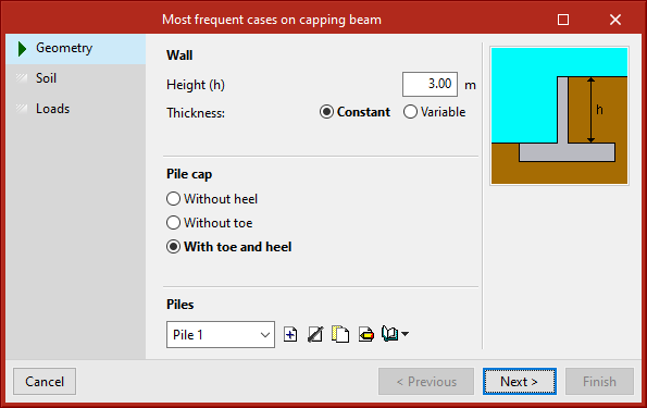
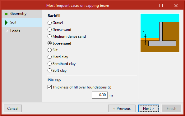
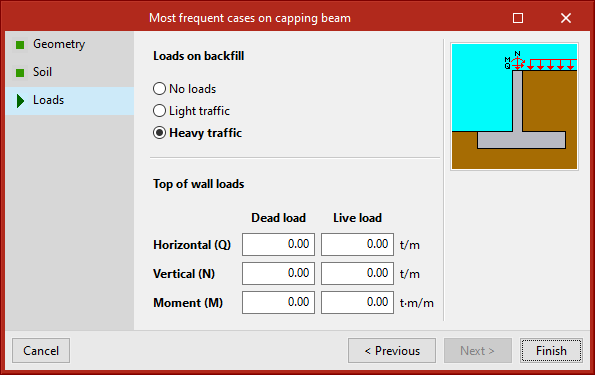
Assistant
When starting a new job, the program offers users the possibility to use an assistant to automatically generate the wall geometry, soil and load data by entering a small number of parameters sequentially.
- Most frequent cases on strip footing
- Most frequent cases on capping beam
Defining the project characteristics
In the "Data entry" tab, in the "Project" group of the main toolbar, the following project data can be defined:

The options available are:
- Type:
The type of foundation can be chosen and can be either fixed, strip footing or capping beam. - General data:
Allows users to choose the geometry parameters for the analysis of the project, such as the height or the alignment of the wall. - Options:
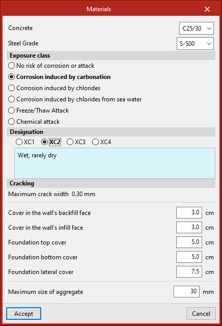
Allows users to select the options to be applied in the analysis, such as safety coefficients. - Materials:
Allows users to select the concrete and steel, as well as other parameters for analysing the project. - Loads:
Allows users to select the types of pressure produced on each face as well as the activation of the seismic acceleration. - Reinforcement tables:
Allows users to create, modify or use the reinforcement tables included in the program. - Show:
Allows users to select the dimensions and information of the soil layers to be displayed in the working area.
Soil
In the "Data entry" tab, in the "Soil" group of the main toolbar, the soil characteristics can be defined:

The options available are:
- General data:
Contains soil data (characteristics, the presence of rock and water table, etc.) of the fill, both in the infill and in the backfill. - New soil layer
Allows users to stratify the soil by entering the depth and characteristics. - Edit soil layer/fill:
Modifies the characteristics of any type of soil or any type of fill. - Delete soil layer:
Allows users to erase one or more soil layers. - Copy soil layer:
Allows users to copy a soil layer along with its characteristics. - Edit soil layer/fill hatching:
Modifies the drawing hatching of any type of soil or fill. - Edit soil layer/fill colour:
Modifies the drawing colour of any type of soil or fill.
Wall
In the "Data entry" tab, in the "Wall" group of the main toolbar, the characteristics of the wall can be defined:

The options available are:
- New span:
Subdivide the wall into sections, indicating the height of each span and its thickness. The reinforcement is divided in each span. - Edit span/foundation:
Allows users to modify the characteristics of the wall or foundation. - Delete span:
Deletes the selected span. - Generate spans:
Can be used to generate steps or to indicate the vertical reinforcement spans. This is recommended for very high walls or walls of constant thickness.
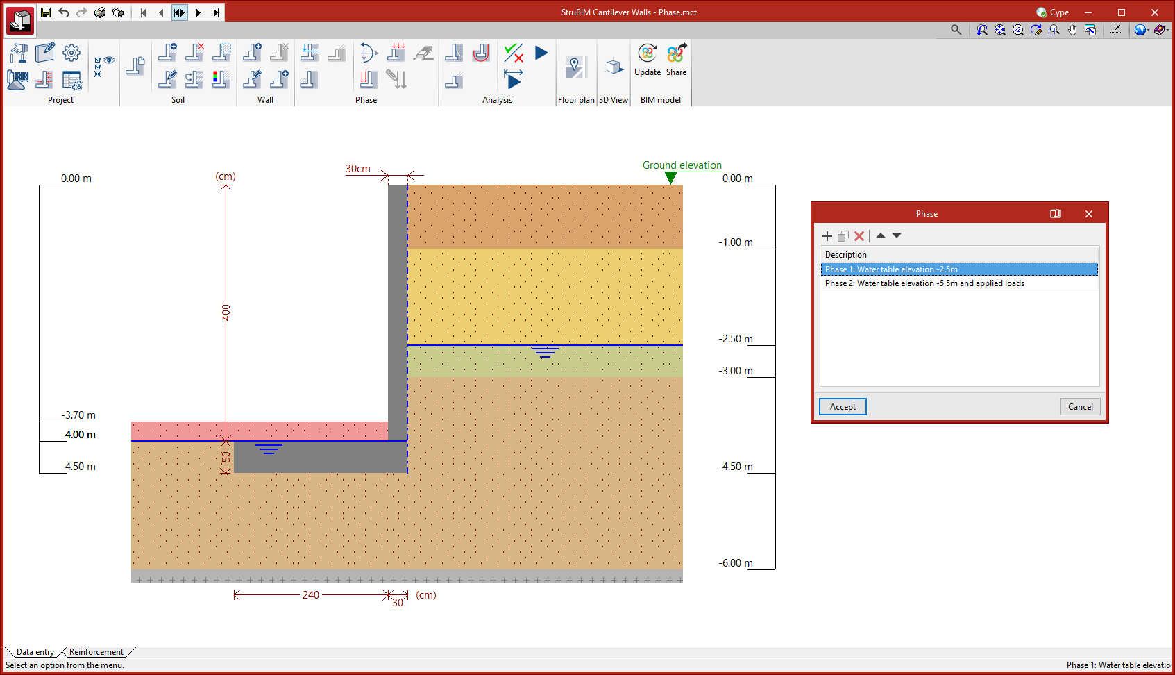
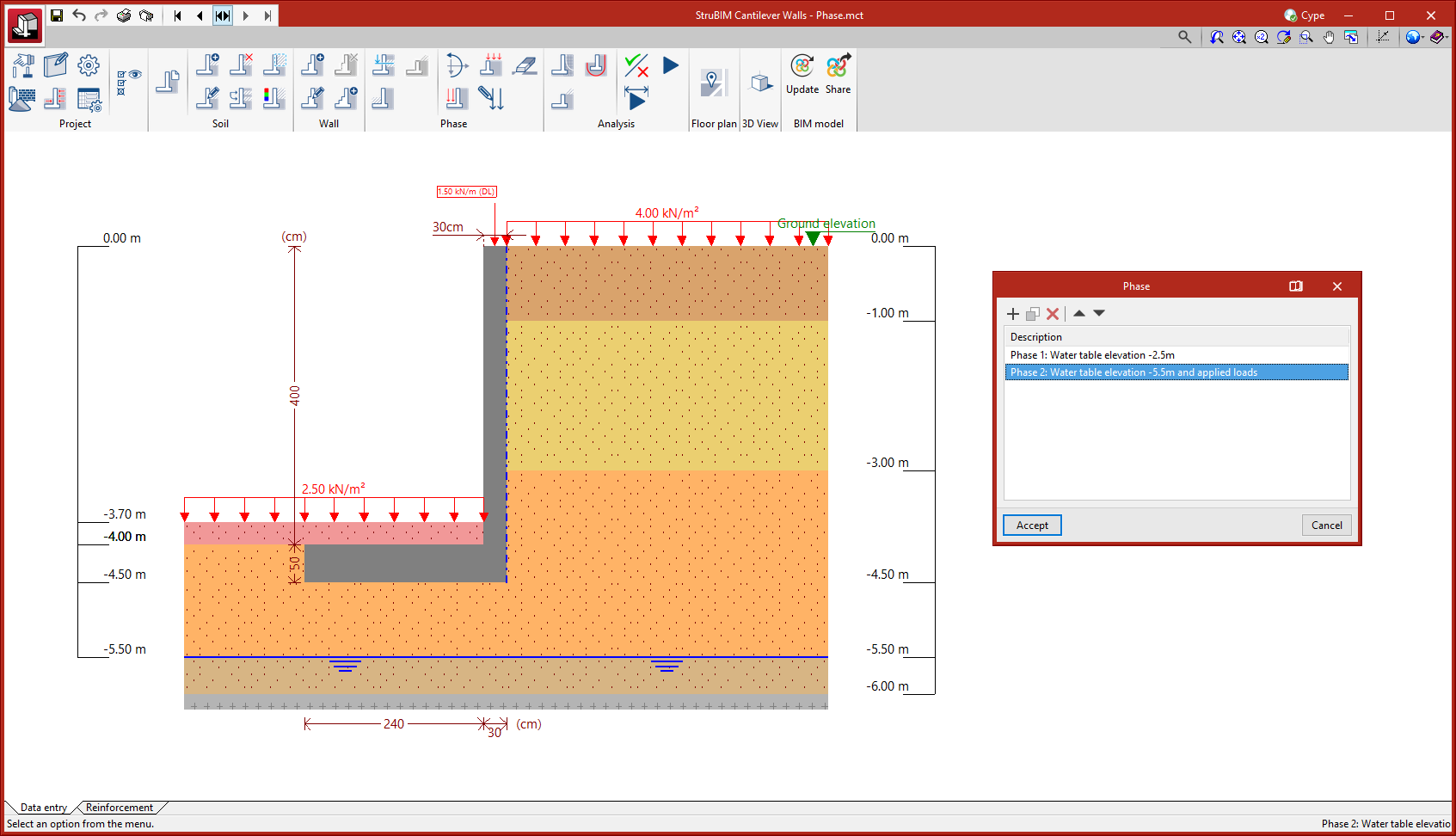
Phases
In the "Data entry" tab, in the "Phase" group of the main toolbar, the data relating to the project phases can be defined:
The menu for defining or switching between different construction phases is located on the left side of the title bar.

Different construction phases or load states can be defined. In each phase, the data of the water table, the fills and the loads can be modified.
The options available are:
- Water table:
Allows users to modify the water table in a given phase. This option is only available if the water table depth has been previously defined for the first phase. - Infill soil:
Allows users to enter the infill soil above the starting elevation of the wall. This option is only available if the "With infill soil" checkbox has been previously activated in the general soil data. - Backfill soil:
Allows users to enter soil above the starting elevation of the wall. This option is only available if the "With backfill soil" checkbox has been previously activated in the general soil data. - Load increment:
Allows users to enter horizontal loads, vertical loads, or moments at the top of the wall or at a given elevation. - New load on the infill:
Allows users to enter loads applied on the soil or on the infill. These can be surface, strip, line, and point loads. - New load on the backfill:
Allows users to enter loads applied on the soil or on the backfill. These can be surface, strip, line, and point loads. - Edit load:
Allows users to modify any load entered, except for top of wall loads, which have their own option. When the load is modified in a specific phase, it is also automatically modified in the rest of the phases where it exists. - Delete load:
Allows users to delete any load entered, except for top of wall loads, which have their own option. When the load is deleted in a specific phase, it is also automatically deleted in the rest of the phases where it exists.
Analysis
In the "Data entry" tab, in the "Analysis" group of the main toolbar, the options required for checking compliance, designing the geometry and reinforcement and analysing the results of each phase are available.

The options available are:
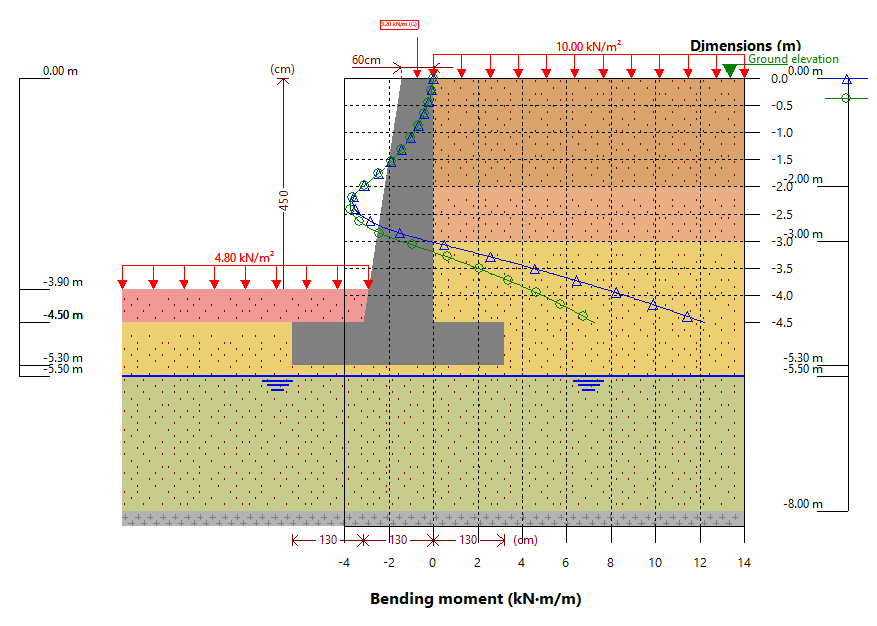
- Phase results:
Draws graphs related to the selected phase on a graduated grid on the screen. - Force diagrams:
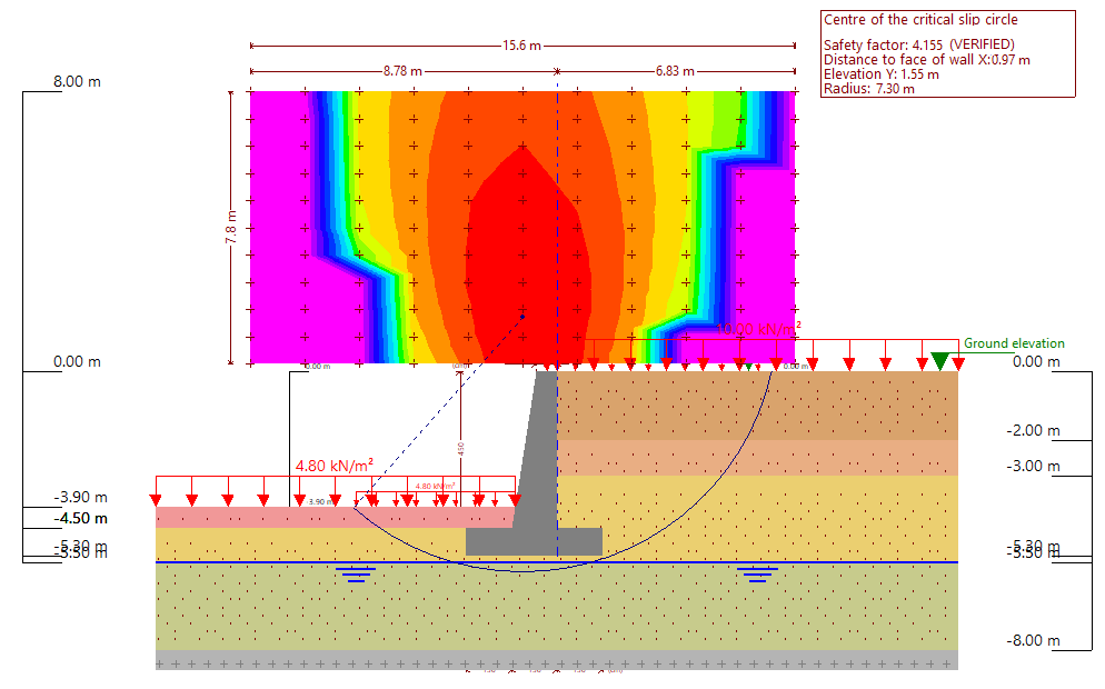
Allows users to consult the graphs of the results for the selected phase. - Critical slip circle:
Analyses and draws the critical slip circle on screen. At the same time, the contour plot map of safety coefficients is drawn on the position of all the analysed slip circles. - Check:
Checks compliance with all requirements for a given geometry and reinforcement or analysed by means of a pre-design. This option does not redesign the reinforcement provided. - Design geometry:
Designs the geometry of the wall. - Design all:
Designs the geometry of the wall for the subsequent design of the reinforcement. After the design, a check is automatically carried out.
Floor plan and 3D view
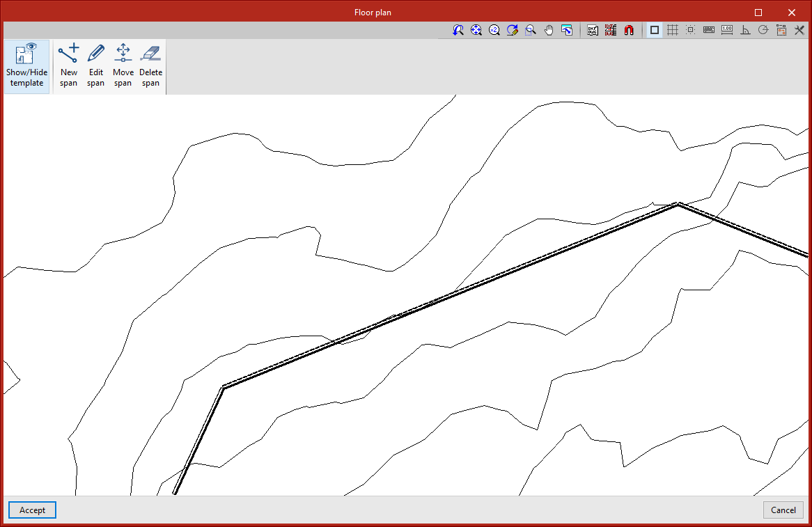
In the "Data entry" tab, in the "Floor plan" group of the main toolbar, the wall outline can be entered so that it is visible with the "3D view" option in the adjoining group.

The options available for floor plans are:
- Show/Hide template:
Enables or disables the display of the template. - New span:
Allows users to create a wall span by configuring some of the parameters. - Edit span:
Allows users to edit the parameter settings of the selected span. - Move span:
Allows the span to be moved from one location to another. - Delete span:
Deletes the span.
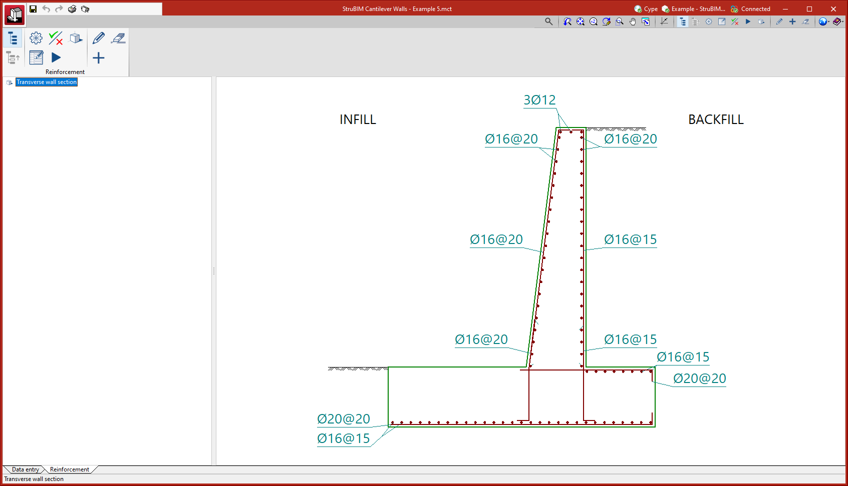
Reinforcement
In the "Reinforcement" tab, in the "Reinforcement" group of the main toolbar, the required options are available to consult the reinforcement, modify it and check its compliance or to carry out an automatic redesign.

The options available are:
- Tree:
Enables or disables the selection tree view. - Up:
Moves up to the next higher level in the selection tree from the element on which the user is positioned. - Options:
Allows users to select the options to be applied in the analysis, such as safety coefficients. - Reinforcement tables:
Allows users to create, modify or use the reinforcement tables included in the program. - Check:
Checks the reinforcement of the selected element. If any non-compliance is found, this is explicitly reported. In any case, whether or not there is any non-compliance, a list of the checks carried out can also be obtained. - Redesign:
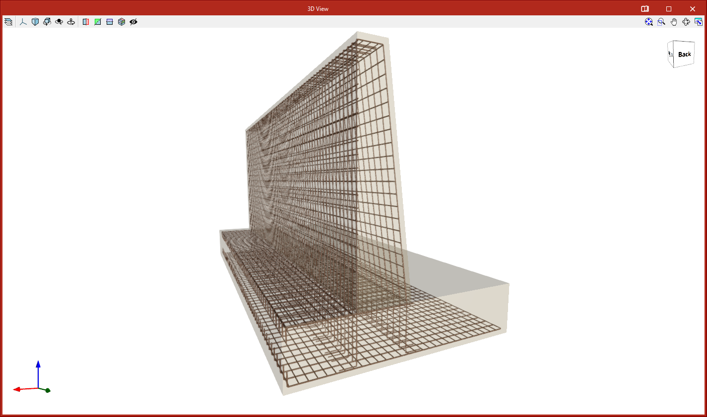
Redesigns the selected element. After completing the redesign, a check is carried out, so if any non-compliance is detected, this is explicitly reported. In any case, whether or not there is any non-compliance, a list of the checks carried out can also be obtained. - 3D view:
Allows the selected element to be displayed in three dimensions. - Edit:
Allows users to edit the reinforcement. - New:
Allows users to enter a new reinforcement. - Delete:
Allows users to delete the selected reinforcement.
Results output
Sheets in DWG, DXF or PDF format
Sheets generated in StruBIM Cantilever Walls can be exported in DWG, DXF or PDF format.
Project reports
The following reports can be exported from models developed in StruBIM Cantilever Walls:
- Code and materials
- Loads
- General data
- Soil description
- Soil profile
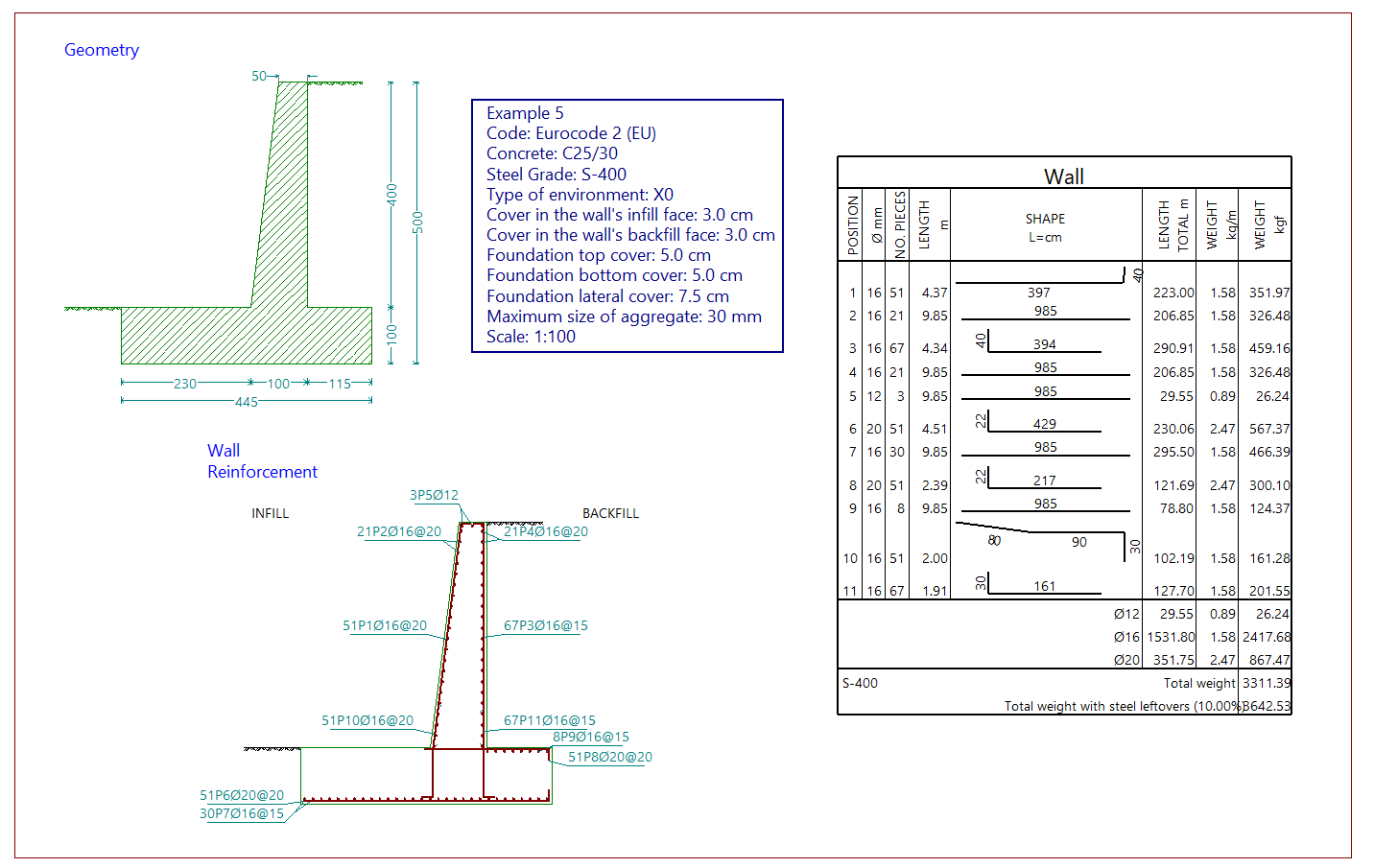
- Geometry
- Phase diagrams
- Loads
- Phase results
- Combinations
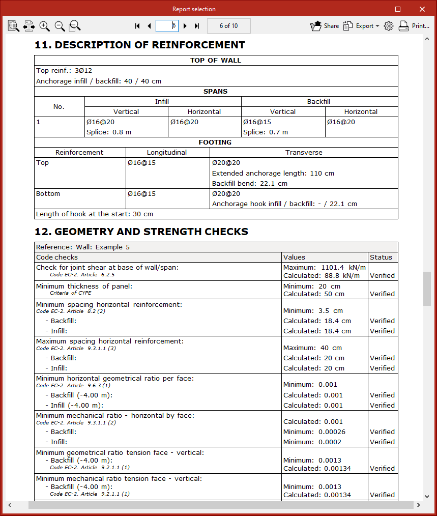
- Description of reinforcement
- Geometry and strength checks
- Stability check (Critical slip circle)
- Quantities
glTF file compatible with BIMserver.center
When exporting the project to the BIMserver.center platform, a 3D model is automatically exported in glTF format for integrating the model of the structure into the Open BIM project, allowing the model to be displayed:
- on the online platform;
- in the BIMserver.center application for iOS and Android;
- in virtual reality and augmented reality;
- in other CYPE programs.
Integration into the BIMserver.center platform
Many of CYPE's programs are connected to the BIMserver.center platform and allow collaborative work to be carried out via the exchange of files in formats based on open standards.
Please note that, to work on BIMserver.center, users can register on the platform free of charge and create a profile.
When accessing a program connected to the platform, the program connects to a project in BIMserver.center. This way, the files of the projects that have been developed collaboratively in BIMserver.center are kept up to date.

Options available in StruBIM Cantilever Walls
In the "Data entry" tab, in the "BIM Model" group of the main toolbar, the required features for using StruBIM Cantilever Walls together with other BIMserver.center tools can be found.

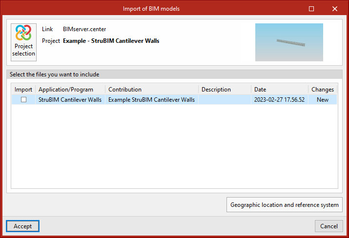
Importing and updating BIM models
The "Update" option allows you to update the information contained in the models previously imported into the project or to import new models if desired.
The import of models is carried out according to the defined configuration and users can choose how new, modified and deleted elements of the BIM model are shared.
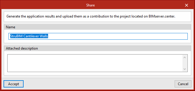
Exporting the BIM model to share it with other users
The information contained in the model developed with StruBIM Cantilever Walls can be exported to BIMserver.center using the "Share" option.
During the export process, users can establish information related to the identification of the files to be exported, the location of the local copies that are automatically generated and the types of files that are generated.
Supported licenses and modules
StruBIM Cantilever Walls has different modules that can be combined to increase the tool's performance.
MUC module: Cantilever walls
The MUC module is the basic module for using StruBIM Cantilever Walls and is a key requirement for running the program as well as acquiring other modules.
MCD module: Calculation of failure planes (global stability)
The MCD module is used for analysing and drawing slip circles in the global stability check.