Introduction
CYPELEC PV Systems is a program for designing and analysing photovoltaic electrical systems. The program has BIM integration resources and can import architectural models generated in IFC format, and offers a library of elements to define the system properties. CYPELEC PV Systems includes an energy design tool that helps users to calculate the number of PV modules required based on energy consumption and solar irradiation data. The system elements, such as solar panels, inverters and batteries, can be entered and the calculation can be made by considering parameters such as orientation, sloping and shading. The program can also be used to define the single-line diagram of the system, calculate the wiring design, generate bills of quantities and obtain detailed results, such as the energy generated, losses and electrical parameters.
Workflows supported by the program
As CYPELEC PV Systems is an Open BIM tool and is connected to the BIMserver.center platform, it offers its users different workflow options.
- Modelling PV systems directly in CYPELEC PV Systems.
- Importing CAD files in 2D, such as DWG, DXF, PDF and JPG, to be used as a reference in the layout of the PV system.
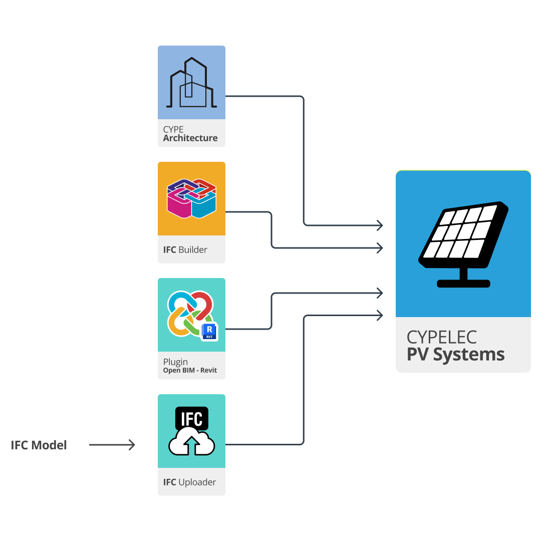
- Importing architectural models developed in BIM via the IFC standard, created with CYPE Architecture, IFC Builder or CYPECAD MEP. These three programs have native connection options with the BIMserver.center platform.
- Importing architectural models developed in BIM, via the IFC standard, created with Autodesk Revit. Both the uploading of the model to the BIMserver.center platform and the downloading of information from the platform to Autodesk Revit is carried out via the Open BIM - Revit Plugin.
- Importing architectural models developed in BIM via the IFC standard from other architectural modelling programs, such as Archicad or Allplan, among others. The model is uploaded to the BIMserver.center platform using the IFC Uploader application.
Work environment
The work environment in CYPELEC PV Systems is similar to that of other CYPE modelling programs.
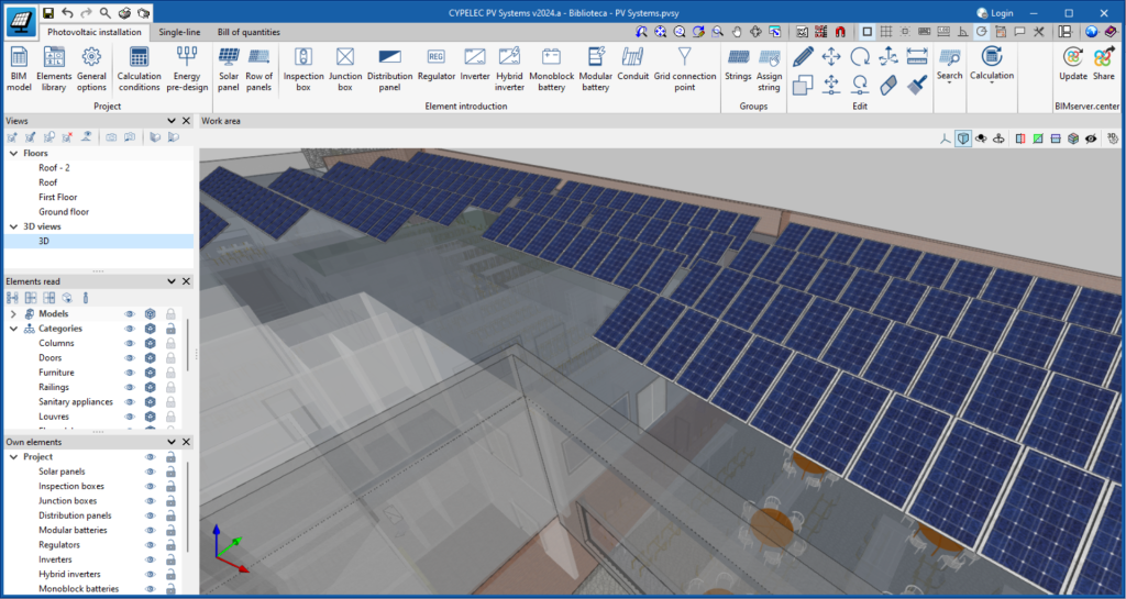
The top toolbar contains the main tools for creating project libraries, modelling and entering the main elements of the system, managing groups and connecting to the BIMserver.center platform.
The model viewing area can be found on the right-hand side of the interface and allows the system to be modelled and all the elements of the project to be viewed in 3D, including both the models entered in the program and the models read from other applications.
The left-hand side contains the main tools for defining the views of the system and managing the visibility of both elements read and own elements.
Element library
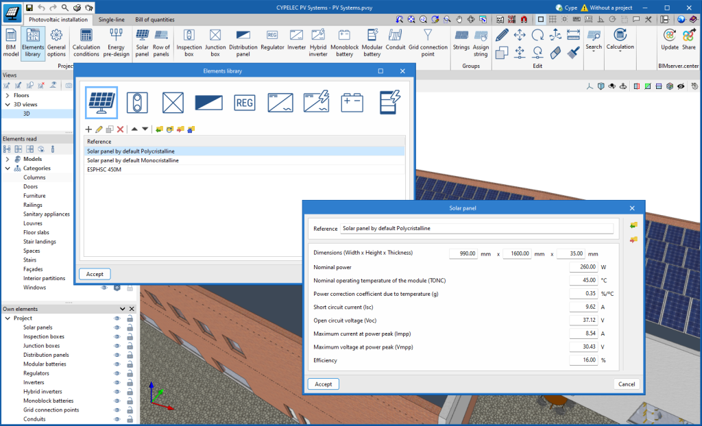
Before starting to design the system, the application has an element library users you can define the properties of the units that are going to be used. These libraries are oriented towards the integration of elements from manufacturers.
Energy pre-design

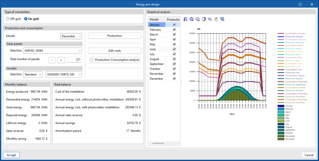
Before starting to enter the elements, the program has an integrated tool to estimate the number of photovoltaic modules needed for future installation. This is a pre-design that requires the following data to be provided:
- The estimated or actual electricity consumption, obtained from the data provided by the energy supplier.
- The irradiation data of the site and the orientation and slope of the PV panels. Irradiation data can be provided by various sources, such as PVGIS (Photovoltaic Geographical Information System).
Entering the above data allows you to select the type of system. The following combinations can be selected:
- Off-grid system with monoblock batteries.
- Off-grid system with modular batteries.
- On-grid system without storage.
- On-grid system with storage and autonomy.
- On-grid system with surplus storage.
Calculation conditions

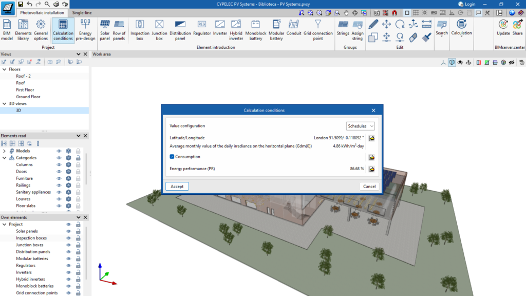
The "Design conditions" option is used to enter the basic parameters of the system, the location and the irradiance or irradiation values (depending on whether the user wants to work with hourly or total values) in the horizontal plane. Furthermore, consumption values can be entered, if available.
Based on the geometrical configuration of the entered PV modules, the program analyses the orientation and slope losses. Losses due to shading are obtained based on the shadows cast by the architectural elements of the linked project, the solar panels themselves, nearby buildings and other obstacles in the surroundings.
Single-line diagram
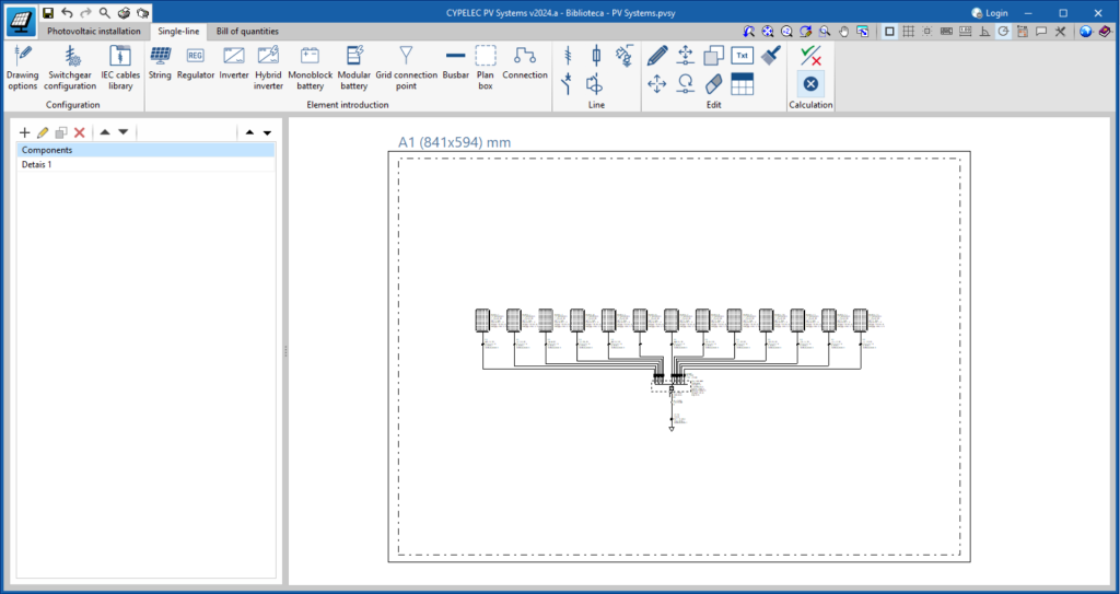
The program allows users to draw the single-line diagram of the system in the "Single-line" tab, located in the top left-hand corner of the main window.
In this diagram, the elements will have their electrical parameters and will be connected by means of conduits, where the type of cable with its characteristics and fittings will be defined.
This way, once the single-line diagram has been defined, the program will analyse the electrical parameters of each of the conduits and carry out the following checks based on the international IEC standard:
- Allowable current.
- Coordination amongst conductors and overload protection devices.
- Voltage drop.
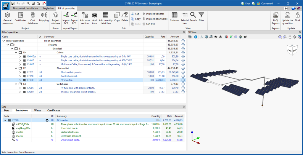
Bill of quantities of the system
Results output
Drawings in DWG, DXF or PDF format
Drawings generated in CYPELEC PV Systems can be exported in DWG, DXF or PDF format.
Drawings created in the "Single-line" tab, along with other drawings generated from the model views of the PV system, can be exported.
Project reports
The following reports can be exported from a model that has been created and analysed in CYPELEC PV Systems from the "Reports" option in the top left-hand corner of the interface:
- Justification calculations.
- Production summary.
Furthermore, from the "Consult results" option in the "Analysis" group, users can consult results reports for each selectable element in the viewer, both in the "Photovoltaic installation" tab and in the "Single-line" tab.
The program displays the following results:
- Energy produced by each solar panel and by the whole set.
- Loss due to orientation or inclination.
- Loss due to shading.
- Loss due to temperature.
- Sections needed in the cables to support the currents generated in each section and not to exceed the maximum voltage drop value permitted.
- Power, voltage and current values admitted by the inverter depending on the configuration adopted.
- Power and voltage values permitted by the regulator.
IFC and glTF files, compatible with BIMserver.center
Exporting the project to the BIMserver.center platform will automatically export a 3D model in IFC and glTF format for integrating the model of the structure into the Open BIM project, allowing the following:
- viewing the model on the online platform;
- viewing the model in the BIMserver.center application for iOS and Android;
- viewing the model in virtual reality and augmented reality;
- viewing the model in other CYPE tools;
- integrating the model in the project and compatibility with the rest of the project's disciplines with Open BIM Model Checker.
Integration into the BIMserver.center platform
Many of CYPE's programs are connected to the BIMserver.center platform and allow collaborative work to be carried out via the exchange of files in formats based on open standards.
Please note that, to work on BIMserver.center, users can register on the platform free of charge and create a profile.
When accessing a program connected to the platform, the program connects to a project in BIMserver.center. This way, the files of the projects that have been developed collaboratively in BIMserver.center are kept up to date.

Licenze e moduli correlati
Il software CYPE viene attivato mediante licenze elettroniche che possono contenere uno o più moduli. L'elenco dei moduli compatibili con ciascun programma può variare a seconda del prodotto acquistato e del tipo di licenza.
Per consultare l'elenco dei moduli compatibili con questo programma, si può accedere a “Moduli dei programmi CYPE”.
È importante tenere presente che l'elenco dei moduli disponibili nella licenza dipende dal prodotto acquistato.

