Modelling connections
Within the "Model" tab, users can enter a list of operations that are used sequentially to define the elements and geometry of the connection.
The entry order and the nomenclature used to identify each operation directly affect the way in which the connections are generated. During the modelling process, the program displays warnings about possible incompatibilities between modelled elements.
The connection editor is used to organise the list of operations by including groups of operations with an icon to identify each operation in the list.
It also has an option bar that includes several features.
- The "New group" option adds a new empty operation group. When a group is selected, new operations are added within this group. To insert or move an existing operation into or out of a group, use the tools to move up or down, depending on the position. Operations can also be dragged and dropped into or out of a group. This feature allows moves operations or groups of operations to another position, allowing an operation to be moved directly to the desired position without having to go through the intermediate positions one by one. Groups of operations can be expanded or collapsed, to either display or hide the operations they contain.
- A group of operations can be activated or deactivated by ticking the box on the left-hand side of the name for each group, which will affect all the operations included in the group.
- "Move up" moves the selected operation or group to the top of the list.
- "Move down" moves the selected operation or group to the end of the list.
- "Search" is used to search for operations by text.
- "Delete all the elements from the list" deletes all operations and groups of operations from the list.
- "Copy", with a group selected, is used to copy the group with all its operations.
- "Delete" is used to delete the group and all the operations it contains, or to delete the group and keep the operations ungrouped.
- "Export selected transactions to library", if you have a group selected, exports all the transactions contained in that group.
The main toolbar in this group allows the following operations to be carried out:
Reference plan | Reference plans are used to make cuts in sections and plates, to make extension or reduction adjustments to these plans, or as a reference when adding plates. | |
Bar | This tool allows additional bars to be added to the connection in order to create drops, support elements, reinforcement for corbels, etc. | |
Plate | This tool allows rectangular and polygonal plates to be generated. Polygonal plates can be defined from coordinates (tables can be copied and pasted directly from spreadsheets). | |
Adjust bar | This operation allows a bar to be lengthened or shortened by fitting it to another bar, a reference plane or a plate. It also allows welds to be generated after this fitting. | |
Trim section | This operation makes it possible to create a trim on the selected section according to the "x" and "y" magnitudes entered. The type of trim can also be defined: straight, with a chord radius or with drill. | |
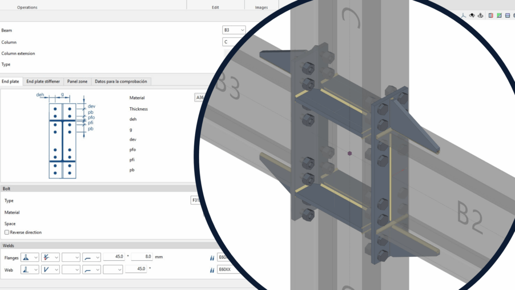
End plate | This operation allows one section to be joined to another by means of an end plate. Welds can be entered from the section to the plate and bolts can be entered between the plate and the section. | |
Lateral plate | Allows sections to be joined together by means of a plate welded to one section and bolted to the other. | |
Trim plate | This operation allows a plate to be trimmed from another element. The trim can be carried out from the face of a bar, from a previously defined reference plan or from another plate. | |
Modify corners | Allows users to define bevel, chamfer, notch, round and arc cuts at the corners of the plates. | |
Move | Allows bars or plates to be moved using another element as a reference. | |
Bolts | This operation is used to enter bolts into the connection. Two elements to be bolted must be selected. If more than two are selected, the end elements of the connection must be indicated. | |
Weld | This operation is used to enter welds between two elements. Both "Fillet", "Butt" and "Lap" welds can be created. | |
Opening | This operation allows openings to be created in sections or plates. The openings can be circular or polygonal. | |
Concrete | This operation allows concrete elements to be entered into the connection. Where necessary, anchors will be applied on top of them. | |
Anchors | This operation is used after a plate has been entered and allows anchors to be added to the plate. Anchors are entered in the same way as the bolts. | |
Stiffeners | This operation is used to enter the stiffeners via a wizard where their material, geometry, position and welds are defined. | |
Timber | This operation is used to insert fasteners used in timber bars. It allows users to enter dowels, bolts and screws for timber. This feature is only available in CYPE Connect. |
As well as the operations already mentioned, the program offers other additional tools to make the modelling of the connection easier:
Reference: can be automatic or user-defined. The automatic reference is made up with the prefix defined in the sheet generation options. This feature is only available in StruBIM Steel.
Modelling options: allows users to edit the representation lengths and the analysis of the sections. For sections with curved segments, the program can analyse an optimal number of sides when discretising these segments or they can be chosen manually.
View options: allow the view of the elements to be configured so that they are displayed opaque or transparent, with or without reference axes, with or without labels and with or without the volume of the envelope.
Measure: allows measurements to be taken by selecting the elements of the connection.