Introduction
StruBIM Steel is a program for carrying out structural steel detailing. This program includes different tools for modelling or importing a BIM model and allows users to accurately define all the elements required for the detailing, such as sections, plates, bolts, welds and anchors. As a result, the application provides manufacturing files in DSTV format.
Workflows supported by the program
As StruBIM Steel is an Open BIM tool and connected to the BIMserver.center platform, it offers different workflow options.
- Modelling steel structures directly in StruBIM Steel
- Importing a steel structure designed in CYPECAD
- Importing a steel structure designed in CYPE 3D
- Importing models of steel structure in IFC format
- Importing structures from an XML file generated by ETABS®
- Importing structures from an XML file generated by SAP2000®
- Importing structural models and their forces from JSON files generated by any program

| Note: |
|---|
| In addition to the various possibilities mentioned above, StruBIM Steel includes the same tools as CYPE Connect as part of its connection modelling options. This provides another interesting interaction between the two programs, allowing users to save connections created in CYPE Connect to a local user library and then import them into StruBIM Steel, or vice versa. |
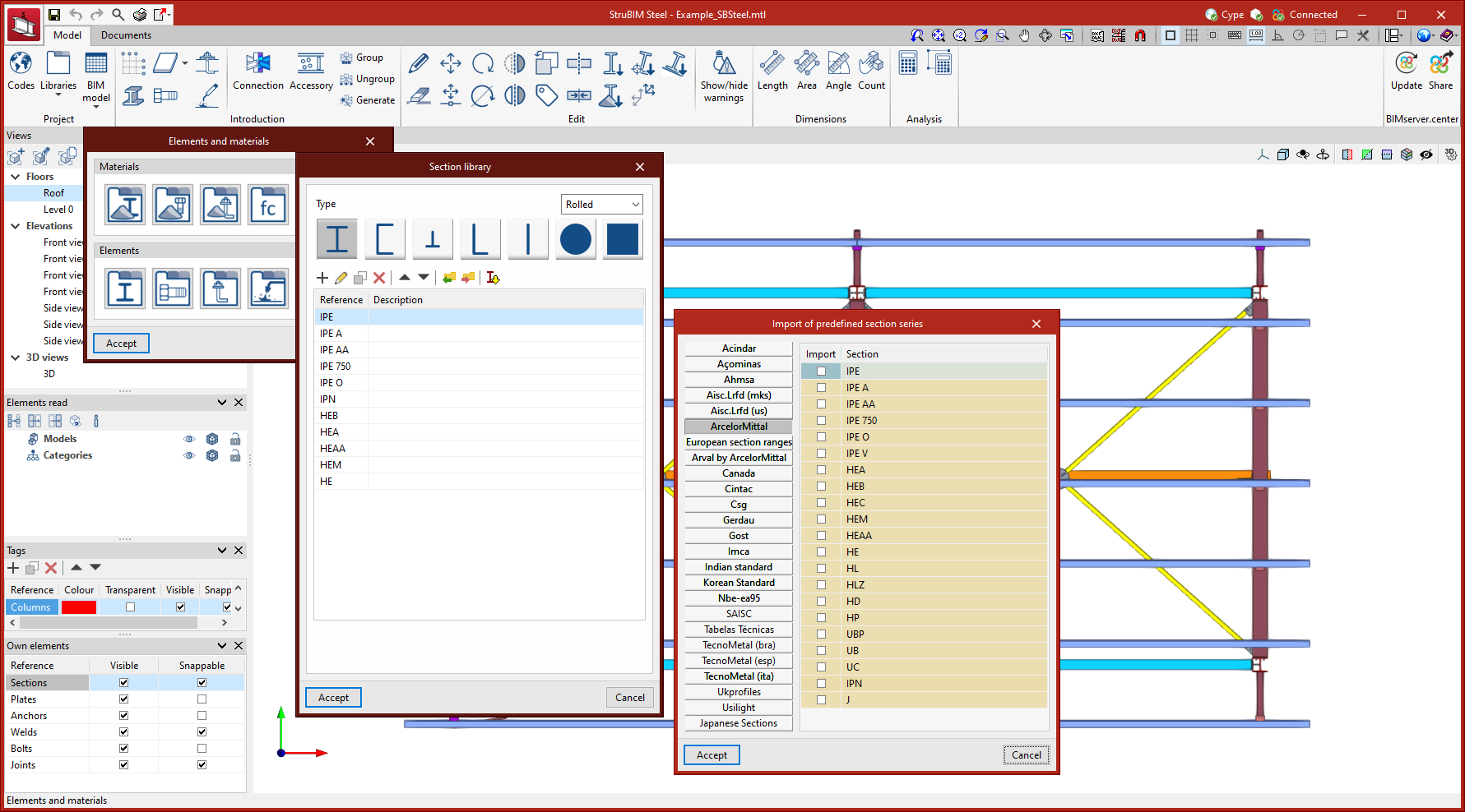
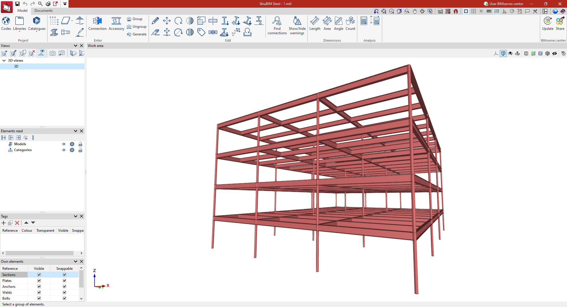
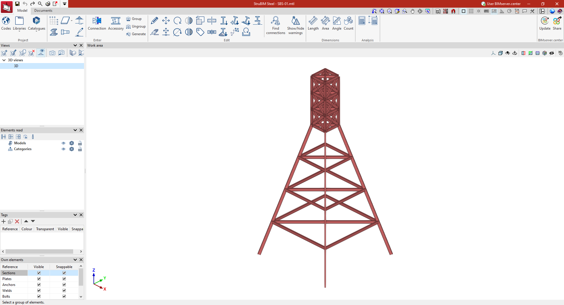
Working environment
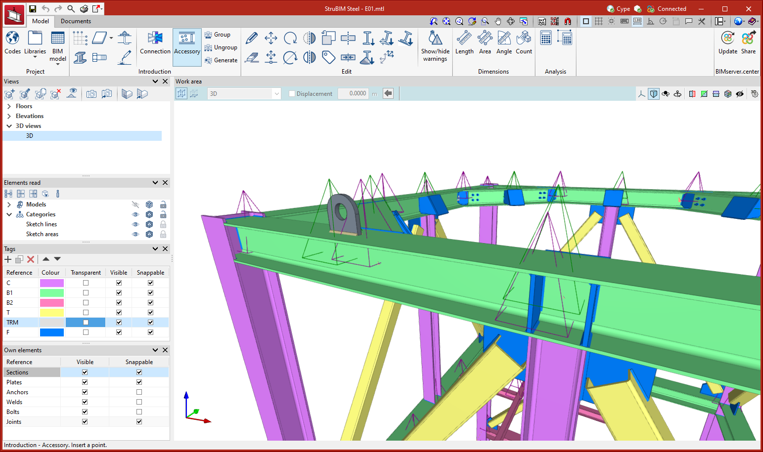
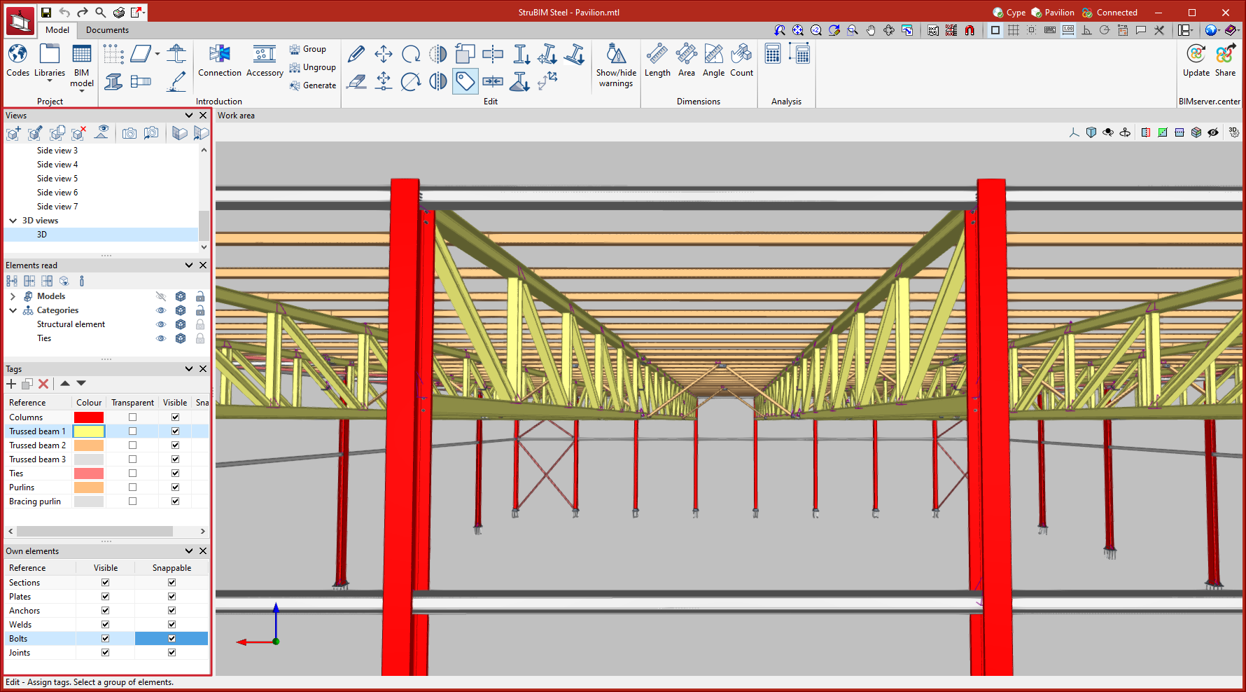
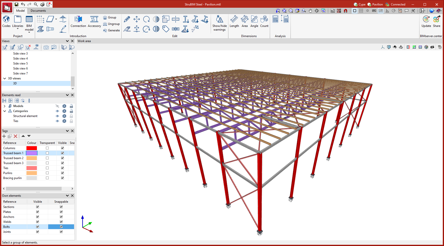
The StruBIM Steel working environment is similar to other CYPE modelling tools and features a system of dockable windows that can be customised to adapt the workspace to the project's needs.
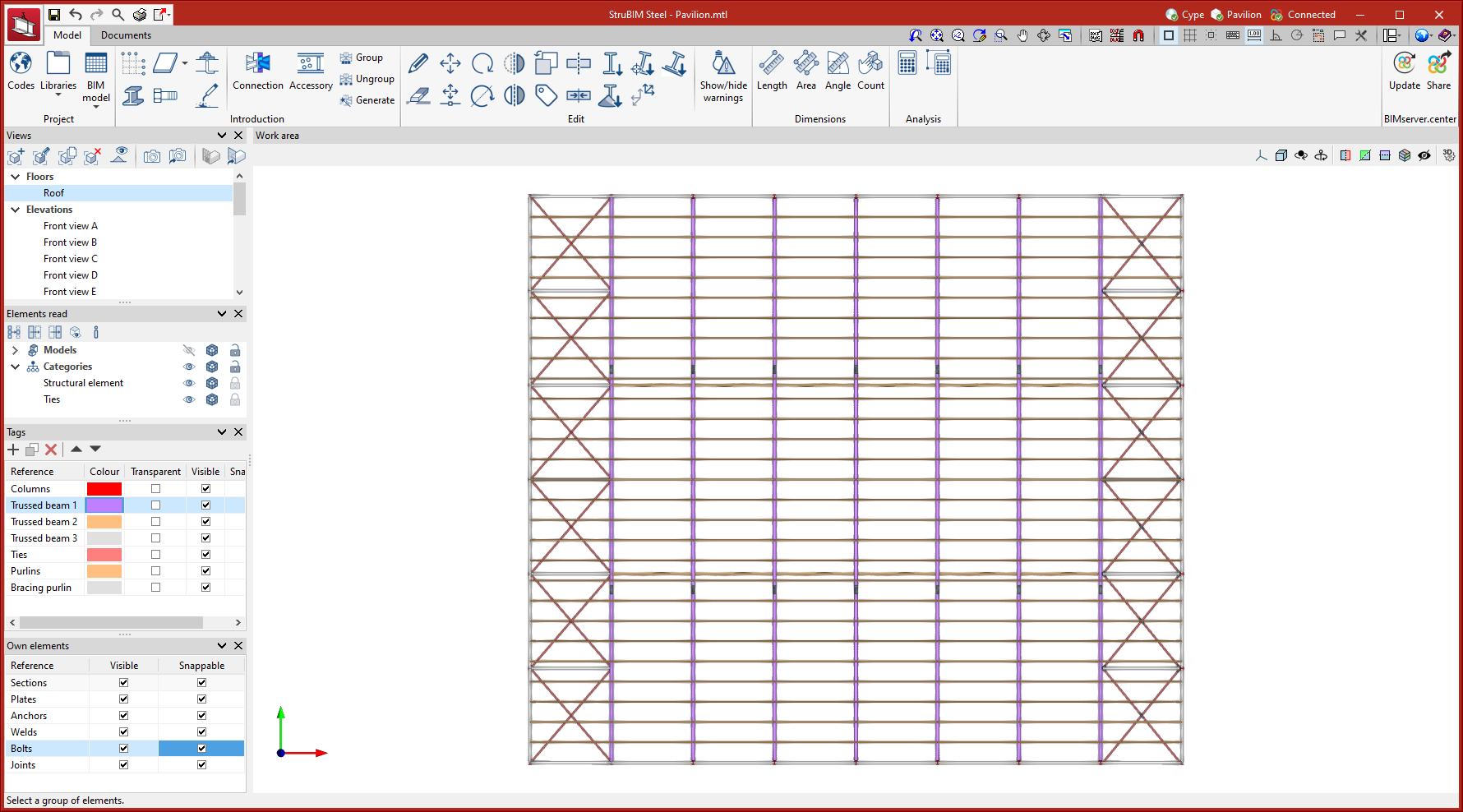
At the top left of the screen, there are two separate tabs: "Model" and "Documents".
The modelling area is located on the right-hand side of the start screen and is where all elements of the project are entered, edited and visualised in 3D
The main toolbar contains different features depending on the "Model" or "Documents" tab. You can create project libraries, enter or edit elements, measure model elements, analyse connections, and also number and manage sheets.
The left-hand side contains the main tools for defining the project views, managing the view of the elements read, the tags and the elements themselves.
Defining the project characteristics

In the main toolbar, in the "Project" group, the following project data can be defined:
Selecting the code used in the connection analysis
As an alternative to the detailing of the connections that can be performed in StruBIM Steel, the program also offers users the possibility to analyse the connections using CYPE Connect, which works together with StruBIM Steel, as long as both programs are included in the license. In this case, the selection of the design codes for the different project materials is carried out from the "Codes" window.

Codes available in the program
| More information: |
|---|
| You can consult the wide range of codes included in CYPE programs by clicking on this link. |
Materials library
StruBIM Steel allows the characteristics of the materials used in the project to be saved via the following libraries:
Types of steel for sections and plates
The steel required for manufacturing the sections and sheets of the project can be saved in the program's library by entering the reference, description, modulus of elasticity, Poisson's ratio, coefficient of thermal expansion, unit weight, yield strength and fracture limit. There is also the option of detailing the resistance criteria depending on the thickness of the material.
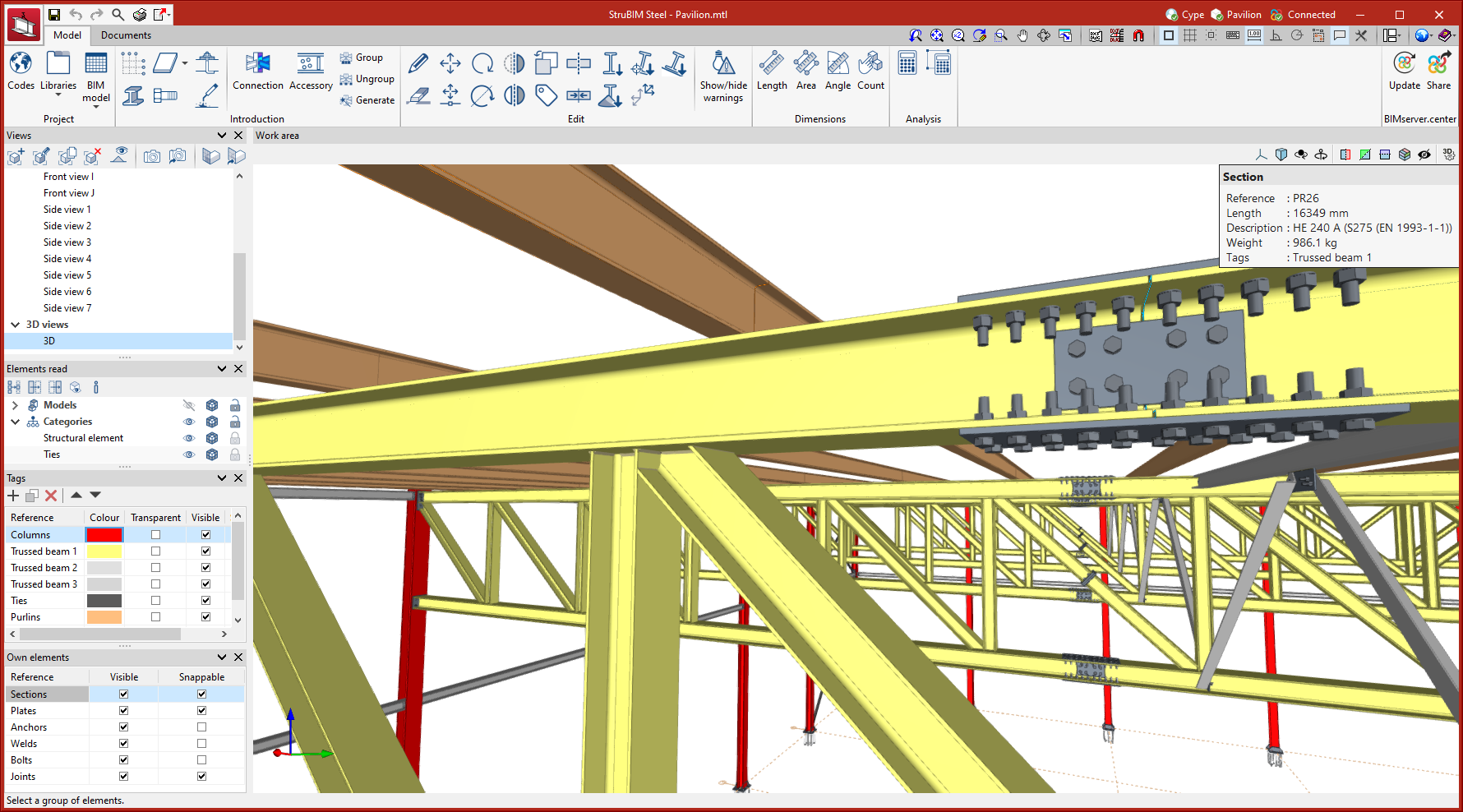
Types of steel for bolts
The steel required for characterising the bolts in the project can be saved in the program's library by entering the reference, description, modulus of elasticity, Poisson's ratio, coefficient of thermal expansion, unit weight, yield strength and fracture limit. There is also the option of detailing the materials of the nuts and washers.
Types of steel for anchors
The steel required for characterising the anchors of the project can be saved in the program's library after entering the reference, description, modulus of elasticity, Poisson's ratio, coefficient of thermal expansion, unit weight, yield strength and fracture limit. There is also the option of detailing the materials of the nuts and washers.
Types of concrete
The types of concrete used can also be saved in the program library. To do this, the reference, description, compressive strength, compressive strain in the concrete at maximum stress and the ultimate compressive strain of the concrete must be entered.

StruBIM Steel allows the characteristics of the materials used in the project to be saved via the following libraries:
Elements library
StruBIM Steel allows users to save the characteristics of project elements via the following libraries:
StruBIM Steel permite guardar las características de los elementos del proyecto a través de las siguientes bibliotecas:
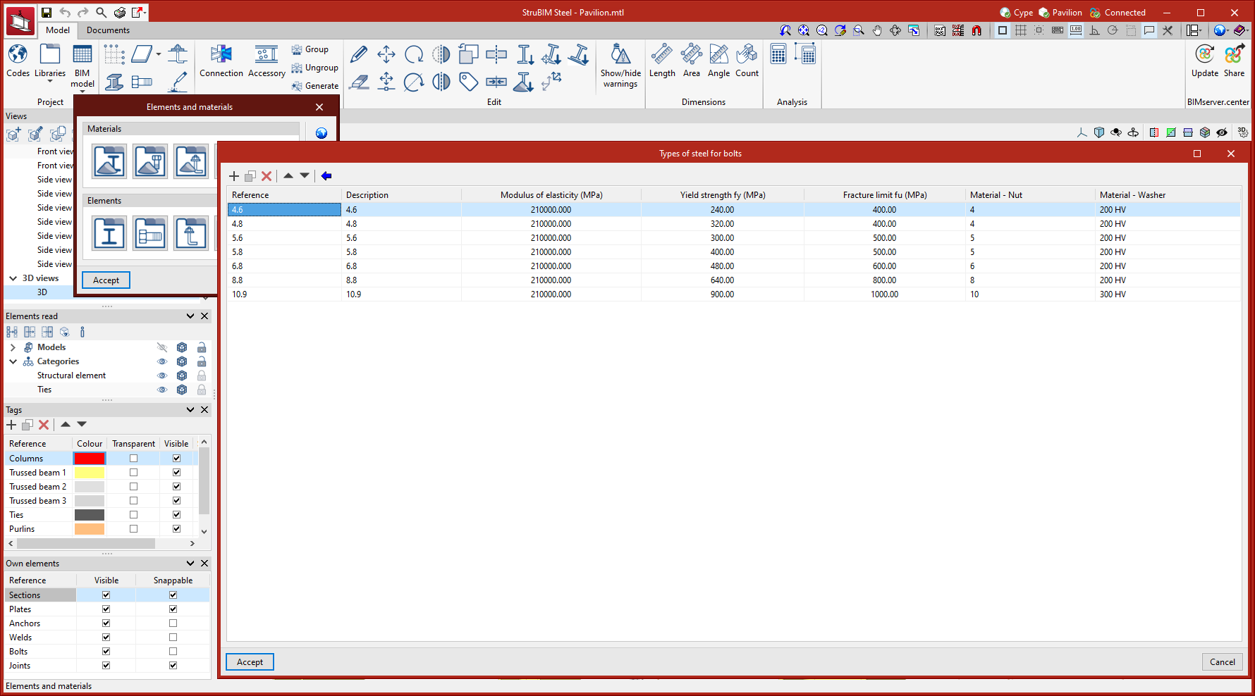
Section library
The StruBIM steel sections library allows users to enter rolled, reinforced, cold-formed and tubular steel sections of various types. As well as manually entering sections, StruBIM Steel allows information to be retrieved from an extensive section library, with codes and manufacturers from a wide range of countries.
Bolt library
The StruBIM Steel bolt library allows series of bolts to be stored depending on different geometrical characteristics. Each series can also be characterised by entering a reference, whether or not there is a locknut, whether or not the bolt is pre-stressed, and the number of washers. As well as manual bolt entry, StruBIM Steel has an extensive library of bolts including standards from a wide range of countries.

Library of cast-in anchors
The StruBIM Steel cast-in anchor library allows series of anchors to be registered, considering different geometrical characteristics. As well as manual anchor entry, StruBIM Steel allows data to be retrieved from an anchor library including standards from a wide range of countries.

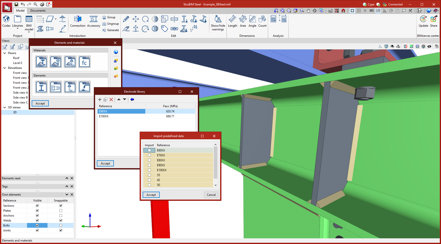
Electrode library
The StruBIM Steel electrode library allows electrodes to be saved by entering a reference and resistance. As well as manual electrode entry, StruBIM Steel allows data to be retrieved from an electrode library covering different types of electrodes.
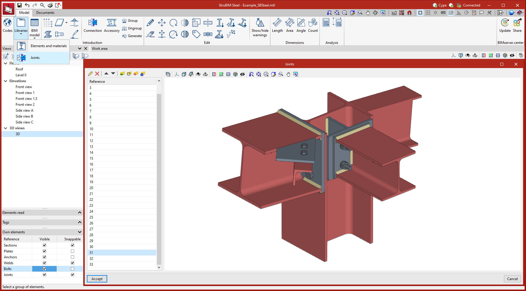
Joints library
Joints between structural elements modelled in StruBIM Steel can be saved in a local library and reused in other projects. This library is compatible with CYPE Connect.
Entering elements
In the "Introduction" group of the main toolbar, the main features for entering reference elements, modelling the structure and entering connections can be found. Some of these tools are common to other CYPE programs.

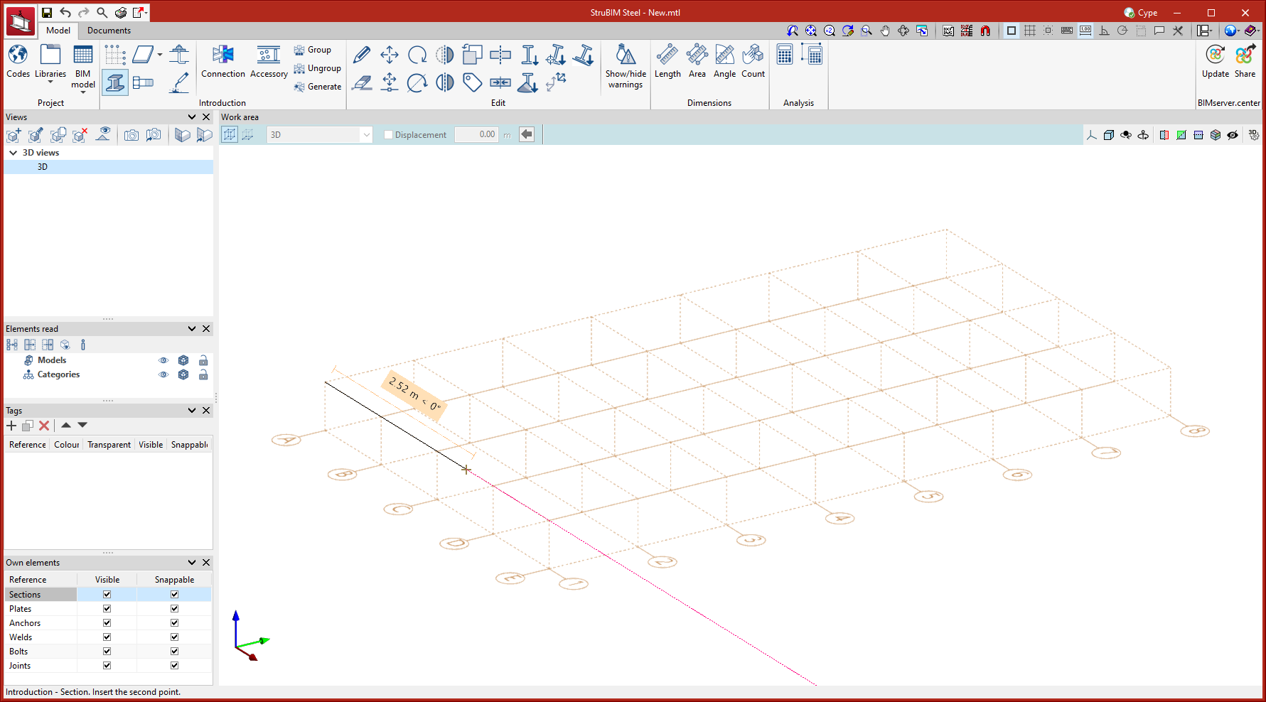
Grid
Grids are reference lines that make the geometrical modelling of the structure easier. They can be used during the modelling phase to draw any element, as they can be snapped, just like any other element in the model. Grids and reference lines are particularly useful for placing the bars of a modular structure, or for projects that are being 100% developed in StruBIM Steel without prior import.
| More information: |
|---|
| The reference grid is a tool available in several CYPE programs. To see an example of how to enter a grid, you can watch this CYPE Architecture video. |
Modelling of the structure
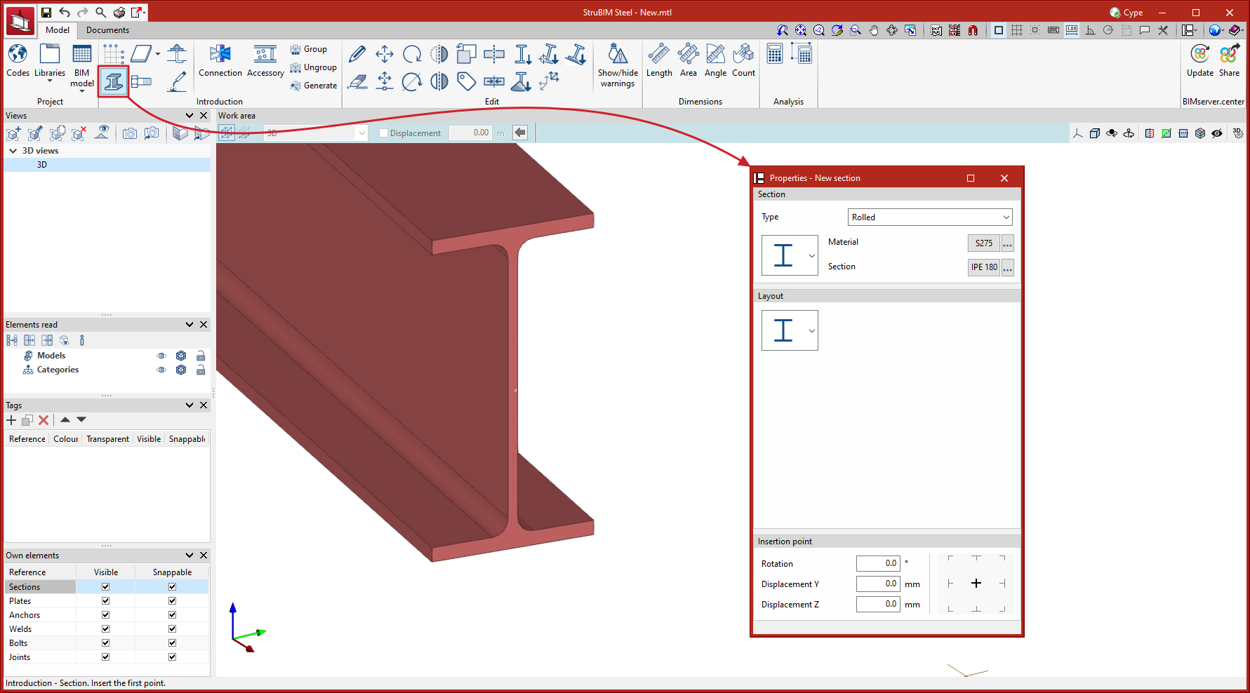
Entering sections
When entering a section, the different characteristics of the section are configured in the selection panel and will be available depending on the data stored in the previously created or loaded steel section library.
When entering a section, selecting the type, material and profile section and, in some cases, its layout, is necessary. To make modelling easier, the characteristics of the insertion point can also be set, selecting the alignment condition (left, centre, right, among others), and applying rotations and displacements.
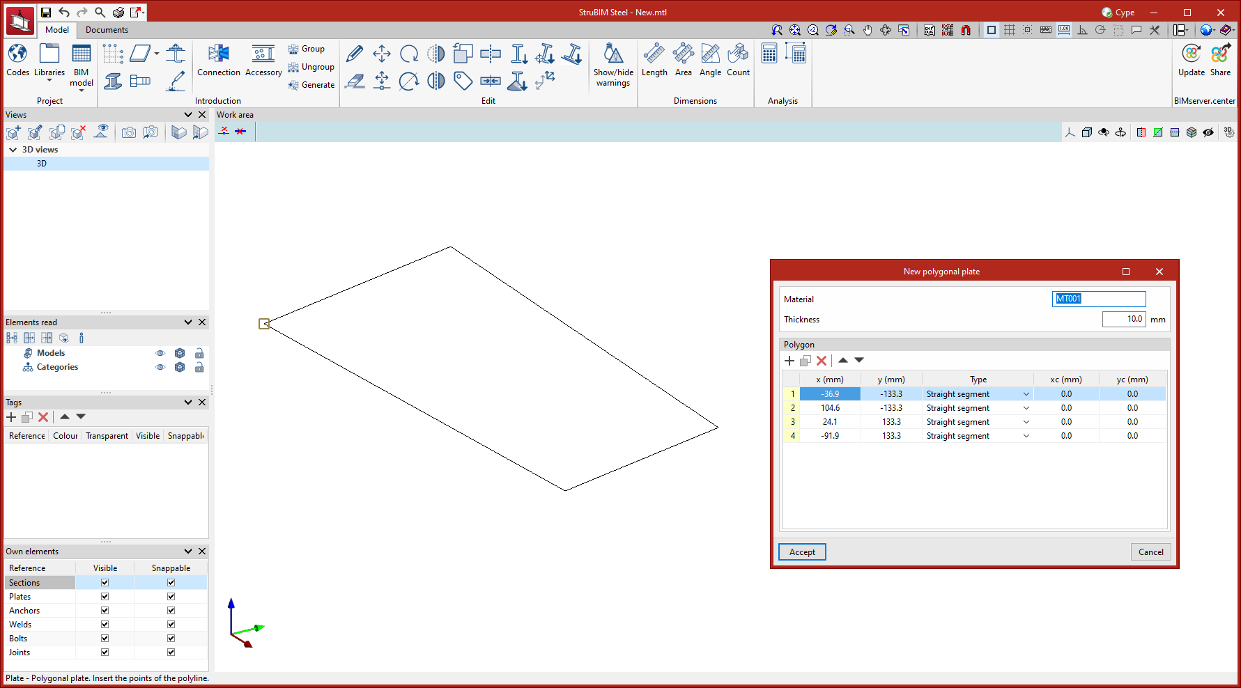
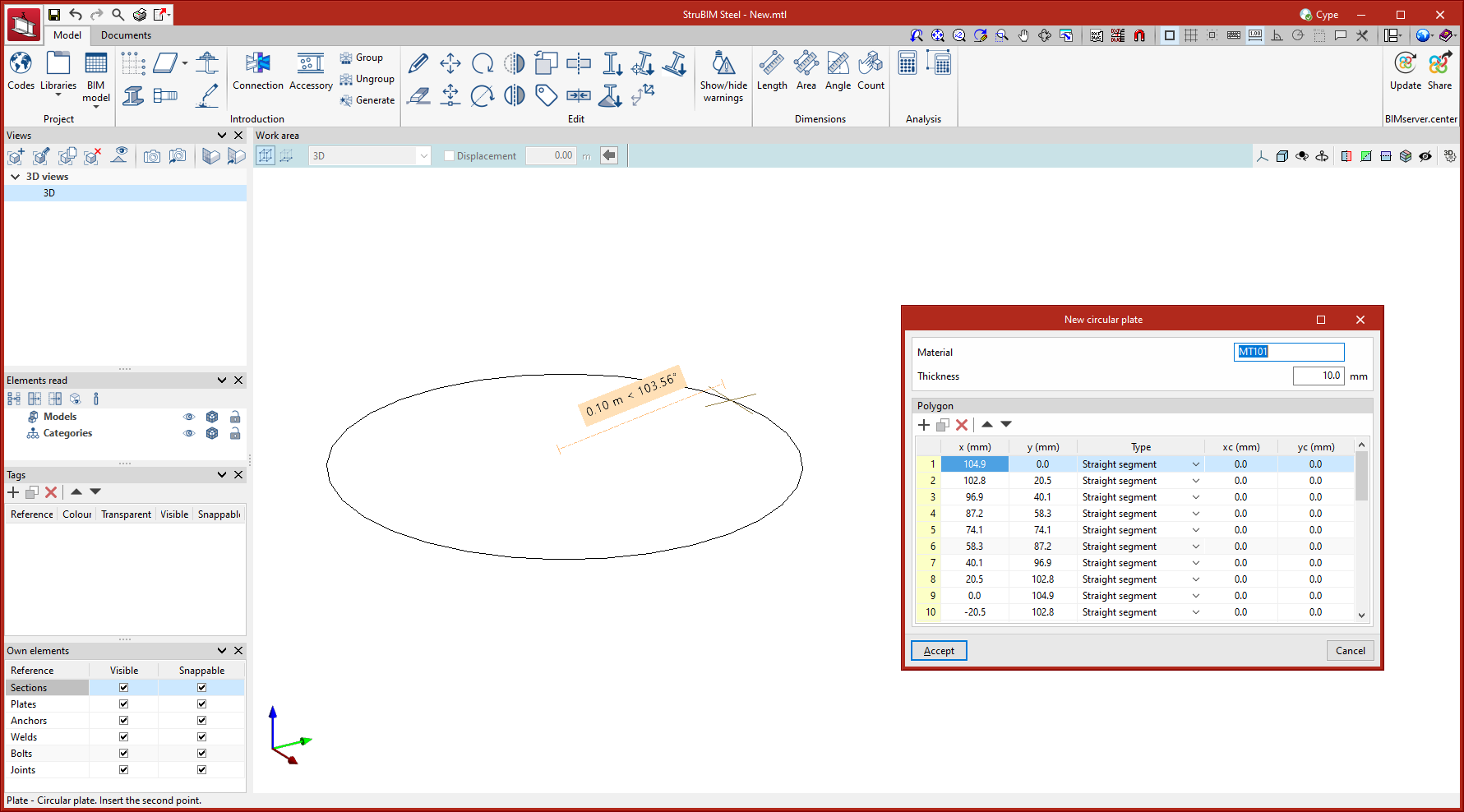
Entering plates
Plates can be modelled in two ways:
To enter polygonal plates, simply enter the vertex points that make up the polygon of the plate.
To enter circular plates, simply enter the radius of the plate.
Once the plate's geometry has been defined, the thickness and material of the element need to be established.
| Note: |
|---|
| All modelling tools, such as object snaps, DXF/DWG template object snaps, grids, orthogonality, polar tracking, etc., can be used to make plate modelling easier. |
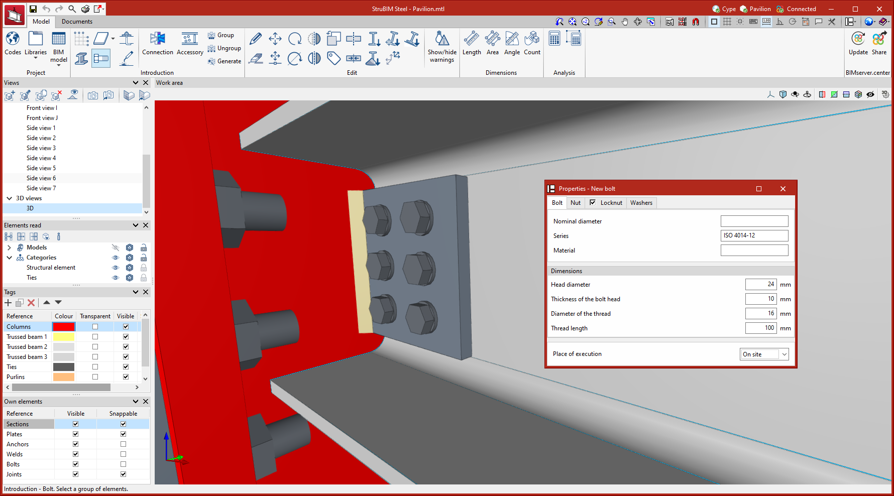
Entering bolts
To enter a bolt, the material and geometric characteristics, nuts, locknuts and washers must be selected. It is also possible to define the place of execution, choosing between "On site" and "At workshop".
Entering anchors
To enter anchors, the material and geometric characteristics of the anchor must be selected, as well as the characteristics of the nuts and washers, if any. The place of execution can also be defined, choosing between "On site" and "At workshop".

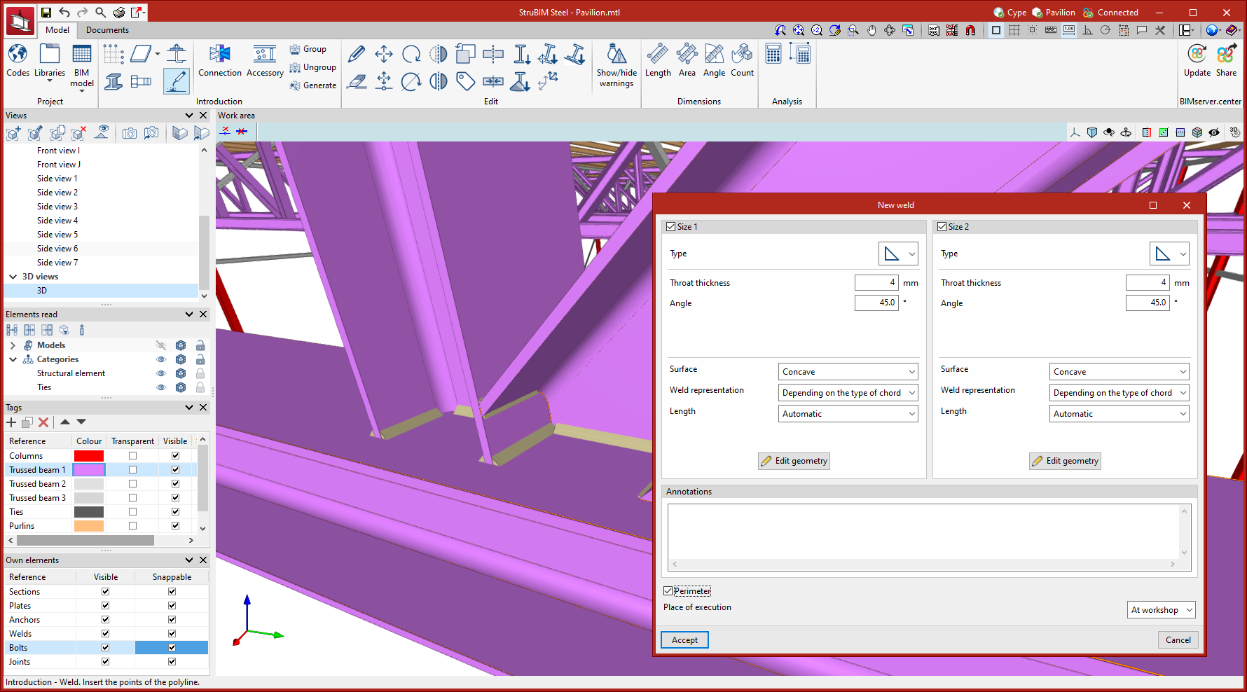
Entering welds
To enter welds, users must select two or more elements to be welded and then draw a line indicating the position of the fillet weld. In the welding configuration window, the different characteristics of the weld are defined, selecting the geometric properties, type of material, type of surface area and type of graphic representation for each side. The place of execution can also be defined, choosing between "On site" and "At workshop".
| Best practice: |
|---|
| If at any stage of the modelling, the objective is to make connections between bars of the structure, it is advisable to use the "Connections" tool. It is recommended that the modelling tools for plates, bolts, anchors and welds be used separately to complement the detailing at specific points of the structure. |
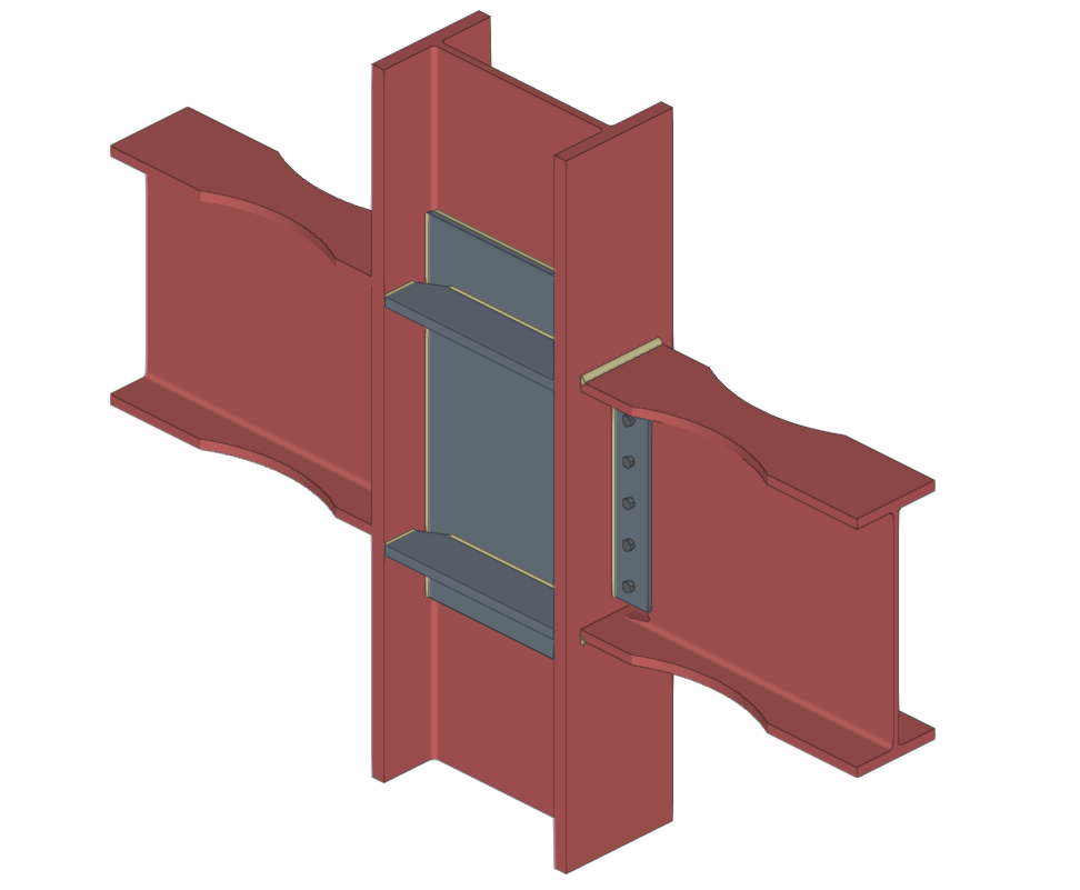
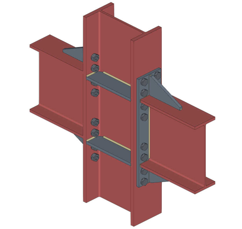
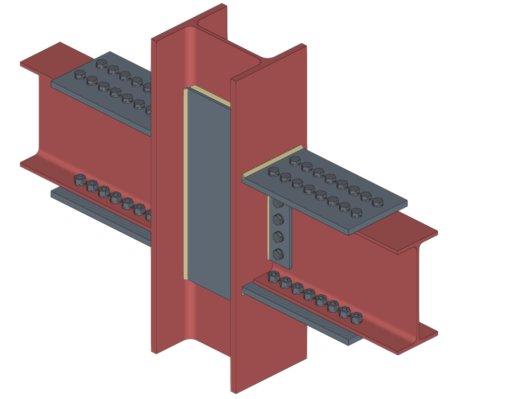
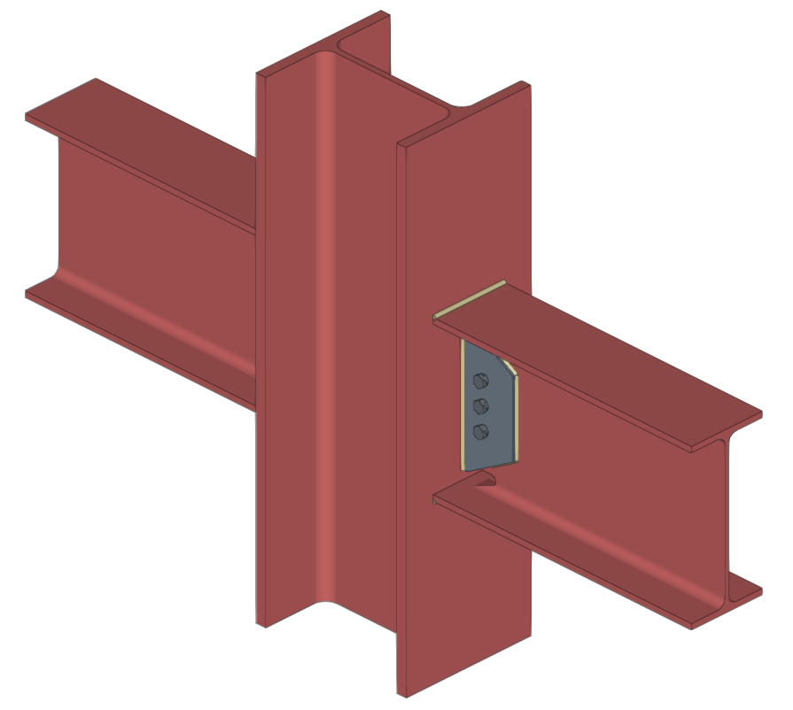
Modelling, analysis and graphical information of connections
Types of connections
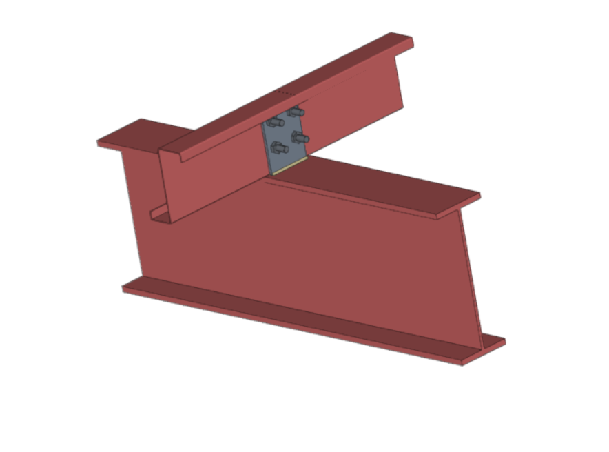
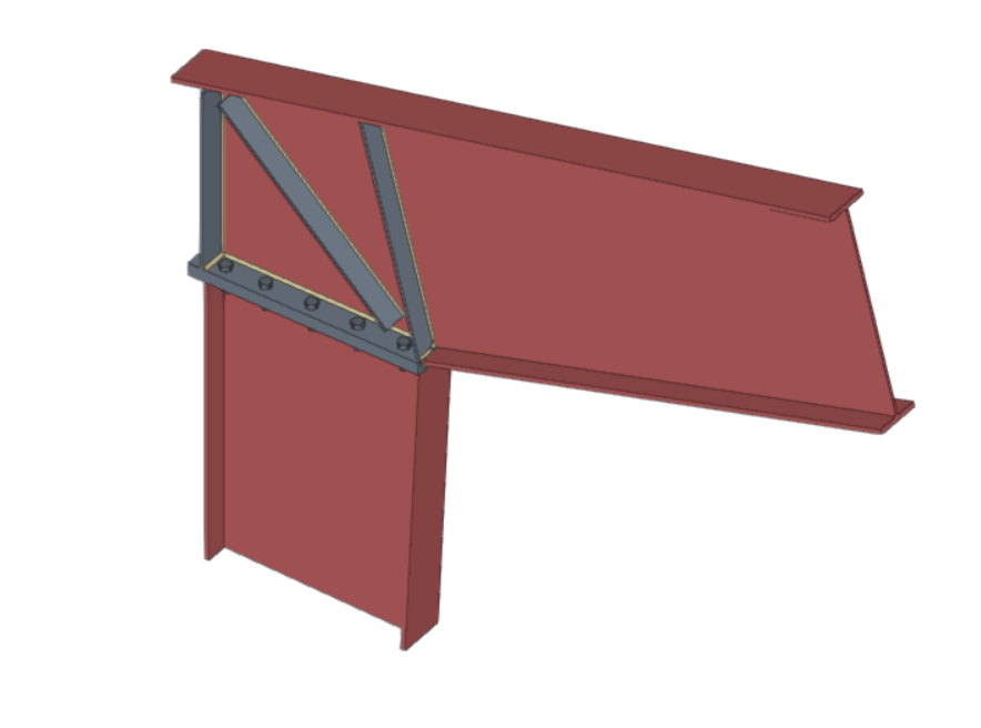
StruBIM Steel offers a wide range of connections between sections, among which are the following:
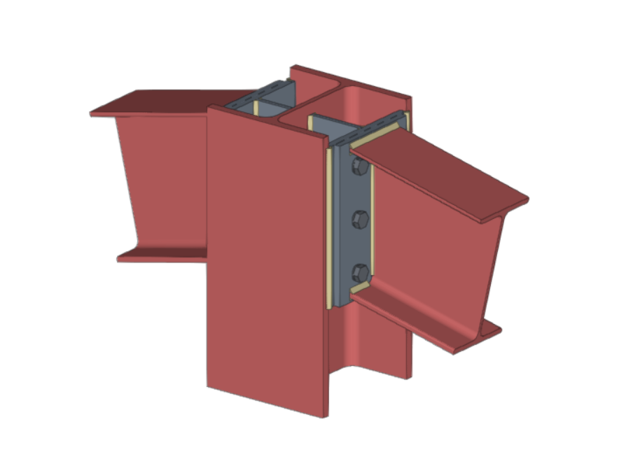

Both StruBIM Steel and CYPE Connect include a specific tool for modelling connections between structural steel elements. Both programs can access this tool via the "Connections" option.
The modelling and connection analysis panel has three tabs at the top: "Model", "Analysis" and "Sheets".
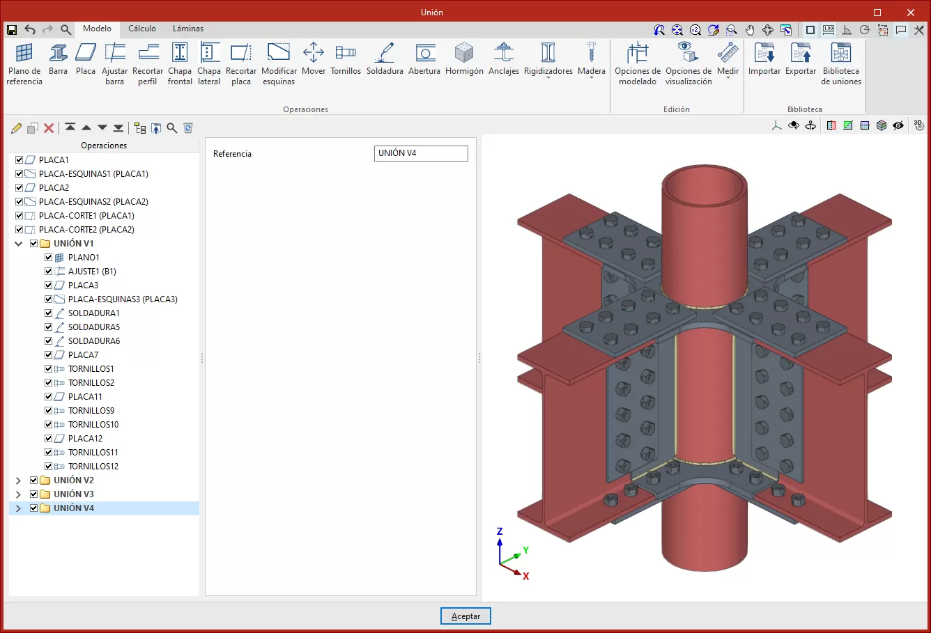
Modelling connections
Within the "Model" tab, users can enter a list of operations that are used sequentially to define the elements and geometry of the connection.
The entry order and the nomenclature used to identify each operation directly affect the way in which the connections are generated. During the modelling process, the program displays warnings about possible incompatibilities between modelled elements.
| More information: |
|---|
| Detailed examples of how each operation works can be found in the CYPE Connect Quickstart guide videos. |
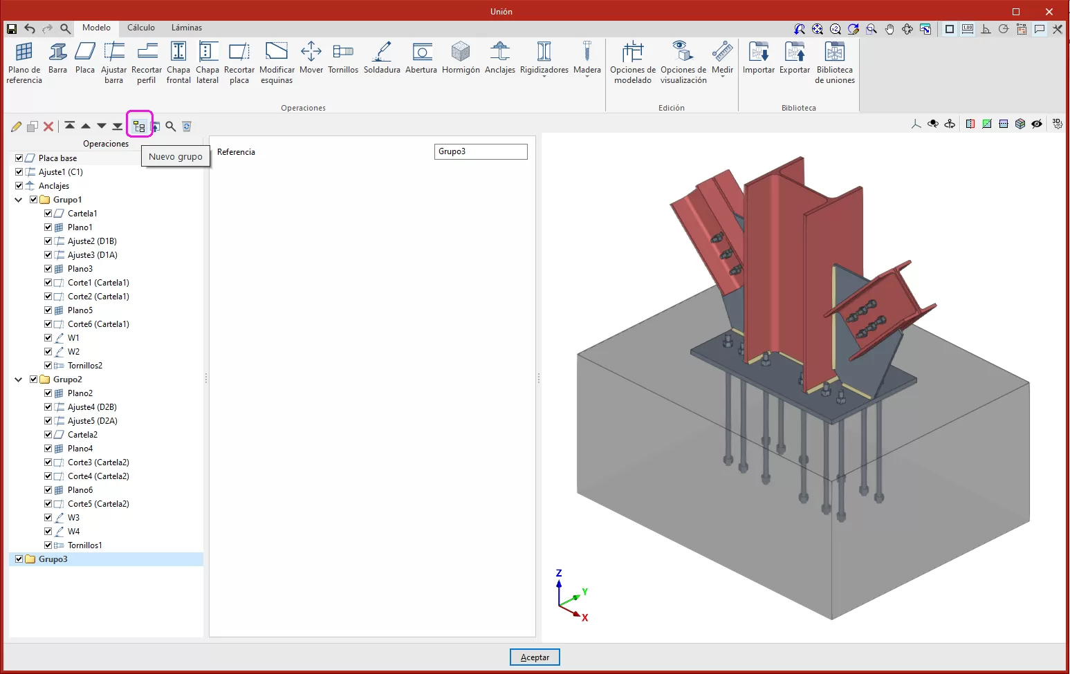
The connection editor is used to organise the list of operations by including groups of operations with an icon to identify each operation in the list.
It also has an option bar that includes several features.
- The "New group" option adds a new empty operation group. When a group is selected, new operations are added within this group. To insert or move an existing operation into or out of a group, use the tools to move up or down, depending on the position. Operations can also be dragged and dropped into or out of a group. This feature allows moves operations or groups of operations to another position, allowing an operation to be moved directly to the desired position without having to go through the intermediate positions one by one. Groups of operations can be expanded or collapsed, to either display or hide the operations they contain.
- A group of operations can be activated or deactivated by ticking the box on the left-hand side of the name for each group, which will affect all the operations included in the group.
- "Move up" moves the selected operation or group to the top of the list.
- "Move down" moves the selected operation or group to the end of the list.
- "Search" is used to search for operations by text.
- "Delete all the elements from the list" deletes all operations and groups of operations from the list.
- "Copy", with a group selected, is used to copy the group with all its operations.
- "Delete" is used to delete the group and all the operations it contains, or to delete the group and keep the operations ungrouped.
- "Export selected transactions to library", if you have a group selected, exports all the transactions contained in that group.
The main toolbar in this group allows the following operations to be carried out:
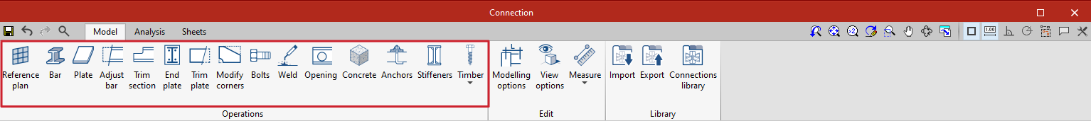
| Reference plan | Reference plans are used to make cuts in sections and plates, to make extension or reduction adjustments to these plans, or as a reference when adding plates. | |
 | Bar | This tool allows additional bars to be added to the connection in order to create drops, support elements, reinforcement for corbels, etc. |
 | Plate | This tool allows rectangular and polygonal plates to be generated. Polygonal plates can be defined from coordinates (tables can be copied and pasted directly from spreadsheets). |
 | Adjust bar | This operation allows a bar to be lengthened or shortened by fitting it to another bar, a reference plane or a plate. It also allows welds to be generated after this fitting. |
 | Trim section | This operation makes it possible to create a trim on the selected section according to the "x" and "y" magnitudes entered. The type of trim can also be defined: straight, with a chord radius or with drill. |
 | End plate | This operation allows one section to be joined to another by means of an end plate. Welds can be entered from the section to the plate and bolts can be entered between the plate and the section. |
| Lateral plate | Allows sections to be joined together by means of a plate welded to one section and bolted to the other. | |
 | Trim plate | This operation allows a plate to be trimmed from another element. The trim can be carried out from the face of a bar, from a previously defined reference plan or from another plate. |
| Modify corners | Allows users to define bevel, chamfer, notch, round and arc cuts at the corners of the plates. | |
| Move | Allows bars or plates to be moved using another element as a reference. | |
 | Bolts | This operation is used to enter bolts into the connection. Two elements to be bolted must be selected. If more than two are selected, the end elements of the connection must be indicated. |
 | Weld | This operation is used to enter welds between two elements. Both "Fillet", "Butt" and "Lap" welds can be created. |
| Round bar | Group of operations for round bars (Weld, Opening by intersection, Threaded connection and Connection plate). | |
 | Opening | This operation allows openings to be created in sections or plates. The openings can be circular or polygonal. |
 | Concrete | This operation allows concrete elements to be entered into the connection. Where necessary, anchors will be applied on top of them. |
 | Anchors | This operation is used after a plate has been entered and allows anchors to be added to the plate. Anchors are entered in the same way as the bolts. |
 | Stiffeners | This operation is used to enter the stiffeners via a wizard where their material, geometry, position and welds are defined. |
 | Timber | This operation is used to insert fasteners used in timber bars. It allows users to enter dowels, bolts and screws for timber. This feature is only available in CYPE Connect. |
The following link provides detailed information on the operations available in the connection editor, as well as examples of various connection modelling processes:
As well as the operations already mentioned, the program offers other additional tools to make the modelling of the connection easier:
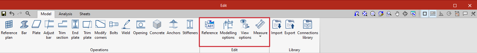
Reference: can be automatic or user-defined. The automatic reference is made up with the prefix defined in the sheet generation options. This feature is only available in StruBIM Steel.
Modelling options: allows users to edit the representation lengths and the analysis of the sections. For sections with curved segments, the program can analyse an optimal number of sides when discretising these segments or they can be chosen manually.
View options: allow the view of the elements to be configured so that they are displayed opaque or transparent, with or without reference axes, with or without labels and with or without the volume of the envelope.
Measure: allows measurements to be taken by selecting the elements of the connection.
Prequalified connections
Prequalified connections can be used in CYPE Connect and StruBIM Steel. To do this, within the "Operations" group of the "Model" tab in the editing window of each connection, the "Prequalified connections" operation is used, which allows a menu to be displayed with the different types available.

Definition and application
A prequalified connection is a structural connection whose geometry, construction detail and behaviour have been previously verified by testing and analysis, and which complies with the criteria set out in specific standards, especially in the field of earthquake-resistant construction.
Prequalified connections are applied and required in structures where the seismic-resisting system consists of moment frames (without bracing), particularly in the case of special frames (SMF) or intermediate frames (IMF), as defined in AISC 341.
Related regulations
In the program, the "Prequalified connections" operation only appears in projects that have one of the following steel codes selected:
- United States: AISC 360-22 (LRFD)
- Colombia: NSR-10
- Mexico: NTC-2023
Prequalified connection types available
The types of prequalified connections implemented are as follows:
- RBS (Reduced Beam Section)
- BEEP (Bolted Extended End Plate)
Includes types 4E (four-bolt unstiffened), 4ES (four-bolt stiffened) and 8ES (eight-bolt stiffened). - BFP (Bolted Flange Plate)
- WUF-W (Welded Unreinforced Flange-Welded Web)
The program can be used to define in detail the components of each prequalified connection in the operation's editing panel.
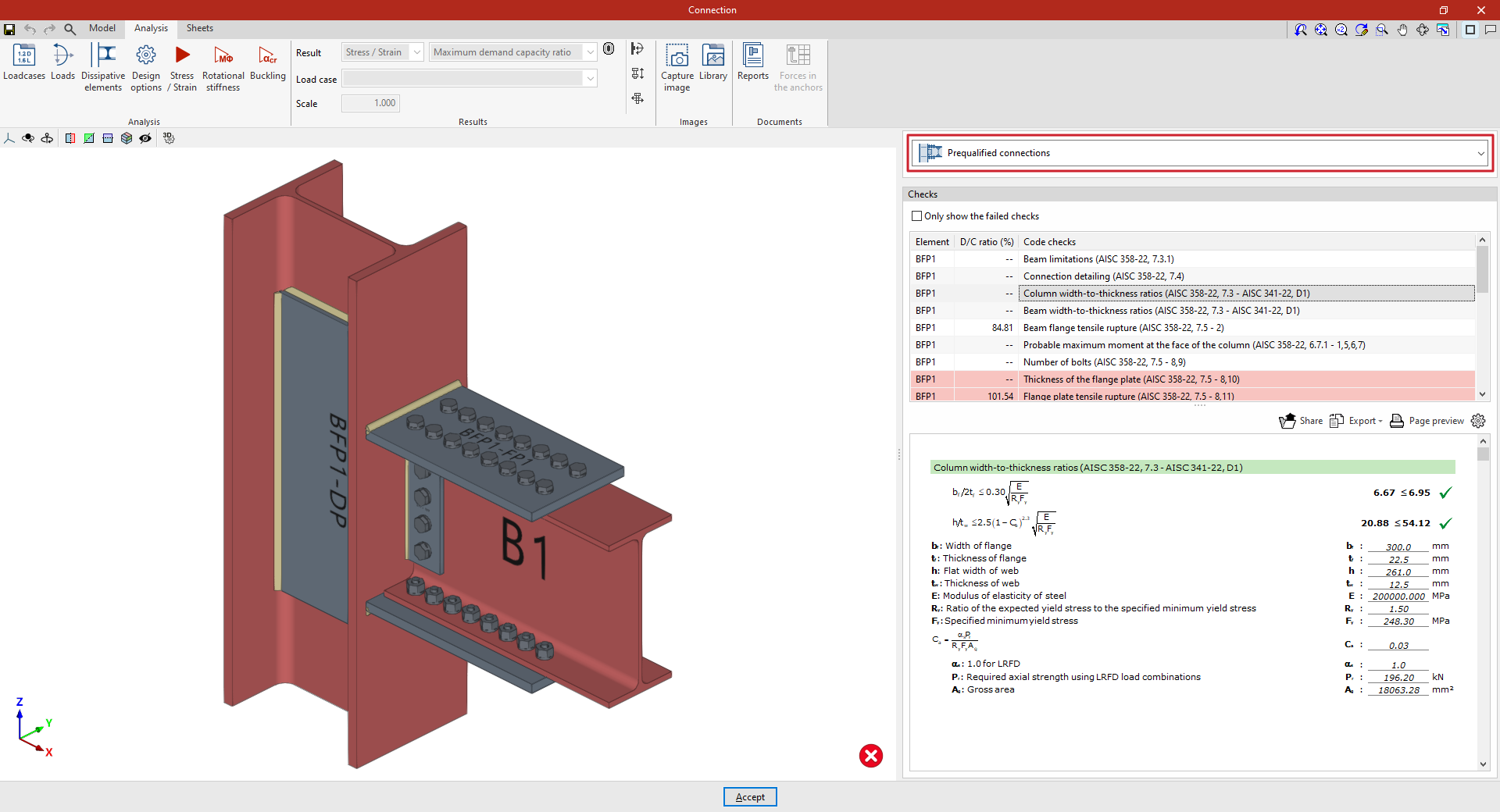
Checks on prequalified connections
In addition to the other checks carried out on the connection, the program carries out the specific checks defined in the AISC 341 and AISC 358 standards for prequalified connections.
These checks can be displayed on screen by selecting the "Prequalified connections" option, available in the corresponding drop-down in the "Analysis" tab of the connection editing window.
| Note: |
|---|
| Other operations can be defined at the same node where a prequalified connection has been inserted. This way, a different type of seismic-resisting system could be defined in each direction of the structure. In the direction where no pre-qualified connections are applied, the program will perform the usual checks after the finite element design. However, the prequalified connection check will not consider the effects of additional operations, displaying a warning in this case. |
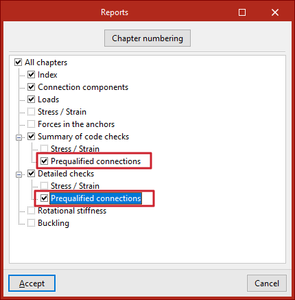
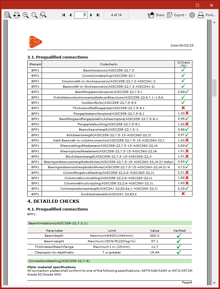
Prequalified connection check reports
The documents provided by the program include summarised and detailed reports of the checks carried out on the defined prequalified connections.
To obtain this, the corresponding sections of the report must be activated.
Connections library
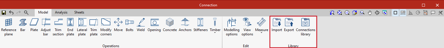
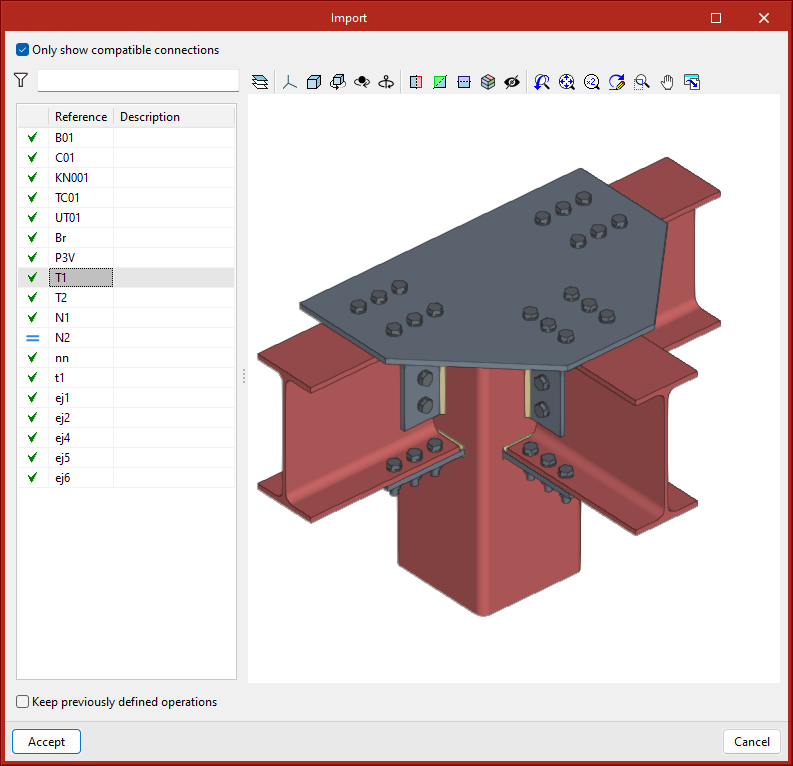
The connections library allows connections to be saved and applied to other nodes in the same job or other jobs. This library is common to CYPE Connect and StruBIM Steel. The “Import”, “Export” and “Connections library” options can be accessed from the connection editing panel.
- Import
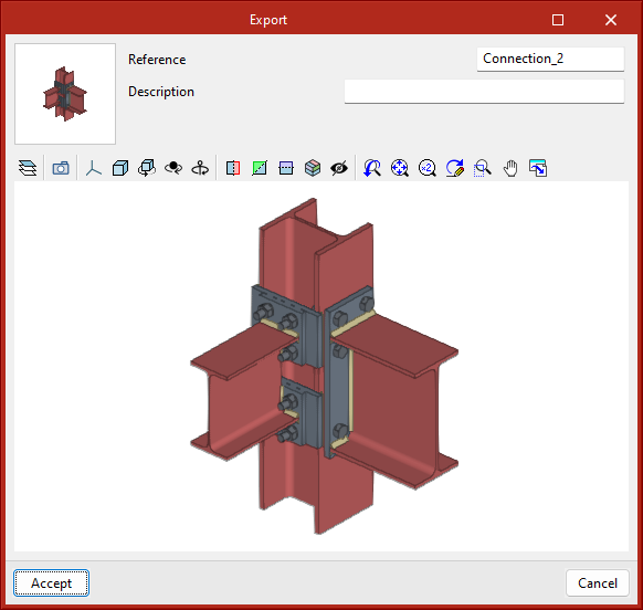
Joints between structural elements modelled in StruBIM Steel can be saved in a local library and reused in other projects. This library is compatible with CYPE Connect. - Export
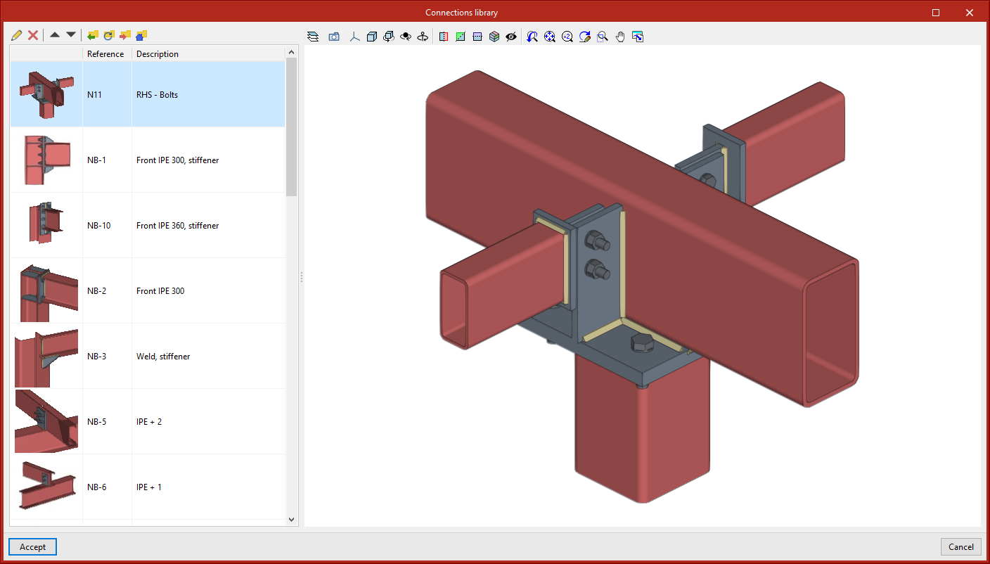
This tool allows a connection to be saved in the job's connection library with a reference, description and thumbnail image for identification. The connections exported to the connections library also save the sheets that have been defined, so that the work invested in creating the detailing sheet of the connection can be used for similar connections when applying a connection available in the library. - Connections library
The connection library includes a thumbnail view of the connection, a reference and a description. A 3D view is also displayed where the connection can be moved, shifted and orbited.
The top part shows the options related to the management of this library:
- Import elements saved on disk into the job
- Update the elements used in the project
- Export the element to a file
- Select a file with initial values for the creation of a new job
Analysis and code checking of connections
Once the connection has been modelled, the analysis and checking can be carried out. The "Analysis" tab has the following options for this purpose:
Generate from the BIM model
This option will be available when the job has been created from a BIM model with forces. The load cases and loads of the sections involved in the connection can be generated.
To do this, the load combinations to be read can be filtered. Not all load combinations have significant values, so it may be advisable to filter the number of combinations to be imported. By default, a filter is shown for each of the 6 forces. The combinations in which the force exceeds the maximum value by a certain percentage, both positive and negative, will be read for each force. Furthermore, a minimum value can be set to determine whether the combinations should be read.
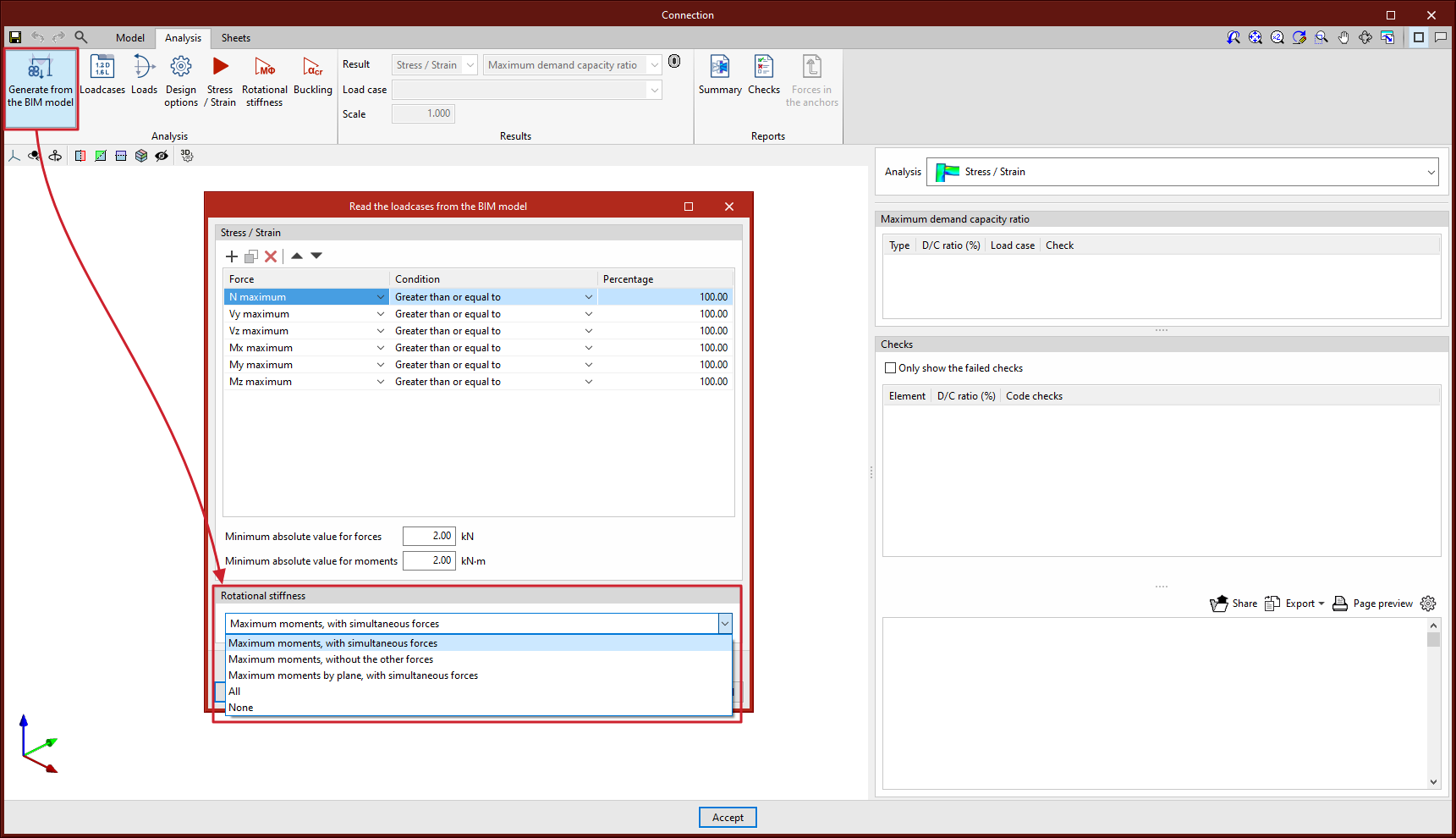
With this option, loads can also be imported for the rotational stiffness analysis. In addition to the loads, the elastic lengths of the bars of the structural model are also imported; these lengths are necessary for the correct classification of the connection. There are five options for importing load cases according to forces:
- Maximum moments, with simultaneous forces
Imports the load cases with the largest moments "My" or "Mz", with a positive or negative sign, in addition to the other simultaneous forces. - Maximum moments, without the other forces
Only imports the "My" and "Mz" values from load cases with maximum moments. - Maximum moments by plane, with simultaneous forces
Imports load cases with maximum moments and their simultaneous forces per plane i.e. creates load cases with forces per plane (XY and XZ). - All
Imports all load cases. - None
No load cases are imported.
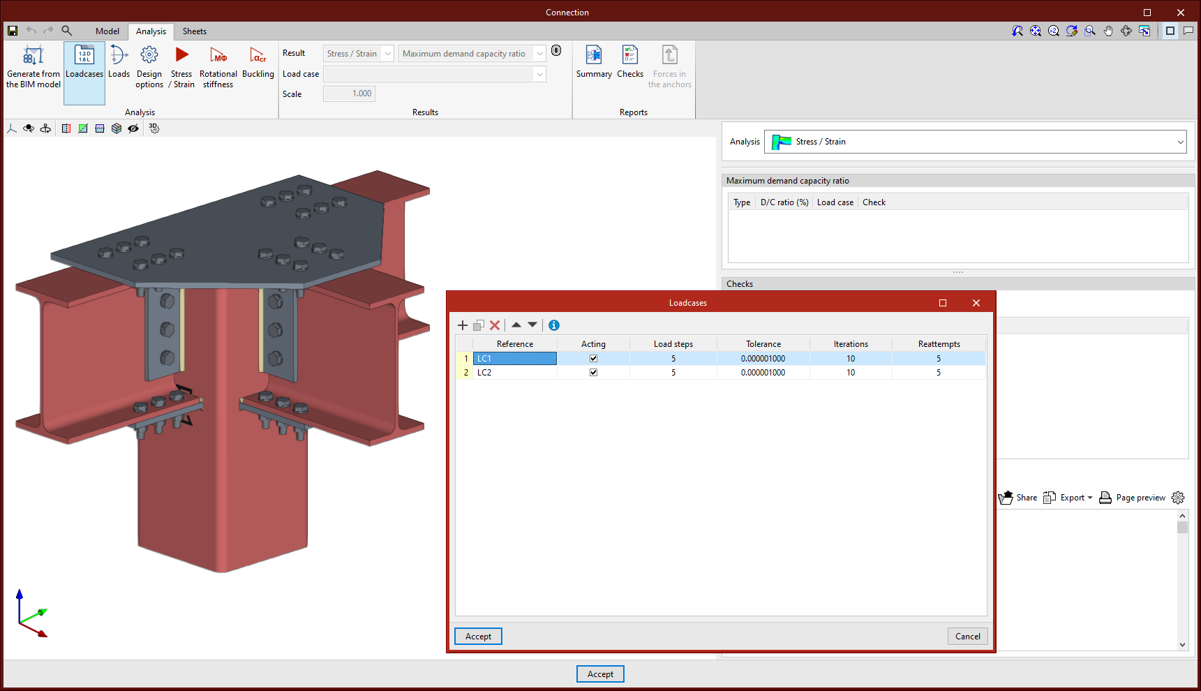
Loadcases
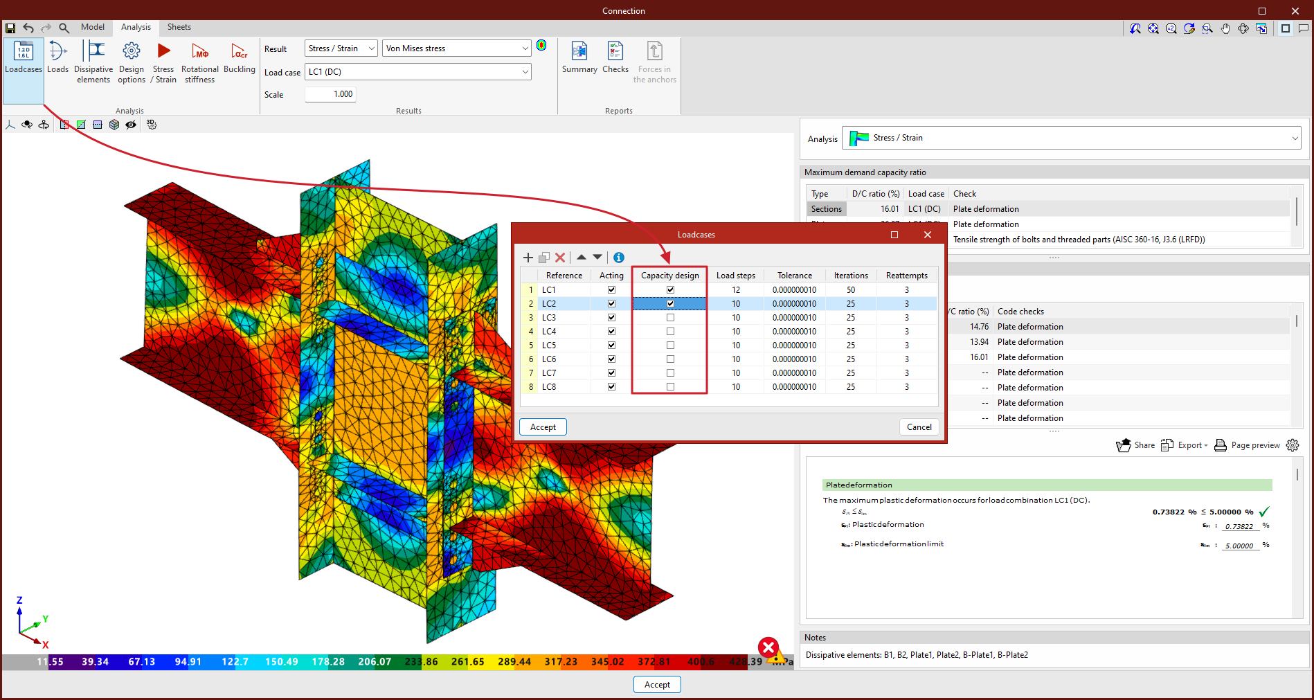
This option can be used for defining the load cases to be considered in the connection analysis. These load cases can be generated from the BIM model or configured manually by the user. The following parameters are defined for each load case:
- Number of load steps.
- Allowable tolerance to consider the convergence has been reached.
- Maximum number of iterations in each load step.
- Maximum number of reattempts.
Loads
This tool opens the "Loads" dialogue box, where the loads acting on each section for each load case are defined.
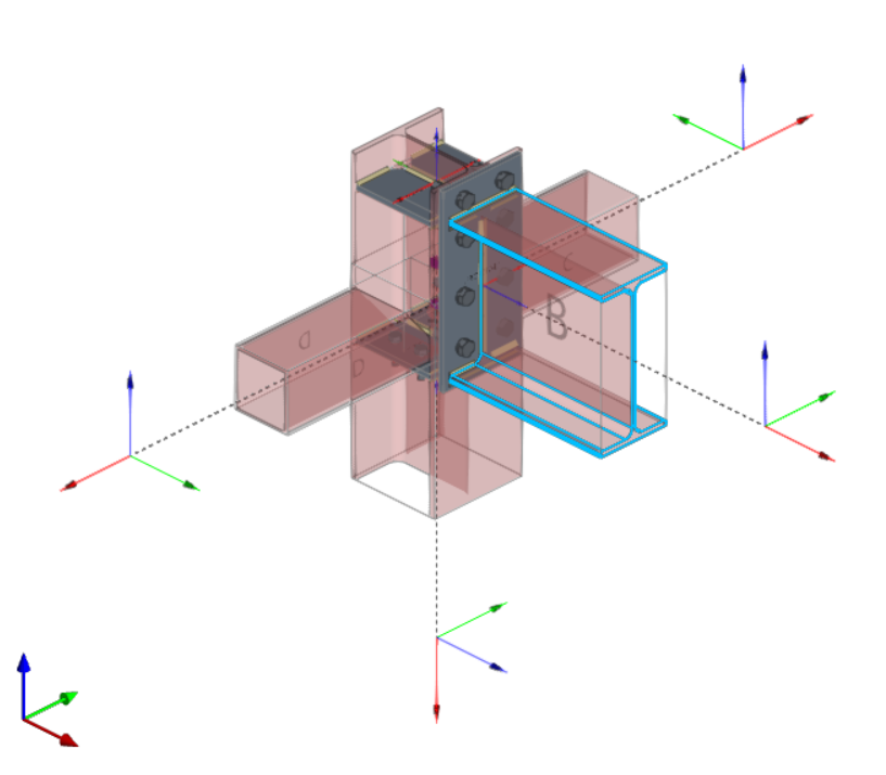
In the connection analysis model, one of the bars is set as the load-bearing element, unless a baseplate has been defined. The remaining bars are connected to this element, where the loads are applied.
Each non-load-bearing bar includes the "Design model" option, which selects different load and restraint configurations, best suited to various structural situations. Users can choose from the following options:
- N - Vy - Vz - Mx - My - Mz
This is the default model. The end of the bar has no external links, so that the six forces can be defined. - N - Vy - Mz
This model defines loads in the XY drawing. The end of the bar is constrained for displacement in the z-axis and rotation in the y-axis. - N - Vz - My
This model defines loads in the XZ-plane. The bar end is constrained for displacement in the y-axis and rotation in the z-axis. - N - Vy - Vz
In this model, the end of the bar is constrained for rotation and does not allow moments to be entered.
In the central part of the dialogue box, there are two tabs for defining load tables, per load case. Tables can be copied and pasted directly from a spreadsheet.
In the "Stress / Strain, Buckling" tab, in addition to the loads, it is possible to define the position of the force application point for each section. This distance will also be read in the BIM model, provided that the structure has been designed considering the finite dimension of the nodes.
The bars from which the rotational stiffness of the connection is to be analysed can also be selected. The "Rotational stiffness" tab asks for a report of loads, the lengths of the elastic bar in the structural model (used to establish the limit stiffnesses of rigid or pinned connections) and the kb factor.
The "Edit forces" tool, common to both tabs, is used to define the forces applied to each bar according to its mechanical properties. This feature makes it easier to design connections with a higher resistance than that of the connected bars, a common requirement in different seismic design standards.
To improve the visualisation, in the 3D view of the dialogue box, the loads applied to each bar in the connection are graphically represented according to the selected load case.


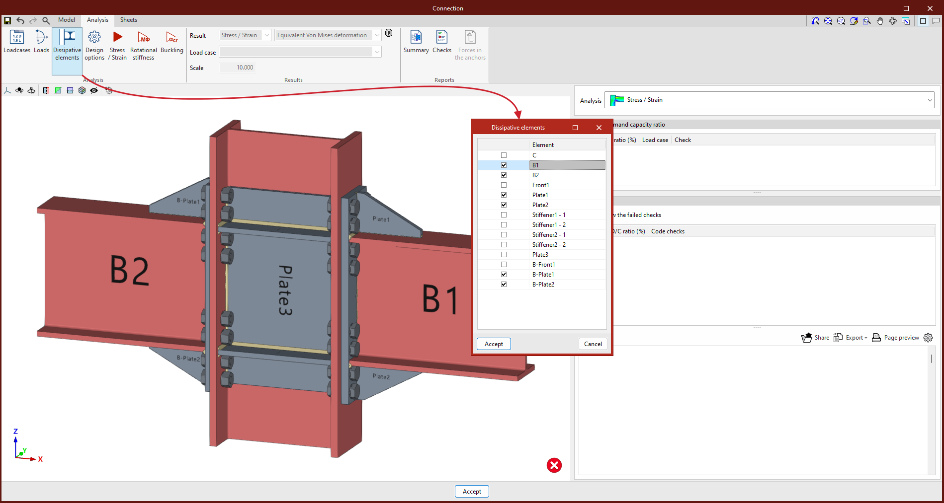
Dissipation elements
The analysis of connections with dissipative elements can be carried out. These tools can be used to design connections for earthquake-resistant structures in which energy dissipation is foreseen through the formation of plastic hinges, either in one of the elements of the connection or in the bars linked to it.
In the "Analysis" tab, a tool has been added to select the dissipative elements, offering users the option to choose between sections and plates. The material properties of the dissipative elements are transformed in the load cases marked as "Capacity design", considering the effects of material overstrength.
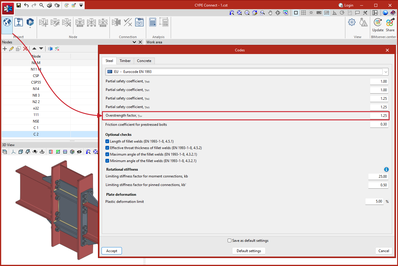
For Eurocodes and similar standards, the program will request the overstrength coefficient of the material, 𝛾ov, which amplifies both the yield strength and the ultimate strength of the dissipative elements. For American standards such as AISC360, NSR10, NTC-2023, among others, and other similar standards, the program will include in the material library the specific overstrength factors for each type of steel, Ry and Rt.
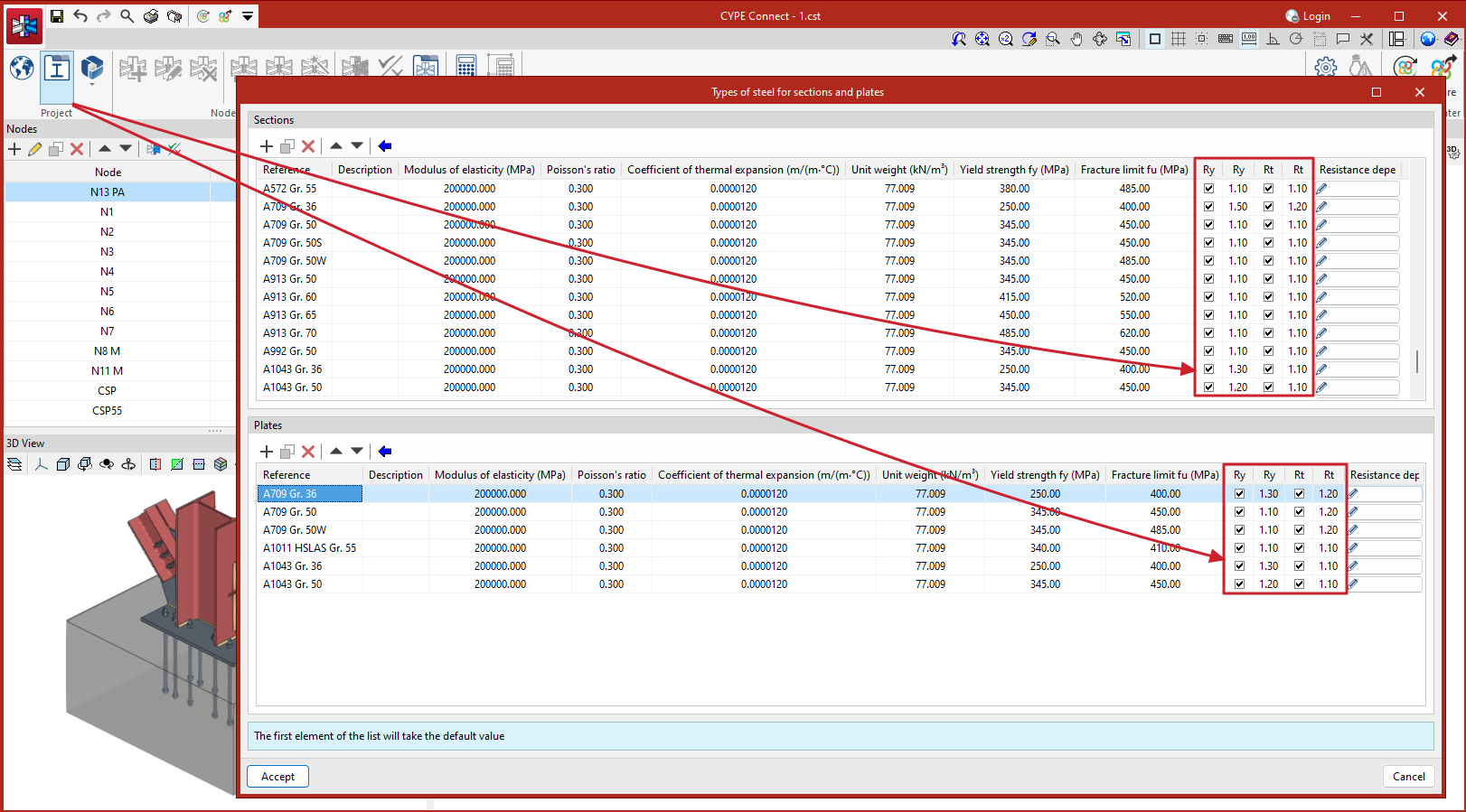
To analyse the connection for the over-resistance in dissipative elements, it is necessary to select not only the dissipative elements but also the "Capacity design" types of load cases in the list of load cases.
This new implementation allows users to design the connections so that the capacity of the connection is larger than that of the dissipative element while considering the over-resistance. In these cases, dissipative elements will experience large plastic deformations, which makes it difficult to converge the model, therefore, another relevant parameter in dissipative elements is the slope of the plastic span.
As detailed in the calculations manual, the constitutive law for plates and sections follows a bilinear model, where the slope of the plastic span is tan-¹(E/1000). For dissipative elements, in addition to incorporating the over-resistance coefficient as a multiplier of the yield stress, the slope of the plastic span is adjusted. In these elements, for a deformation of 5%, the stress will reach the elastic limit of the material, amplified by the over-resistance coefficient (𝛾ov or Ry, depending on the applied standard) and by the resistance reserve coefficient due to strain hardening, which is equal to 1.1. This slope, greater than tan-¹(E/1000), contributes to improve the convergence of the analysis.
Design options
Here, users can define the following:
- The maximum discretisation size of elements.
- The length to calculate the average weld stresses.
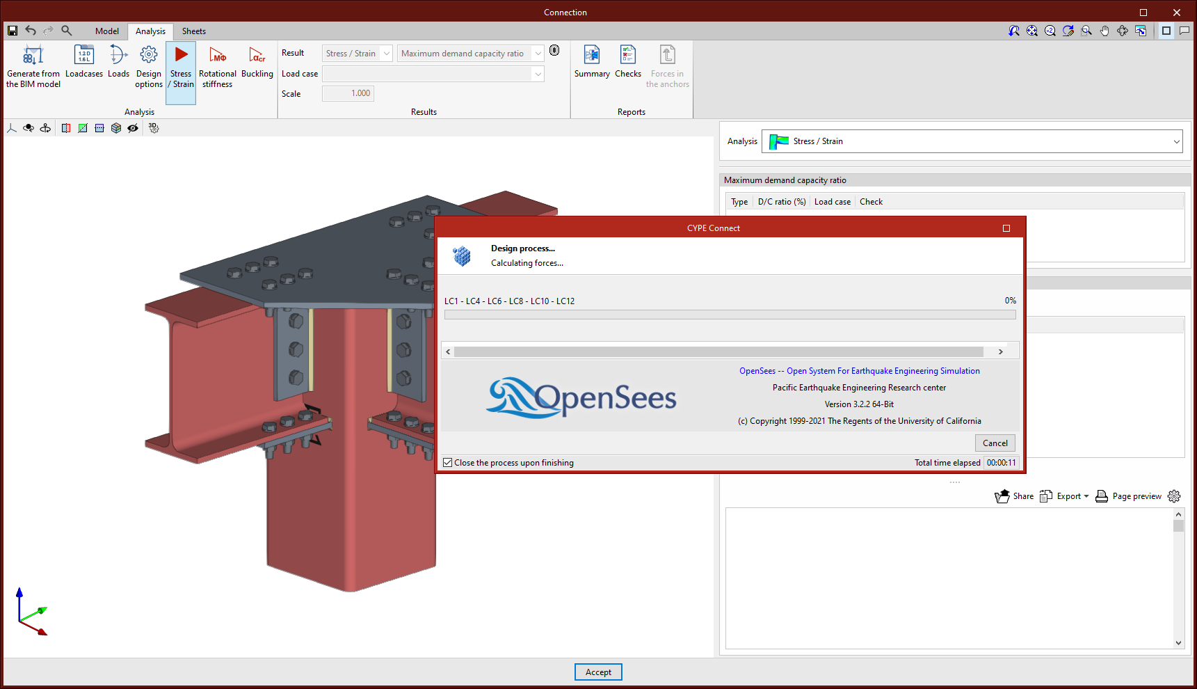
- The multi-process analysis method of the OpenSees© analysis engine.

| More information: |
|---|
| More information on analysis considerations can be found in the CYPE Connect calculation report. |
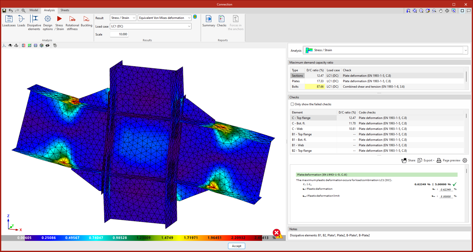
Stress / Strain
Clicking on the "Stress / Strain" button starts the stress analysis and checks. The first time the analysis is run, the implemented version of OpenSees© will be installed automatically.
Rotational stiffness
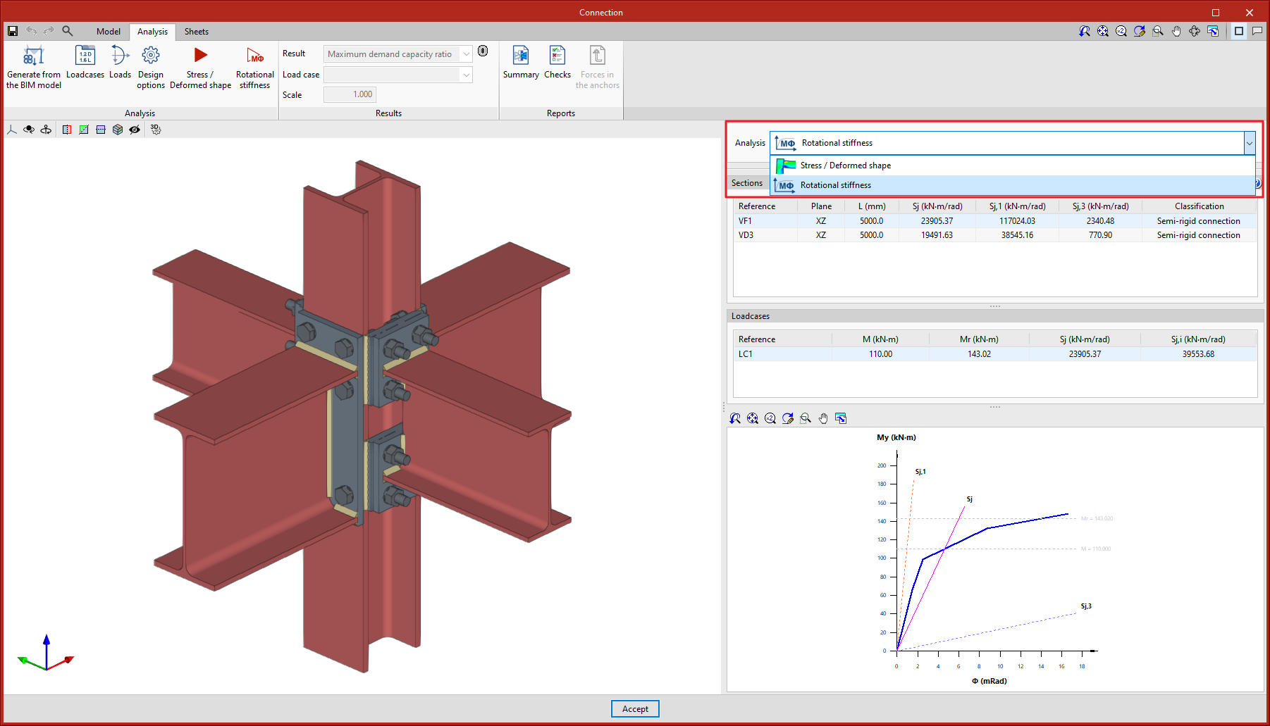
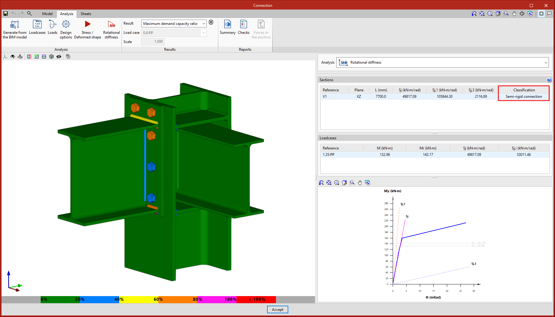
Clicking on the "Rotational stiffness" button will start the force analysis and checks. This analysis option allows users to obtain the resistant moment, the initial stiffness, the secant stiffness and the classification of the connection (rigid, semi-rigid or pinned) of the steel sections.
The results are displayed on the right-hand side of the "Analysis" tab. In the drop-down menu at the top, you can select the type of results to be displayed, "Stress/Strain" or "Rotational stiffness". When choosing "Rotational stiffness", the program displays two tables and the "Moment - Rotation" graph.
To obtain the "Moment - Rotation" graph, the program runs an iterative process analysing the rotation in different load steps. The resistant moment is obtained when any element of the connection (plates, sections, welds or bolts) does not comply, i.e. when its demand capacity ratio is greater than 100%.
The first table shows all bars analysed with the secant stiffness and the classification of the connection in each plan. The second table displays the analysed load cases for the selected bar. Each load case indicates the acting moment, the resisting moment, the secant stiffness and the initial stiffness.
The graph shows the curves for "Moment - Rotation", "Acting moment of the selected load case", "Resistant moment", "Ultimate stiffness for rigid connections (Sj,1)" and "Ultimate stiffness for pinned connections (Sj,2)".
Classifying the connection
To classify the connection as rigid, semi-rigid or pinned, the limit stiffnesses of rigid and pinned connections must first be established. Depending on the selected steel codes, the initial stiffness or the secant stiffness will be compared with these limits.
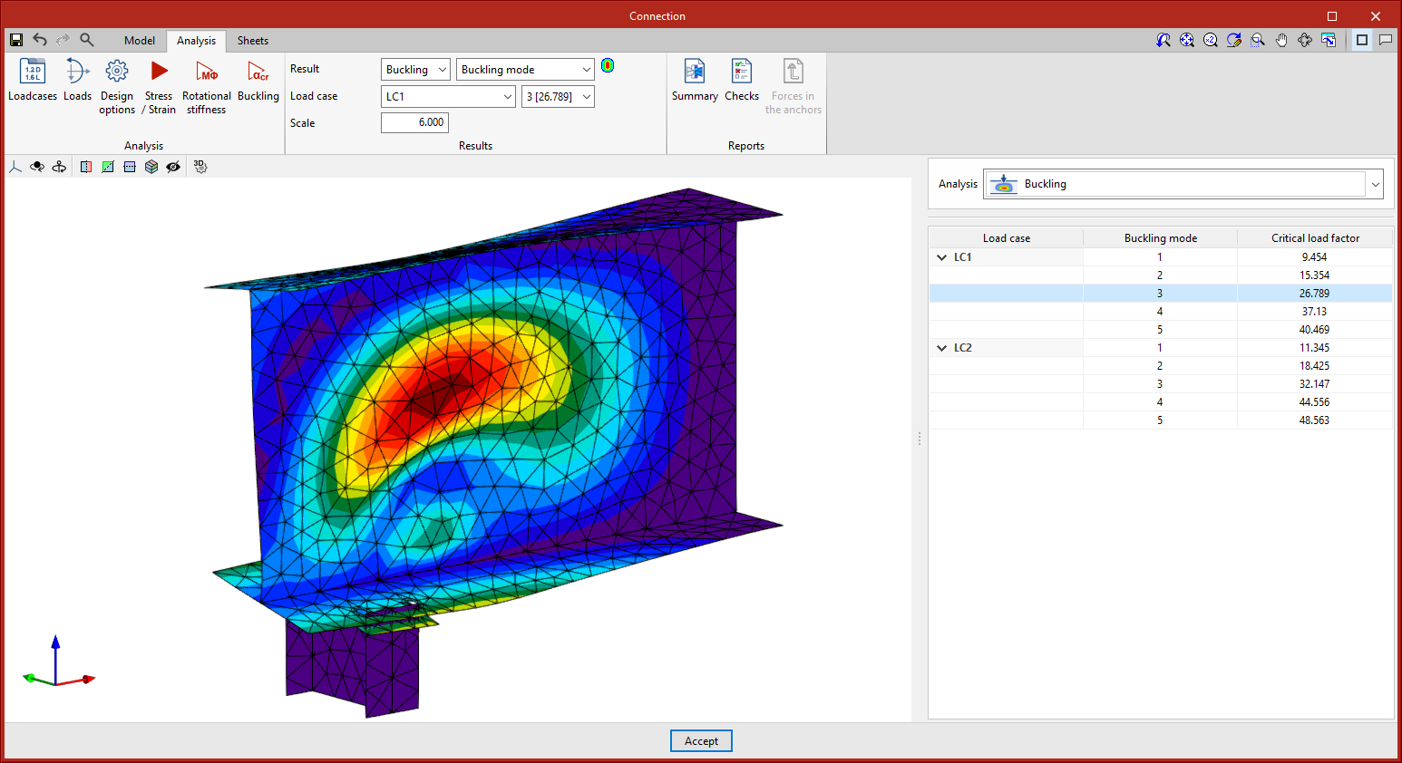
Buckling
Clicking on the "Buckling" button will start the analysis. The local buckling of a connection component occurs due to compression forces and mostly depends on the stiffness of the component and the distribution of the applied loads. The buckling analysis helps to detect unstable connection design configurations under the load of a particular load case.
There are several ways to evaluate the buckling phenomenon using Finite Elements. The one implemented in the connection analysis is the "Linear buckling analysis" which allows users to obtain the critical load factors of the different local buckling modes of the connection for a given load case.
Once the analysis is completed, we obtain the critical load factors for each of the buckling modes as well as their deformed shape. The smaller the first critical load factor, the closer we are to an unstable connection configuration.
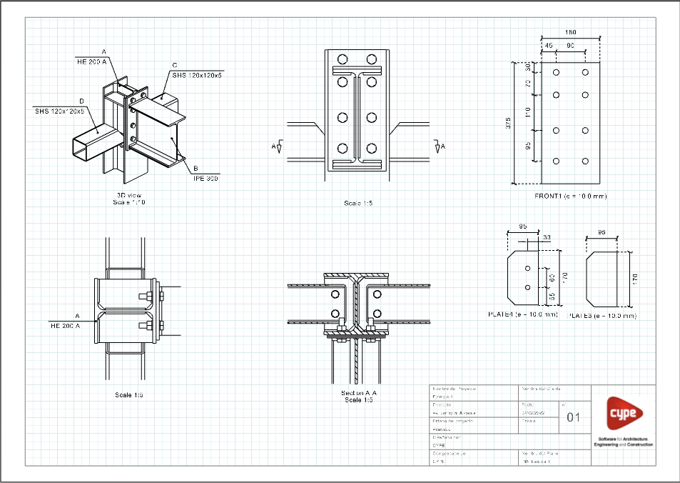
Graphical information for connections
In the "Sheets" tab, there are several tools that allow detailed sheets of the connections to be obtained from the data previously entered in the modelling phase.
All the features found in "Edit sheets" are also available for the layout of the sheets in the connection.
From this window, users can enter views, dimensions, label elements, insert external files, create user symbols and generate tables, among many other options.
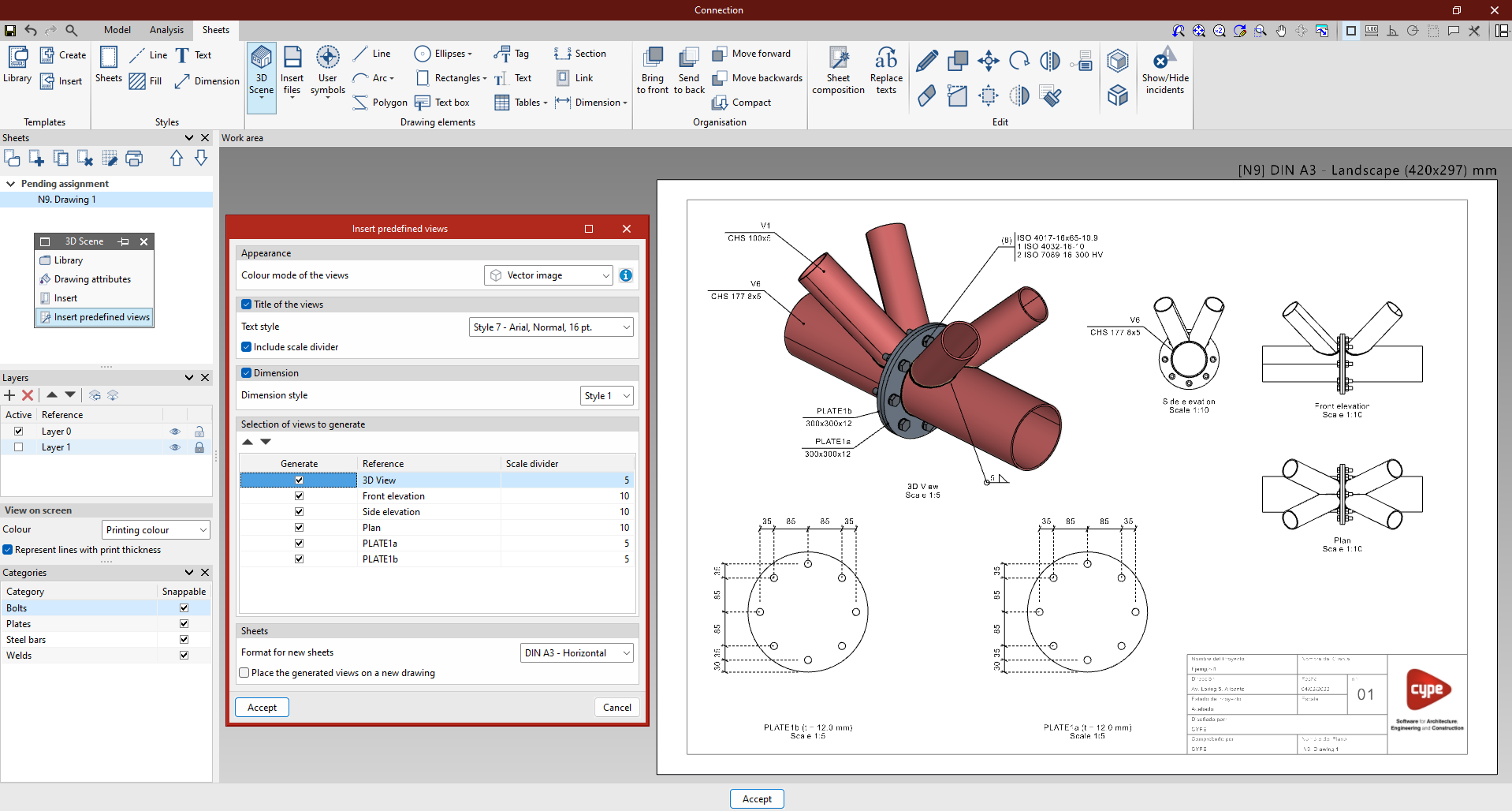
In the "Drawing elements" group, select the "3D scenes" option and click on "Insert predefined views".
In the pop-up panel, the selected views can be configured. Users can choose the colour mode of the views, whether they are to be dimensioned and referenced, as well as their respective styles. The desired scale can also be configured.
Linking to the connection model
The content of the sheets is linked to the model of the connection, i.e. the scenes and views that have been defined as well as the element tags that have been entered will be automatically updated if changes are made to the connection model. In case the connection is exported to the "Connection library", the sheets will also be exported and can be reused in future projects.
Accessories
A tool is included in StruBIM Steel for entering elements at the intermediate points of sections. This tool can be accessed via the "Accessory" option.
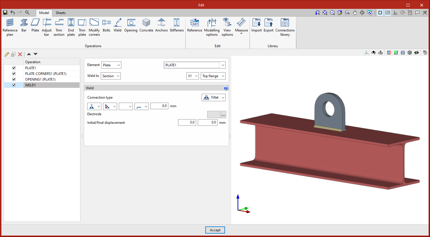
The dialogue box for working with accessories is similar to the CYPE Connect connection editor. The purpose of this tool is to allow users to enter holes, openings, reinforcements, lifting lugs, etc. with the advantages offered by the connection editor. The accessories, like the connections, can also be grouped and saved in a library.
The symbol representing the accessories is a green pyramid, as opposed to the purple pyramid used for the connections.
This feature is only available on StruBIM Steel.
Options for grouping and creating nodes
A group of nodes will be assigned the same connection. The connection assigned to a group of nodes will read from the BIM project the bar forces of all the nodes in that group. The combination filter obtained from "Generate from BIM model" is carried out by adding up the combinations of all the nodes.
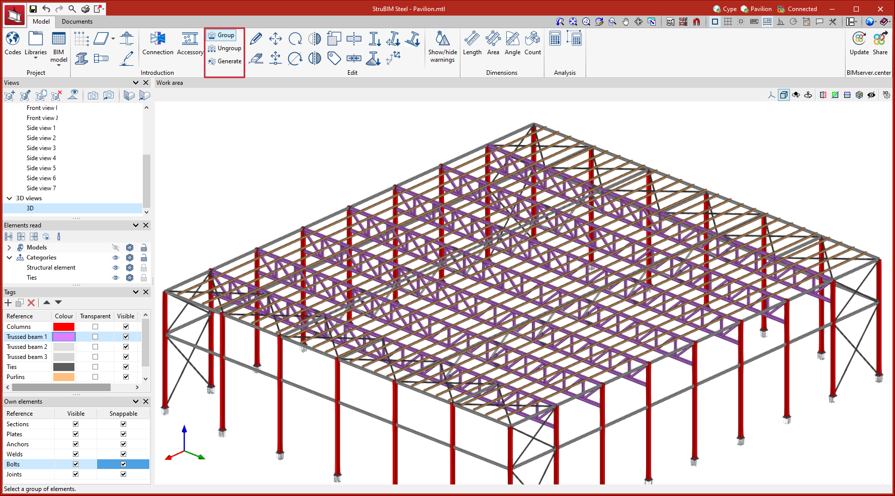
The options available to generate these groups are as follows:
- Group
Allows matching nodes to be grouped together. When a node is selected, all those that match are highlighted in yellow. - Ungroup
Allows previously grouped nodes to be ungrouped. - Generate
Generates nodes and automatically groups matching nodes.
Editing tools
Within the "Model" tab, in the "Edit" group of the main toolbar, the main tools for editing the model can be found. Some of these tools are common to other CYPE programs.

 | Edit | Selects a model element and edits its parametric properties. |
 | Delete | Deletes a previously entered element. |
 | Move a group of elements | Moves a group of elements. |
 | Move | Moves a single element. |
 | Rotate | Rotates a group of elements. |
| Rotate about an axis | Rotates a group of elements around an axis defined by two points. | |
| Symmetry (move) | Moves a selection of elements with symmetry with respect to a vertical plane defined by two points. | |
| Symmetry (copy) | Copies a selection of elements with symmetry with respect to a vertical plane defined by two points. | |
| Copy | Creates a copy of an element. | |
 | Assign tags | Assigns the tags of a given element to another element. |
 | Divide | Divides a bar into two parts at a given point. |
 | Join | Joins two bars. |
 | Assign section | Assigns the cross-sectional properties of a particular bar to another bar. |
| Assign material | Allows the material type to be assigned to a selection of sections. | |
| Assign insertion point | Allows users to assign the levelling point, rotation angle and Y and Z displacements in local axes to a selection of sections. | |
| Invert the direction of the X axis | Inverts the X axis direction of a selection of sections. | |
| Align section with the plane | Allows a selection of sections to be aligned with a plane. | |
| Flip | Allows sections to be flipped around their longitudinal axis. | |
| Level section face with plane | Allows sections to be moved until one of their faces is aligned with the face of another element. |
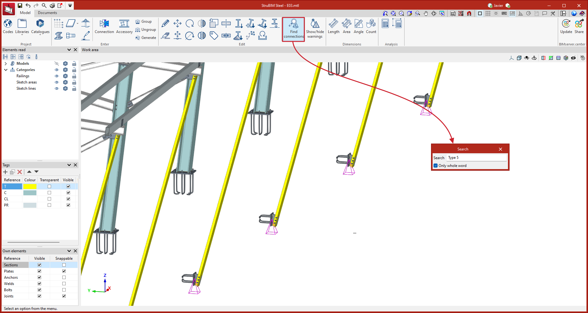
Connection search
StruBIM Steel can be used to search for connections. To do this, when running the tool, a panel is displayed where the reference of the connection to be located can be entered. All connections that fully or partially match the text entered will be highlighted, depending on whether or not the "Only whole word" option is enabled.
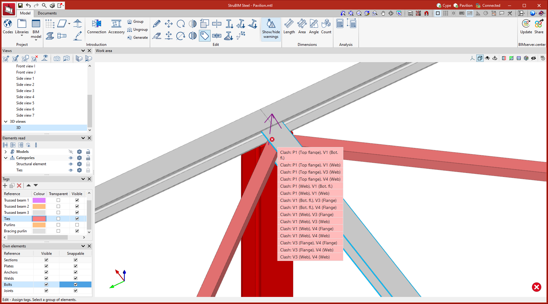
Warnings
The program analyses the structure for clashes between two or more modelled elements. Using the "Show/hide warnings" option, warnings can be activated to indicate where these clashes occur, and which elements are involved.
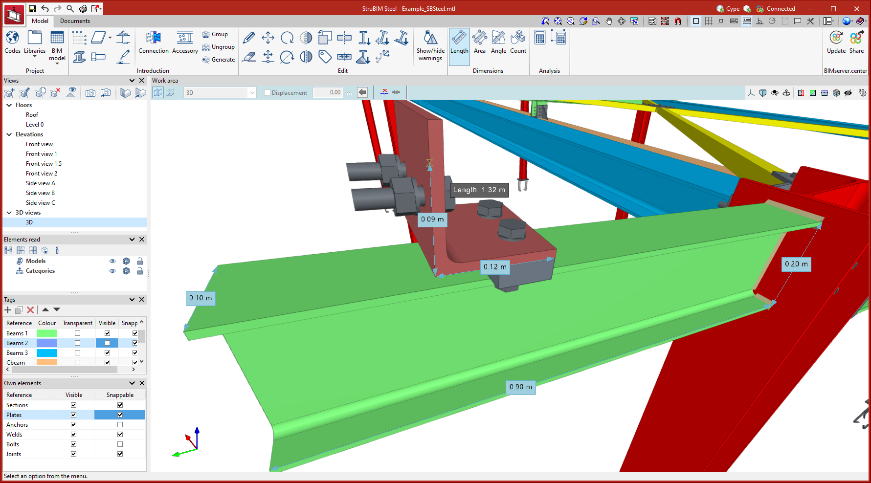
Measuring tools
Within the "Model" tab, in the "Dimensions" group of the main toolbar, you will find the tools for making measurements in the work area.

The options available for measuring are the following:
- Length
Allows the distance between points inserted in the work area to be measured. Several segments can be entered and the application will calculate the sum of the lengths of each one. - Area
Allows the area of a polygon defined by points inserted in the work area to be measured. Several polygons can be entered and the application will calculate the sum of the areas of each one. - Angle
Allows the angle formed by three points inserted in the work area to be measured. Several angles can be defined and the application will calculate the sum of them. - Count
Allows the number of selected 3D model objects to be counted.
"Analysis" group in the main toolbar
Connections modelled in StruBIM Steel or imported from the CYPE Connect compatible library can also be analysed according to the previously selected code criteria (see more information in the "Modelling, analysis and graphical information of connections" section) as well as being modelled with all the necessary fabrication information. For this to be possible, the license used must contain CYPE Connect and the OpenSees module as well as StruBIM Steel.

If these conditions are met, via the tools in the "Analysis" group of the main toolbar, users can carry out the following:
Analyse all the connections
The program will start an analysis of all the modelled connections of the structure and will issue a final report with the analysis results.
Analyse the selected connections
After selecting one or more connections, the program will start the analysis process of the selected connections. This process is ideal for quickly checking connections that have been modified.
| More information: |
|---|
| Further information on CYPE Connect and OpenSees©, and the modules required to carry out the analysis of the connections, can be found on the CYPE Connect page. |
Numbering parts and assemblies
In the “Documents” tab, in the “Numbering” group of the main toolbar, the main tools for the automatic and manual numbering of parts and assemblies can be found.

 | Parts | Numbers all parts of the model. |
 | Part selection | Numbers all selected parts via a selection window. |
| Search for assemblies | Allows users to search for assemblies. The elements corresponding to the search are marked in the 3D view. | |
 | Assemblies | Number all assemblies in the model. |
 | Assembly selection | Numbers all selected assemblies via a selection window. |
 | Assign | Creates assemblies manually. |
 | Ungroup | Ungroups sets that have been manually grouped. |
 | Edit | Edits the numbering of an assembly or part. |
 | Assign main part | Assigns a main part to an assembly. |
| Search for parts | Allows users to search for assemblies. The elements corresponding to the search are marked in the 3D view. |
Detailing sheets
In CYPE Connect ("Fabrication" mode), within the "Documents" tab, in the "Sheets" group of the main toolbar, the features required to generate the graphical information of the structure can be found. Using these tools, it is possible to create sheets of elements and parts (sections and plates), assembly sheets, connection sheets and sheets with the general views of the model. From the “Sheets” menu, you can access the “Generation options”, “Parts”, “Assemblies”, “Joints”, “Model views”, “Composition” and “List” tools.
These tools are included in the "Structural steel detailing drawings" module, and their use requires the user license to have the corresponding code for this module.

Generation options
The generation options are arranged in a dialogue box with four tabs: "Parts", "Assemblies", "Joints" and "Model views". They all have common and specific options.
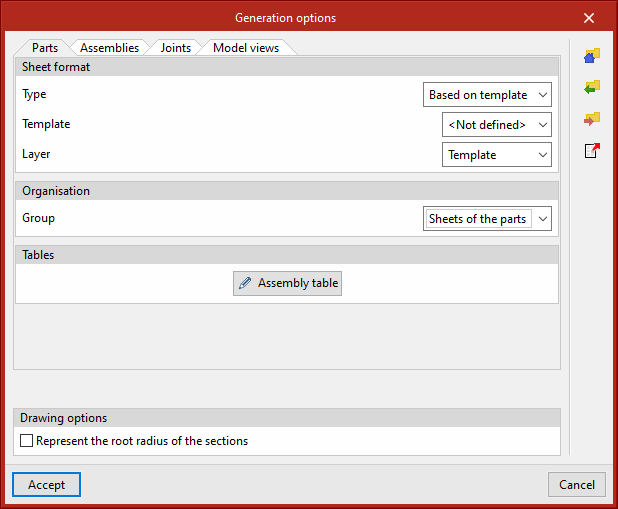

Sheet format (included in all four tabs)
Select the format of the new sheets. In "Type", "Empty" can be selected together with the sheet format or "Based on template" together with the selection of a previously created template and its corresponding layer. The template has a sheet format associated with it.
Organisation (included in the four tabs)
Select the group of sheets in which the newly created sheets will be generated.
Tables ("Parts" and "Assemblies" tabs)
Select the text formatting of the predefined tables in the tabs.
Drawing options (included in all four tabs)
In this section, the option for displaying the chord radius of the sections can be found. This option is deactivated by default.
Tags of the “Assemblies” and “Model views” tabs
Select the information that will appear on the automatic tags in the main part of the assembly.
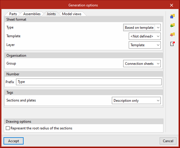
Number (“Joints” tab)
Define a prefix for numbering the joints.
Tags in the “Joints” tab
Select the information that will appear on the automatic tags of sections and plates.
All generation option settings can be saved in the user library. User libraries can be managed via the options buttons on the right-hand side of the “Generation options” dialogue box.
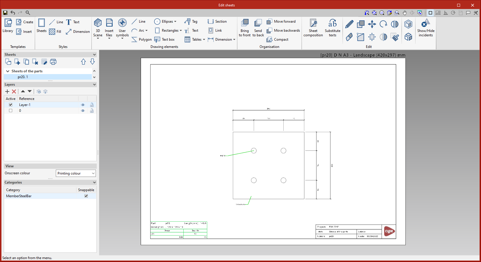
Parts
This tool provides access to the drawing and editing panel of the sheets of the parts of the selected element. In the sheets of the parts, only one element (section or plate) is shown and its geometry is graphically documented. In these sheets, the predefined table of uses of the part in assemblies can be entered.
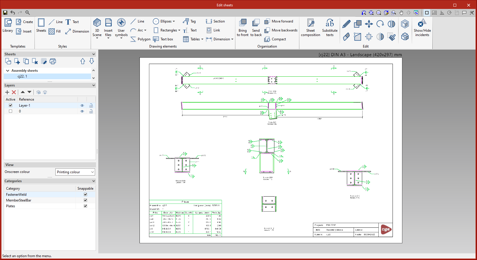
Assemblies
This tool provides access to the drawing and editing panel of the assembly sheets of the selected element. The assembly sheets show all the elements (sections, plates, welds, bolts or anchors) that are part of the assembly being assembled in the workshop. In these sheets, the predefined table of the parts of the assembly can be entered.
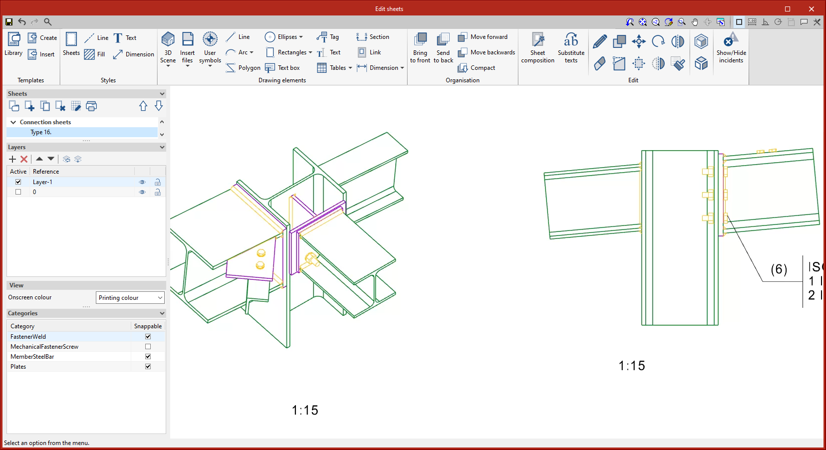
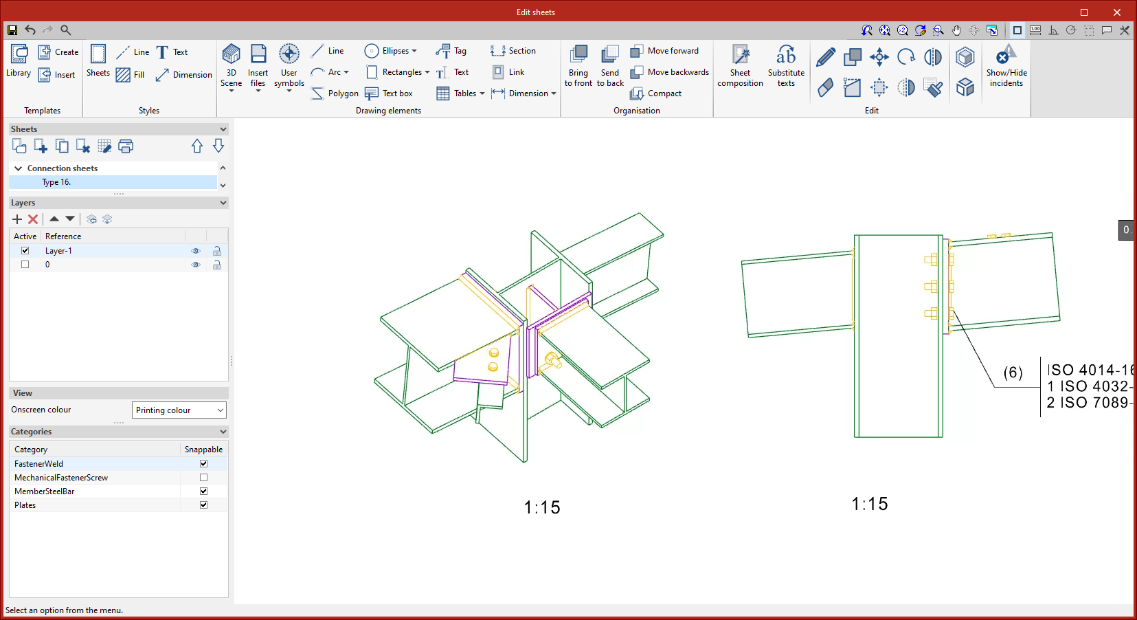
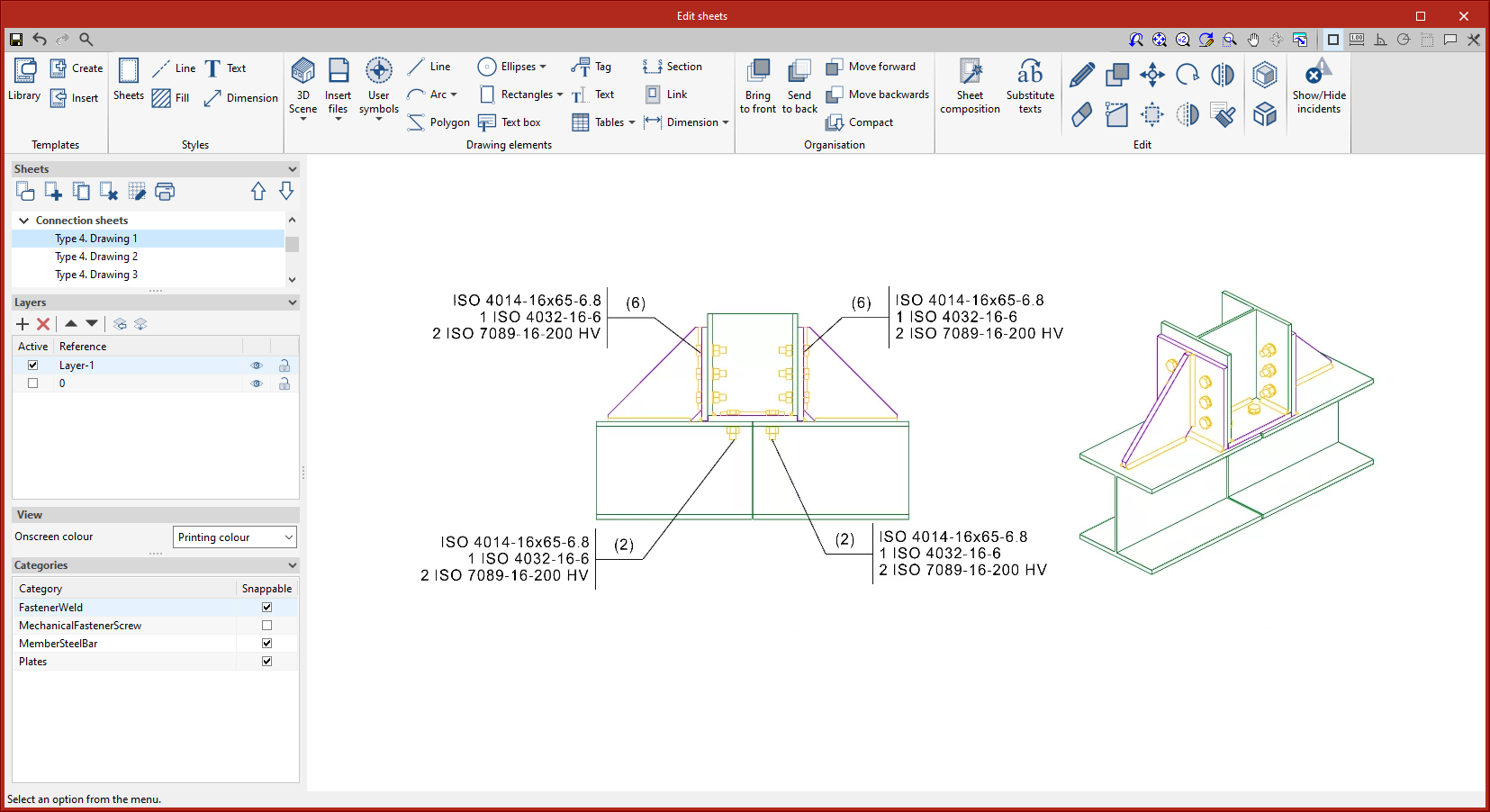
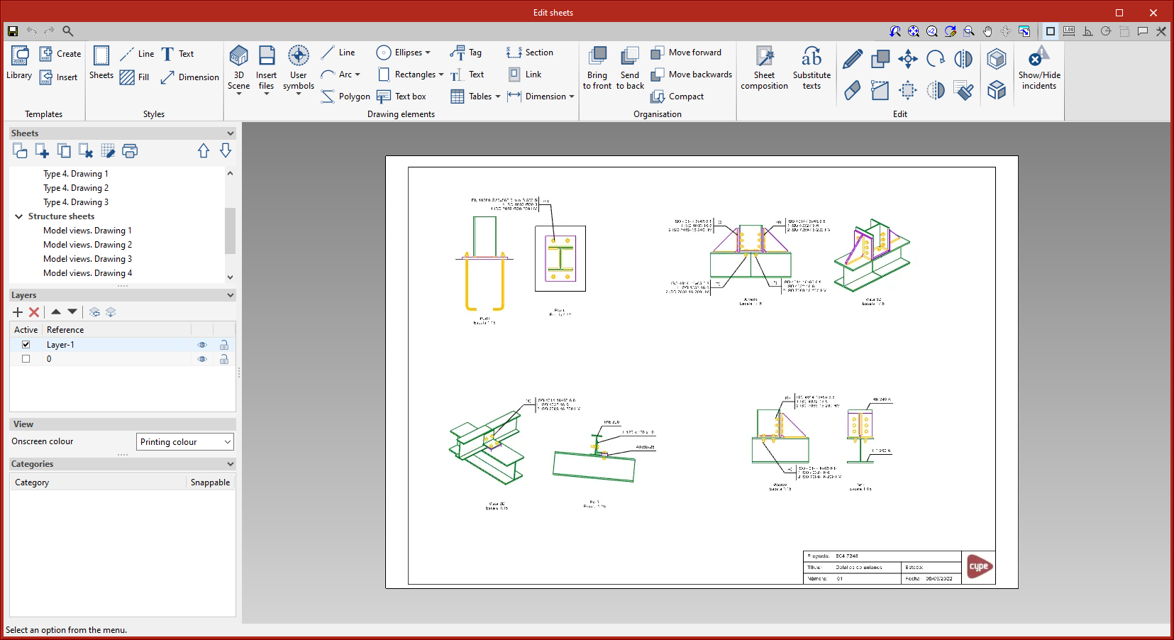
Joints
This tool provides access to the drawing and editing panel of the joint sheets of the selected element.
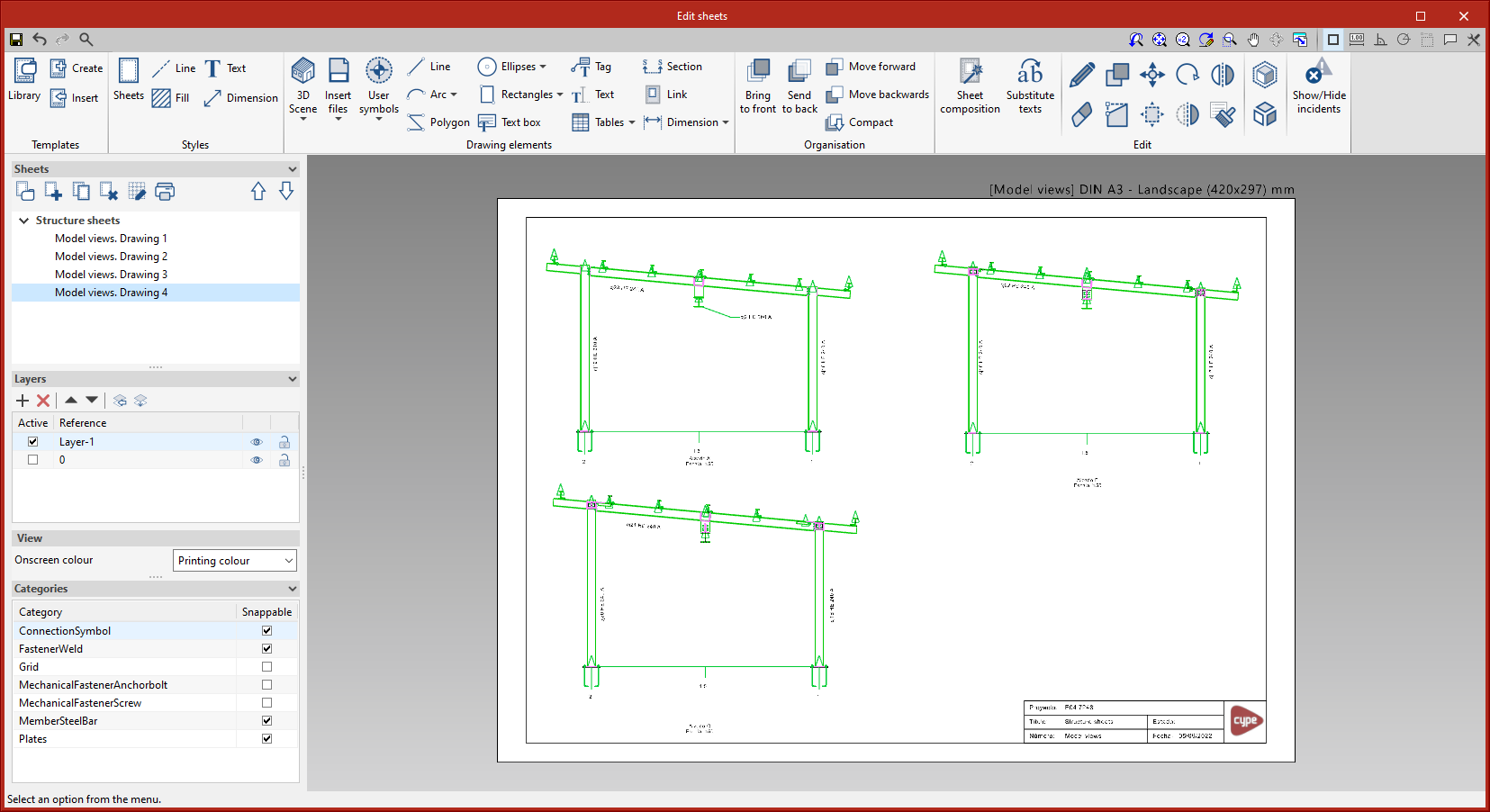
Model views
This tool provides access to the drawing and editing panel of the model sheets, where the different views of the structure will be drawn. Sheets can also be defined as part of the structure, containing the elements of the user's choice, depending on the defined tags.
Composition
From the “Composition” level, sheets can be created from other sheets, i.e. sheets made up of a composition of drawings from different elements.
The “Link” tool allows a reference to the content of one sheet to be inserted into another, while the “Sheet composition” tool generates a mosaic with the selected sheets.
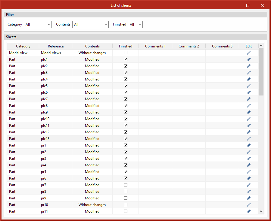
List
In the “List of sheets” dialogue box, a list of all the sheets in the structure is displayed. From the list, the content of each sheet can be accessed by clicking on “Edit”. The list allows the content to be filtered by category, content type and completion status. The columns “Finished”, “Comments 1”, “Comments 2” and “Comments 3” allow users to add notes or comments to each sheet, as well as to mark them as finished when they consider them so.
Managing the visibility of project elements
The visibility of the different elements needed to model the project can be carried out via four panels on the right-hand side of the program's main interface:
- Views
- Elements read
- Tags
- Own elements
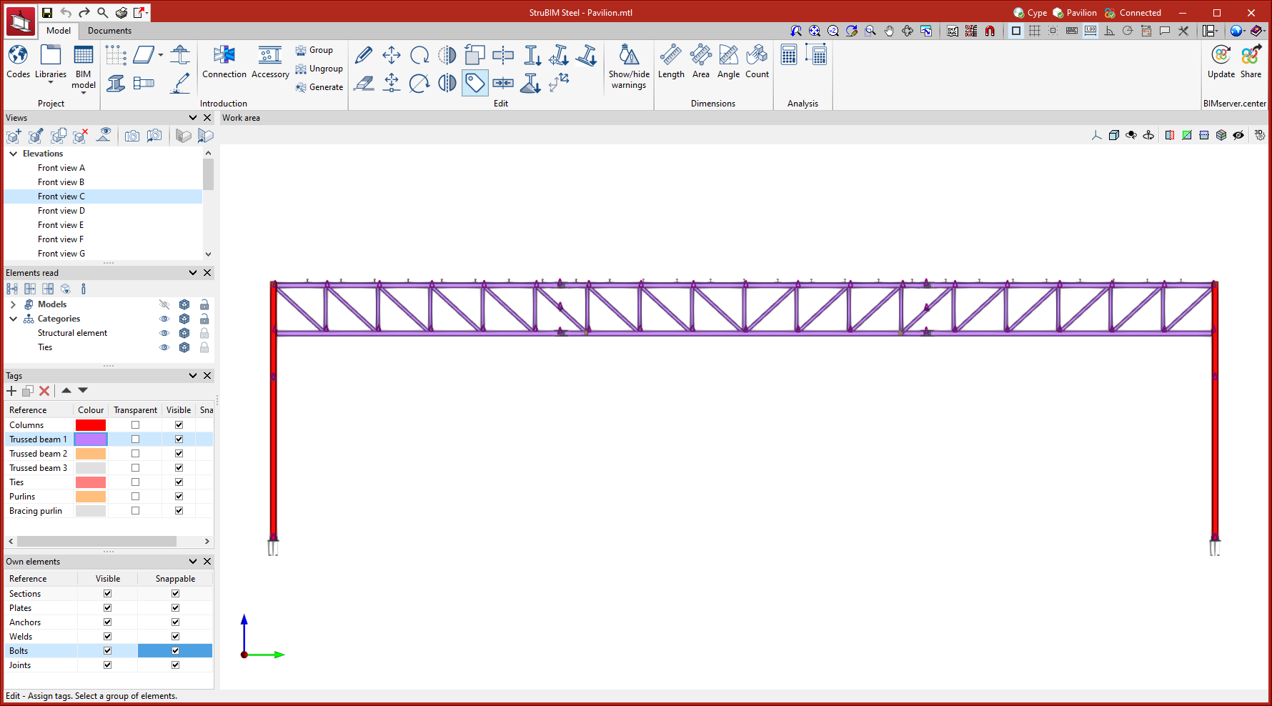
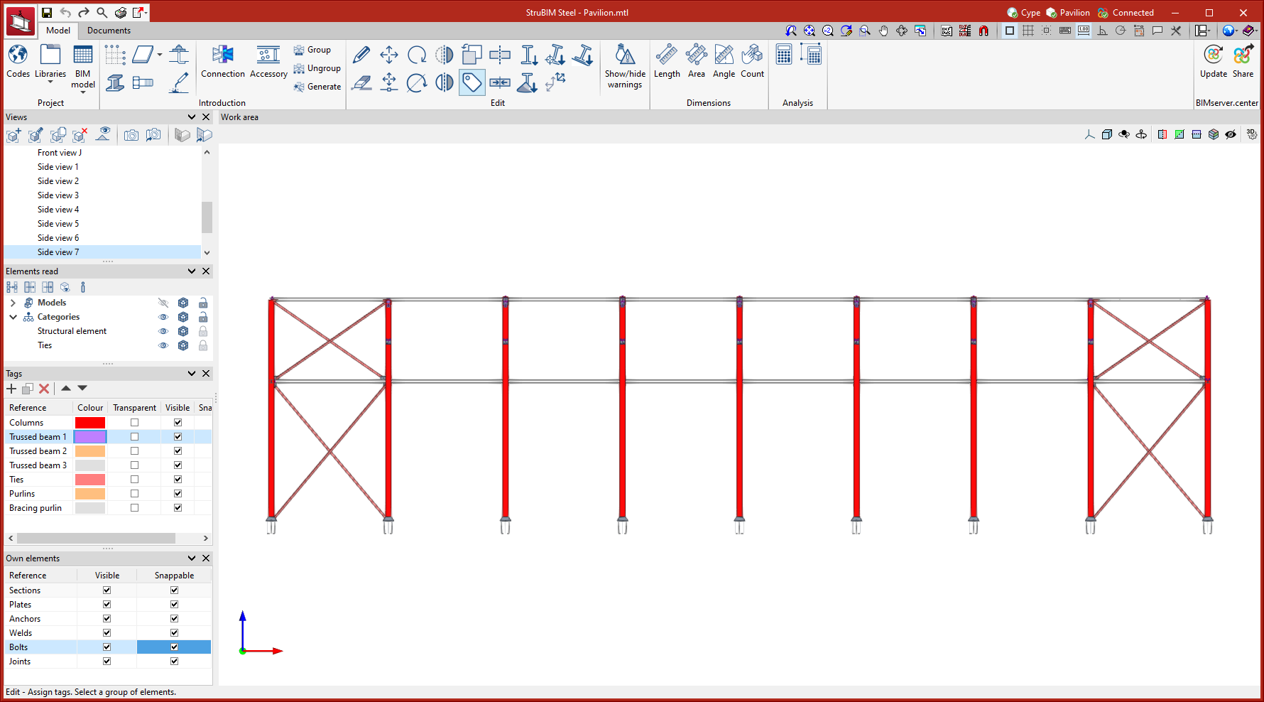
Managing views
Like the other CYPE 3D modelling programs, StruBIM Steel allows different views to be created to make the navigation and modelling process of the structure easier. The following types of views can be created:
- Floor
- Reflected ceiling
- Elevation
- Section
- Generic
- 3D view
| More information: |
|---|
| The system for managing views is a common feature in several CYPE tools. Examples of how to create and enter views can be seen in this CYPE Architecture video. |
Managing elements read
The various models that make up an Open BIM project developed on the BIMserver.center platform can also be imported into StruBIM Steel so that they can be viewed and used as a reference for modelling the structure itself.
Visibility management options allow the following:
- Activating or deactivating elements;
- Changing the visualisation mode of the elements by selecting between "Normal View", "Transparent View" or "Wired View";
- Locking elements so that they cannot be snapped or selected.
Managing the visibility of these models can be carried out in two ways:
- With the "Models" filter, which is applied to the different imported models: architectural model, terrain model, concrete structure, etc.
- With the "Categories" filter, which is applied to the different categories found in the imported models, following the classification of the IFC scheme.
Managing tags
Tags can be created to group the different parts of the model. For each tag created the following can be carried out:
- Defining a reference;
- Defining a colour for 3D representation;
- Activating or deactivating the transparent view;
- Activating or deactivating the visibility;
- Activating or deactivating snapping.
Managing own elements
The visibility and snapping of elements modelled in StruBIM Steel can be controlled from the "Own Elements" menu in the left-hand sidebar of the application.
Results output
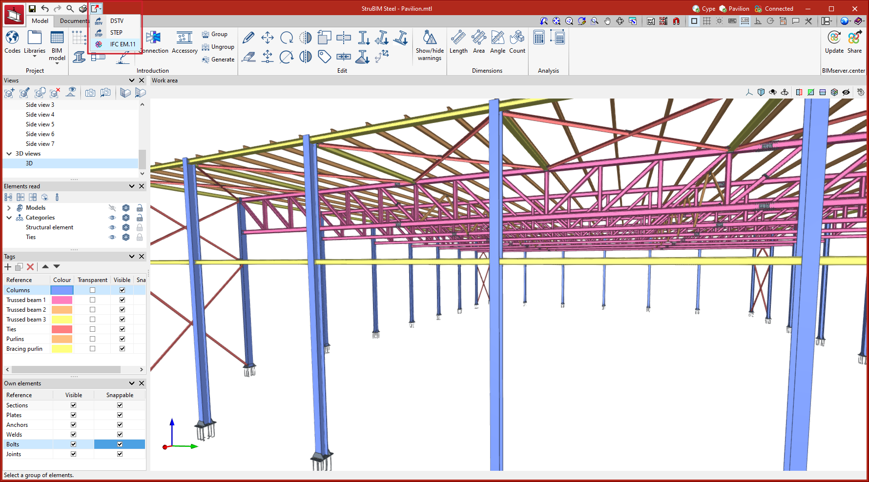
Manufacturing models (DSTV, STEP)

Models in DSTV and STEP format can be exported in two ways: via the export settings of the BIMserver.center platform, and via the options available in the top left corner of the program's main window.
The export options in STEP format can be carried out by including both the complete structure (Structure) and the individual parts (Parts).
The STEP format (ISO 10303) allows the exchange of data between design and manufacturing systems (CAD, CAM, CAE). The DSTV file format is an industry standard defined by the German steel construction association Deutscher Stahlbau-Verband.
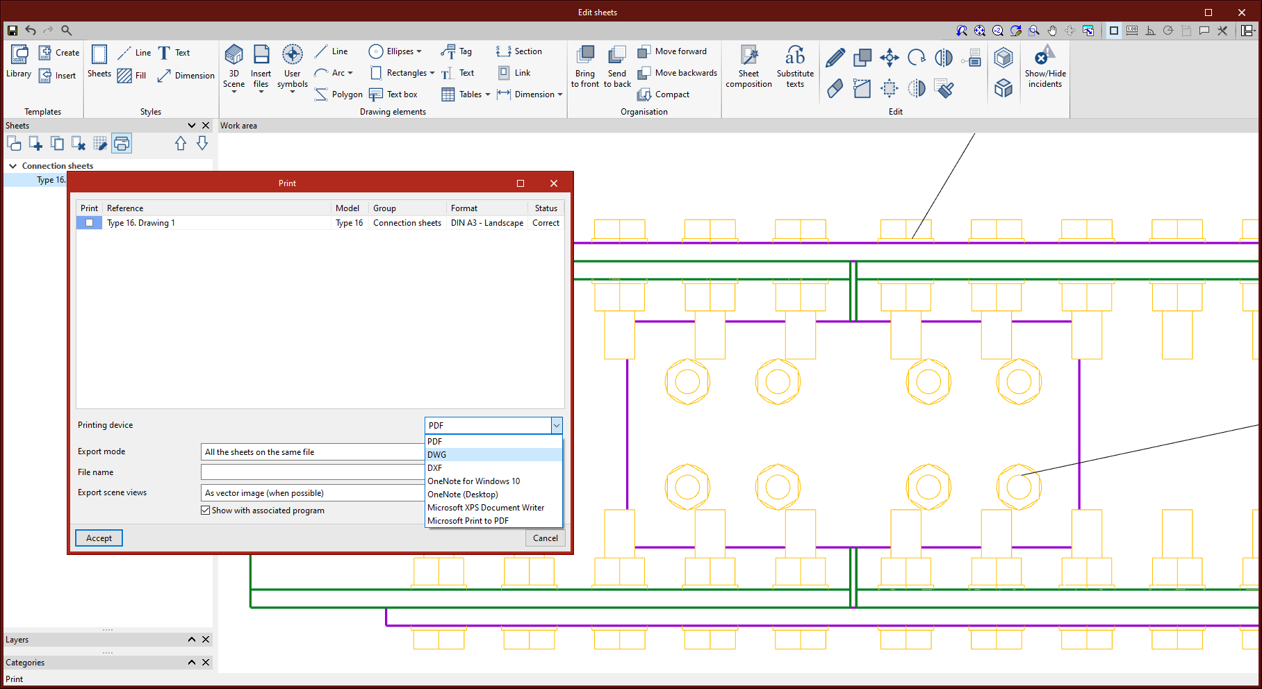
Sheets in DWG, DXF or PDF format
Sheets generated in StruBIM Steel via the options contained in the “Structural steel detailing drawings” module can be exported in DWG, DXF or PDF format.
Export detailing of the steel structure in IFC EM.11 (Exchange Model 11)
EM.11 is an MVD (Model View Definition) specification of the IFC format containing information for automated steel fabrication. StruBIM Steel exports using this format for sections, plates, welds, bolts and screws.
The export to IFC EM. 11 works as a StruBIM Steel module. In order to be used, this module must be included in the StruBIM Steel software license.

Project reports
The following reports can be exported from models developed in StruBIM Steel:
- Codes
- Code check, summary
- Checks
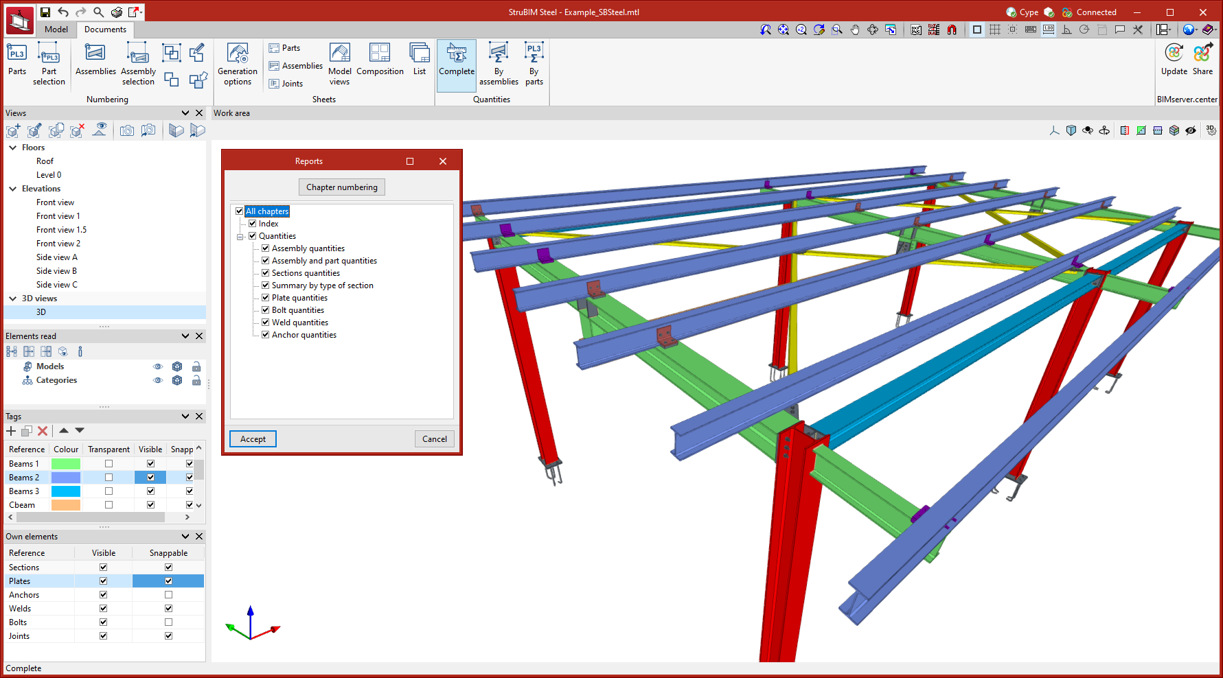
Quantities reports
Within the "Documents" tab, in the "Quantities" group of the main toolbar, you will find the necessary features to generate quantities reports of the elements of the structure.

The options available for generating quantities reports are the following:
- Complete
This option generates a quantities report for the whole structure. - By assemblies
This option generates a quantities report for a selection of assemblies. - By parts
This option generates a quantities report for a selection of parts.
The implemented reports include the following tables:
- Assembly quantities
- Assembly and part quantities
- Sections quantities
- Summary by type of section
- Plate quantities
- Bolt quantities
- Weld quantities
- Anchor quantities
GLTF file compatible with BIMserver.center
When exporting the project to the BIMserver.center platform, a 3D model is automatically exported in GLTF format for integrating the model of the structure into the Open BIM project, allowing the model to be displayed:
- on the online platform;
- in the BIMserver.center application for IOS and Android;
- in virtual reality and augmented reality;
- in other CYPE programs.
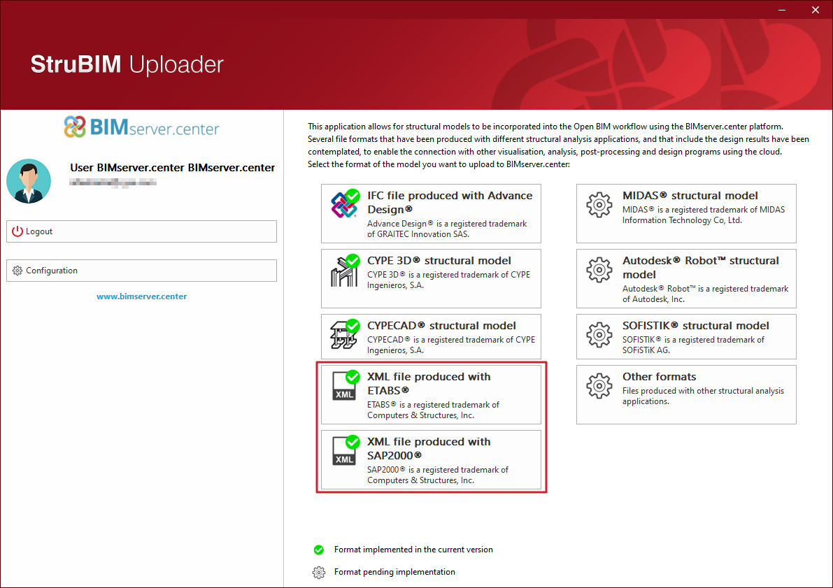
Importing structures from an XML file
From structural programs such as CYPE Connect, StruBIM Steel and StruBIM Shear Walls, structures saved in XML format files can be imported from other programs such as ETABS® or SAP2000®.
This file can be imported and used in CYPE programs in two alternative ways:
- Export the XML file to the BIMserver.center project using the separate program StruBIM Uploader.
In this case, when creating a new job from CYPE Connect, StruBIM Steel or StruBIM Shear Walls, it will be necessary to connect to that BIMserver.center project, and select and import the structural model exported from the StruBIM Uploader.
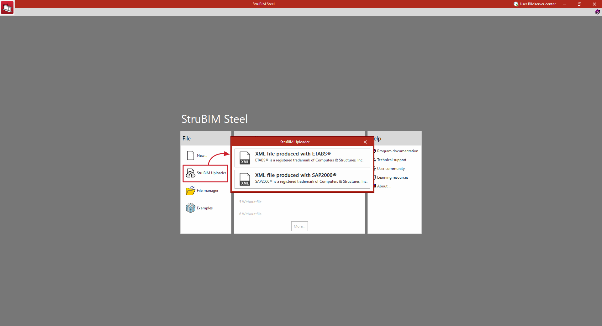
- By directly importing the XML file into CYPE Connect, StruBIM Steel or StruBIM Shear Walls programs, using the "StruBIM Uploader" option integrated in the program and available in the initial interface or in the "File" menu.
After creating a job, this option prompts the user to select a file in XML format from one of the available programs.
In doing so, the ETABS® or SAP2000® structural model is uploaded to an Open BIM project on the BIMserver.center platform (in the same way as the stand-alone "StruBIM Uploader" program would do) and, through an import process, obtains from it the information required to continue the work.
This eliminates the need to use the standalone StruBIM Uploader program.
Importing XML files produced by ETABS®
ETABS® is a registered trademark of Computer and Structures, Inc. The current implementation includes versions "ETABS 2016", "ETABS 18" and "ETABS 21". The following programs can import structures from an XML file generated by ETABS®:
- CYPE Connect
From the information contained in the ETABS® XML, the program imports the bars in the structure and their forces by combination. - StruBIM Steel
From the information contained in the ETABS® XML, the program imports the bars in the structure and their forces by combination. - StruBIM Shear Walls
From the information contained in the ETABS® XML, the program generates the necessary information to perform the shear wall design.
Importing XML files produced by SAP2000®
SAP2000® is a registered trademark of Computer and Structures, Inc. The following programs can import structures from an XML file generated by SAP2000®:
- CYPE Connect
From the information contained in the SAP2000® XML, the program imports the bars in the structure and their forces by combination. - StruBIM Steel
From the information contained in the SAP2000® XML, the program imports the bars in the structure and their forces by combination.
XML file export configuration
For import into CYPE Connect or StruBIM Steel, from ETABS® or SAP2000®, the XML file exported by these programs must contain all model definition tables and all bar force tables.
The export of all these tables can be activated from the export to XML file configuration options in the original program. For example, from the "Choose Tables for Export to XML File" option in ETABS®, the following options must be selected:
- Model definition tables:
- System Data
- Property Definition
- Load Pattern Definitions
- Other Definitions
- Load Case Definitions
- Connectivity Data
- Joint Assignments
- Frame Assignments
- Options and Preferences Data
- Miscellaneous Data
- Bar force tables ("ANALYSIS RESULTS" > "Element Output" > "Frame Output"):
- Table: Element Forces - Columns
- Table: Element Forces - Beams
- Table: Element Forces - Braces
- Table: Element Joint Forces - Frame
For SAP2000®, the tables read by the programs and which are necessary are the following (with the name given to them by SAP2000® in the XML file):
- Program_x0020_Control
- Joint_x0020_Coordinates
- Joint_x0020_Restraint_x0020_Assignments
- Material_x0020_Properties_x0020_02x0020-_x0020_Basic_x0020_Mechanical_x0020_Properties
- Material_x0020_Properties_x0020_03ax0020-_x0020_Steel_x0020_Data
- Material_x0020_Properties_x0020_03dx0020-_x0020_Cold_x0020_Formed_x0020_Data
- Connectivityx0020-_x0020_Frame
- Objects_x0020_And_x0020_Elementsx0020-_x0020_Frames
- Frame_x0020_Offset_x0020_Along_x0020_Length_x0020_Assignments
- Frame_x0020_Section_x0020_Assignments
- Frame_x0020_Local_x0020_Axes_x0020_Assignments_x0020_1x0020-_x0020_Typical
- Frame_x0020_Insertion_x0020_Point_x0020_Assignments
- Frame_x0020_Section_x0020_Properties_x0020_01x0020-_x0020_General
- Frame_x0020_Section_x0020_Properties_x0020_05x0020-_x0020_Nonprismatic
- Load_x0020_Pattern_x0020_Definitions
- Load_x0020_Case_x0020_Definitions
- Casex0020-_x0020_Static_x0020_1x0020-_x0020_Load_x0020_Assignments
- Casex0020-_x0020_Multistep_x0020_Static_x0020_1x0020-_x0020_Load_x0020_Assignments
- Casex0020-_x0020_Modal_x0020_2x0020-_x0020_Load_x0020_Assignmentsx0020-_x0020_Eigen
- Casex0020-_x0020_Modal_x0020_3x0020-_x0020_Load_x0020_Assignmentsx0020-_x0020_Ritz
- Casex0020-_x0020_Response_x0020_Spectrum_x0020_2x0020-_x0020_Load_x0020_Assignments
- Casex0020-_x0020_Modal_x0020_History_x0020_2x0020-_x0020_Load_x0020_Assignments
- Casex0020-_x0020_Direct_x0020_History_x0020_2x0020-_x0020_Load_x0020_Assignments
- Casex0020-_x0020_Frequency_x0020_History_x0020_2x0020-_x0020_Load_x0020_Assignments
- Casex0020-_x0020_Buckling_x0020_2x0020-_x0020_Load_x0020_Assignments
- Casex0020-_x0020_Power_x0020_Spectral_x0020_Density_x0020_2x0020-_x0020_Load_x0020_Assignments
- Casex0020-_x0020_Steady_x0020_State_x0020_2x0020-_x0020_Load_x0020_Assignments
- Combination_x0020_Definitions
- Element_x0020_Forcesx0020-_x0020_Frames
Some of these tables may not appear in the XML file, as they are not exported when empty. In this case, the tables could be optional.
Integration into the BIMserver.center platform
Many of CYPE's programs are connected to the BIMserver.center platform and allow collaborative work to be carried out via the exchange of files in formats based on open standards.
Please note that, to work on BIMserver.center, users can register on the platform free of charge and create a profile.
When accessing a program connected to the platform, the program connects to a project in BIMserver.center. This way, the files of the projects that have been developed collaboratively in BIMserver.center are kept up to date.

| More information: |
|---|
| For further details related to using CYPE software via the BIMserver.center platform, please click on this link. |
Options available in StruBIM Steel
When exporting the project to the BIMserver.center platform, a 3D model is automatically exported in GLTF format for integrating the model of the structure into the Open BIM project, allowing the model to be viewed:

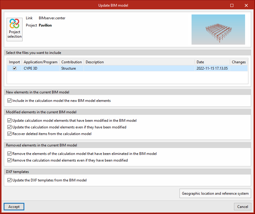
Importing and updating BIM models
The "Update" button can be used to update the information contained in the models previously imported into the project or to import new models if desired.
The import of models is carried out according to the defined configuration, and users can choose how new, modified and deleted elements of the BIM model are shared.
Exporting the BIM model to share it with other users
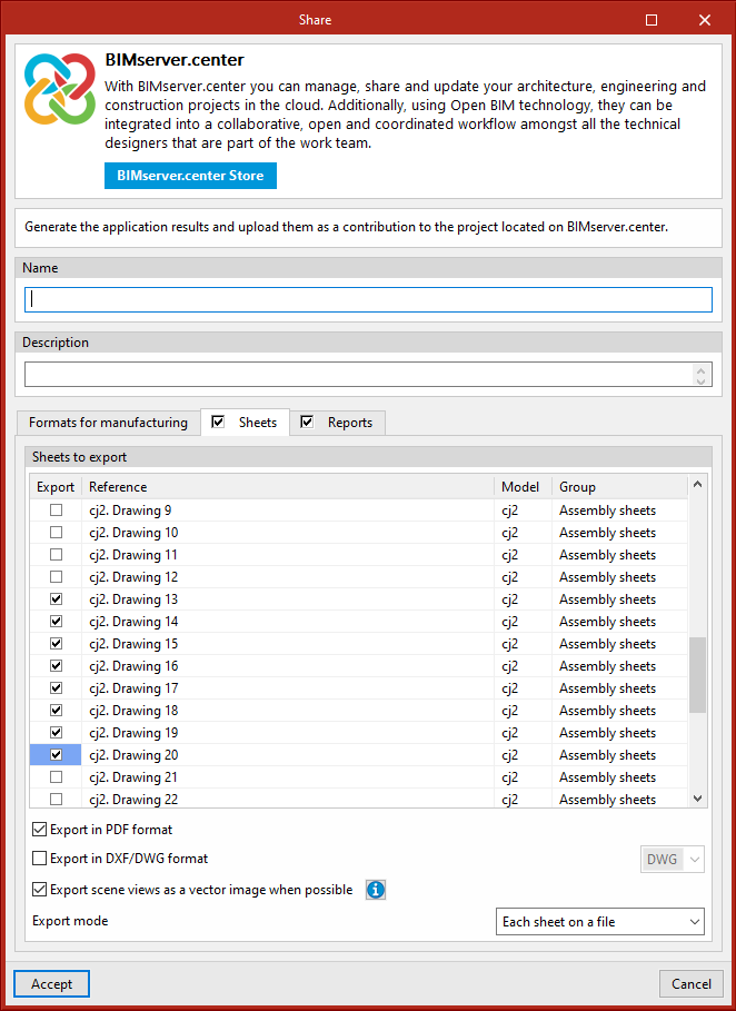
Using the "Share" button, the information contained in the model developed with StruBIM Steel can be exported to BIMserver.center.
During the export process, users can define information related to the identification of the files to be exported, the location of the local copies that are automatically generated and the types of files that are generated.
Users can share the sheets, and the quantities reports and connection checks.
If the "Sheets" tab is activated, the selected sheets will be exported in PDF or DXF/DWG format. Users can also export all sheets as a single file or each sheet as a single file.
If the "Reports" tab is activated, the connection check report and the quantities report can also be exported.