Detailing sheets
In CYPE Connect ("Fabrication" mode), within the "Documents" tab, in the "Sheets" group of the main toolbar, the features required to generate the graphical information of the structure can be found. Using these tools, it is possible to create sheets of elements and parts (sections and plates), assembly sheets, connection sheets and sheets with the general views of the model. From the “Sheets” menu, you can access the “Generation options”, “Parts”, “Assemblies”, “Joints”, “Model views”, “Composition” and “List” tools.
These tools are included in the "Structural steel detailing drawings" module, and their use requires the user license to have the corresponding code for this module.

Generation options
The generation options are arranged in a dialogue box with four tabs: "Parts", "Assemblies", "Joints" and "Model views". They all have common and specific options.
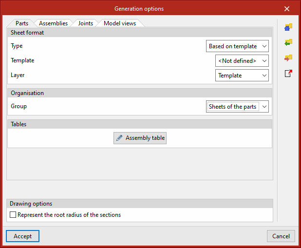

Sheet format (included in all four tabs)
Select the format of the new sheets. In "Type", "Empty" can be selected together with the sheet format or "Based on template" together with the selection of a previously created template and its corresponding layer. The template has a sheet format associated with it.
Organisation (included in the four tabs)
Select the group of sheets in which the newly created sheets will be generated.
Tables ("Parts" and "Assemblies" tabs)
Select the text formatting of the predefined tables in the tabs.
Drawing options (included in all four tabs)
In this section, the option for displaying the chord radius of the sections can be found. This option is deactivated by default.
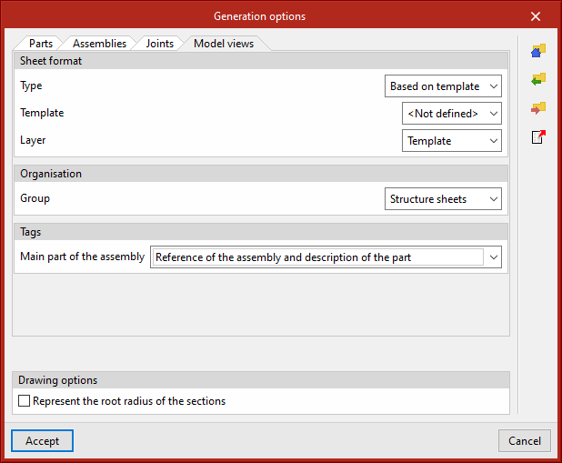
Tags of the “Assemblies” and “Model views” tabs
Select the information that will appear on the automatic tags in the main part of the assembly.
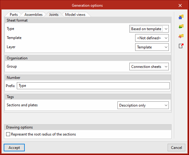
Number (“Joints” tab)
Define a prefix for numbering the joints.
Tags in the “Joints” tab
Select the information that will appear on the automatic tags of sections and plates.
All generation option settings can be saved in the user library. User libraries can be managed via the options buttons on the right-hand side of the “Generation options” dialogue box.
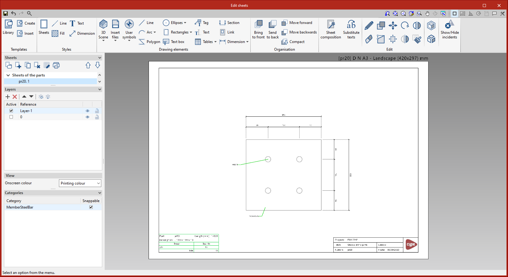
Parts
This tool provides access to the drawing and editing panel of the sheets of the parts of the selected element. In the sheets of the parts, only one element (section or plate) is shown and its geometry is graphically documented. In these sheets, the predefined table of uses of the part in assemblies can be entered.
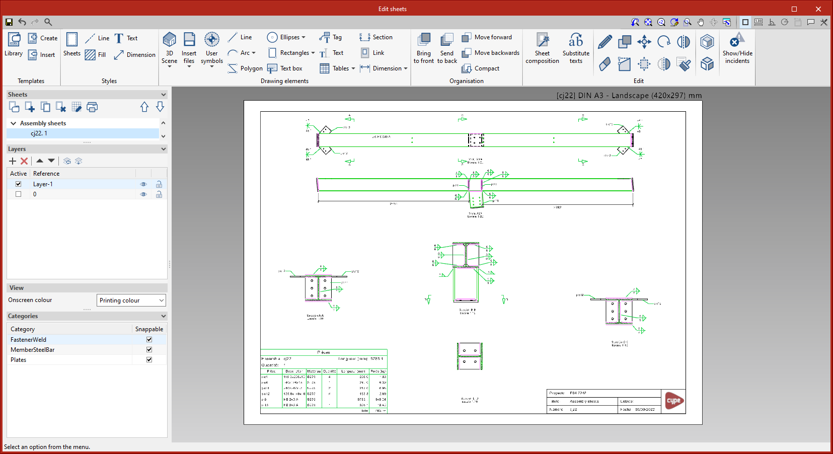
Assemblies
This tool provides access to the drawing and editing panel of the assembly sheets of the selected element. The assembly sheets show all the elements (sections, plates, welds, bolts or anchors) that are part of the assembly being assembled in the workshop. In these sheets, the predefined table of the parts of the assembly can be entered.
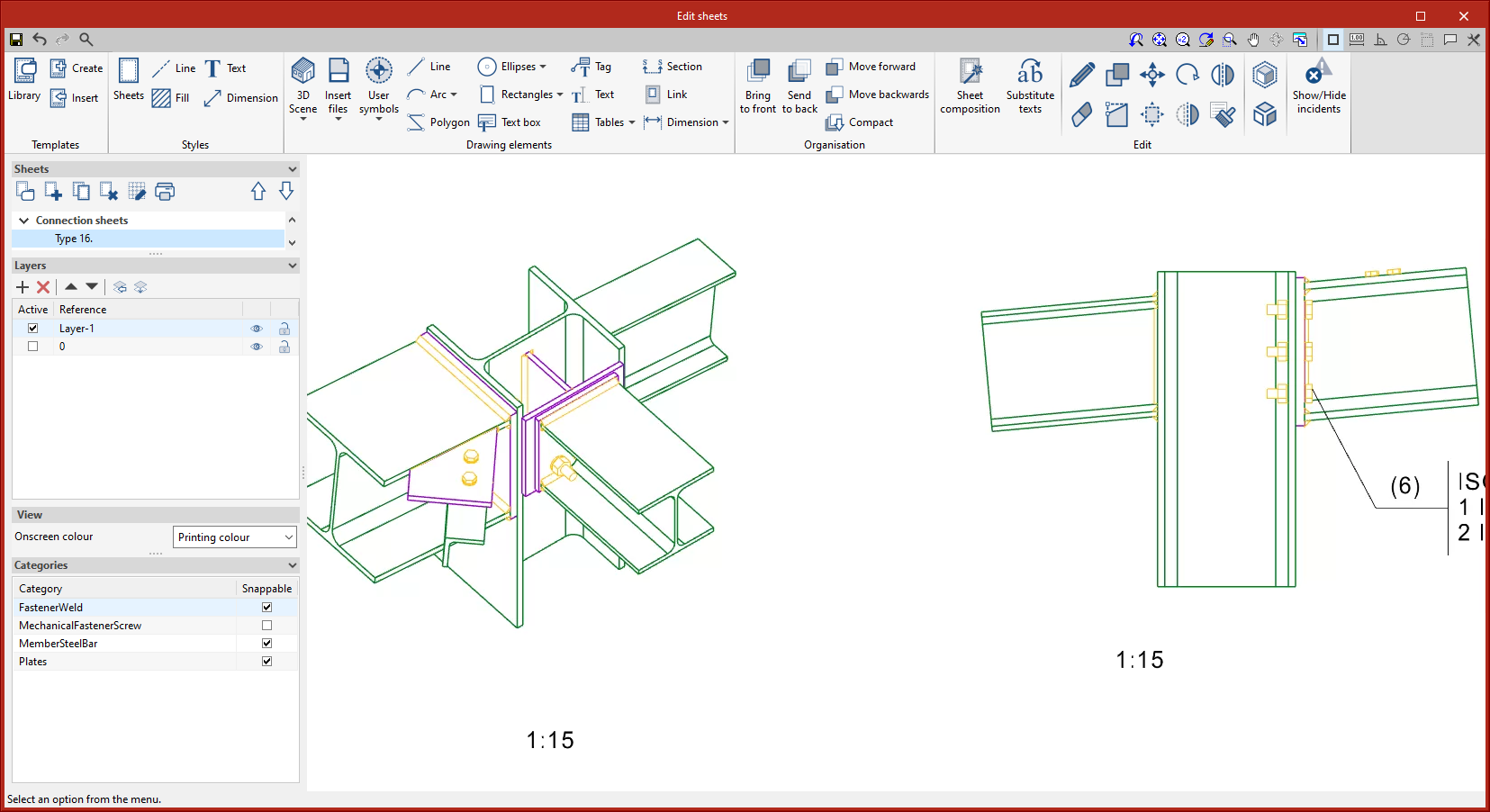
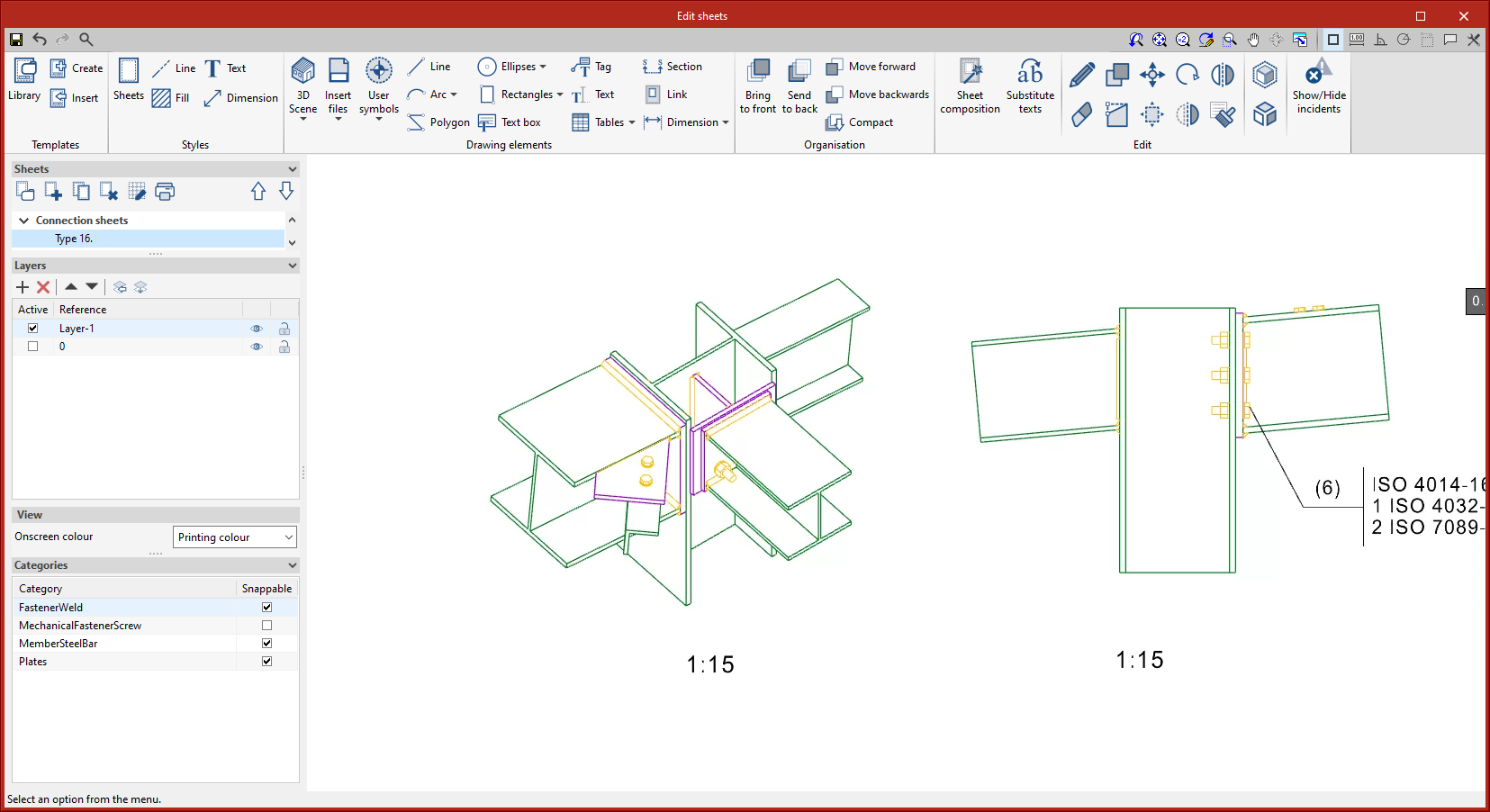
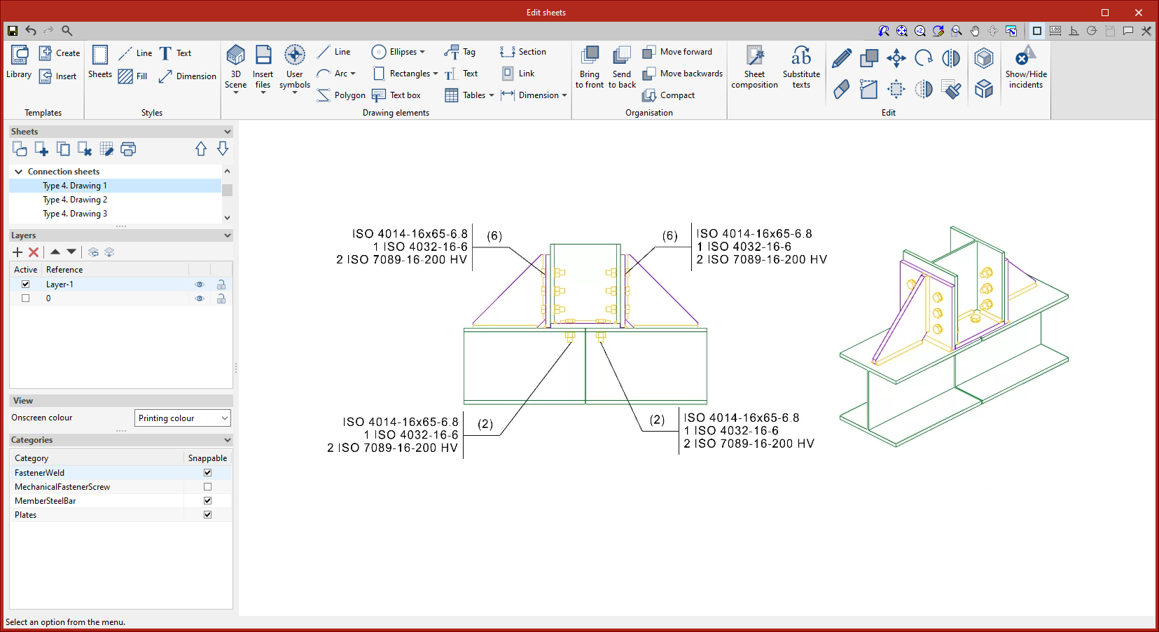
Joints
This tool provides access to the drawing and editing panel of the joint sheets of the selected element.
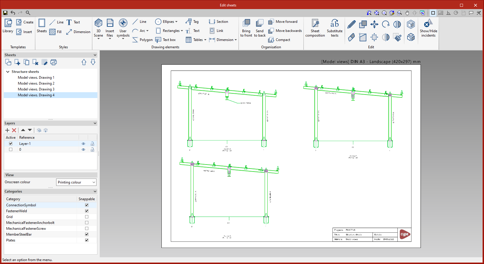
Model views
This tool provides access to the drawing and editing panel of the model sheets, where the different views of the structure will be drawn. Sheets can also be defined as part of the structure, containing the elements of the user's choice, depending on the defined tags.
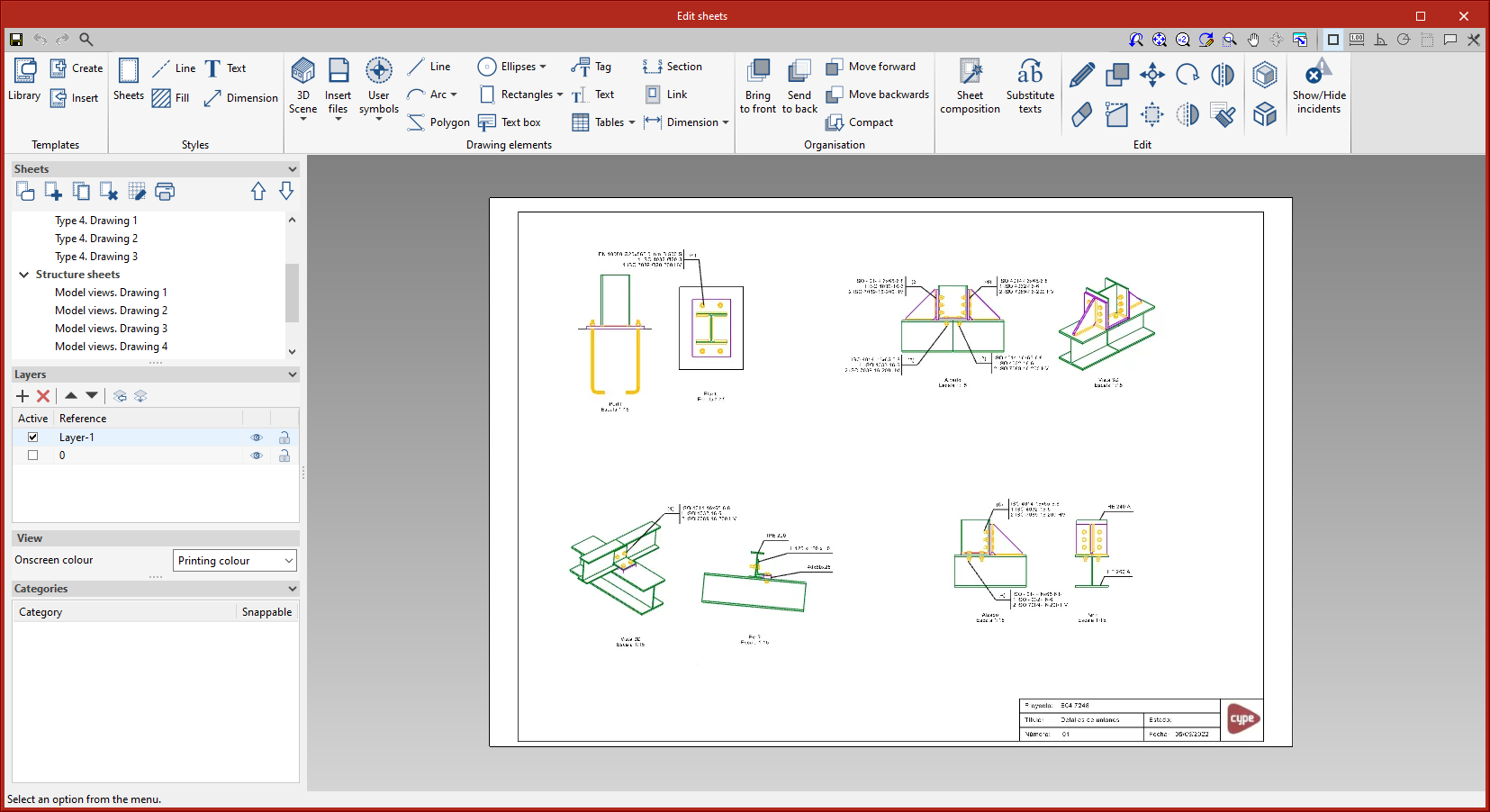
Composition
From the “Composition” level, sheets can be created from other sheets, i.e. sheets made up of a composition of drawings from different elements.
The “Link” tool allows a reference to the content of one sheet to be inserted into another, while the “Sheet composition” tool generates a mosaic with the selected sheets.
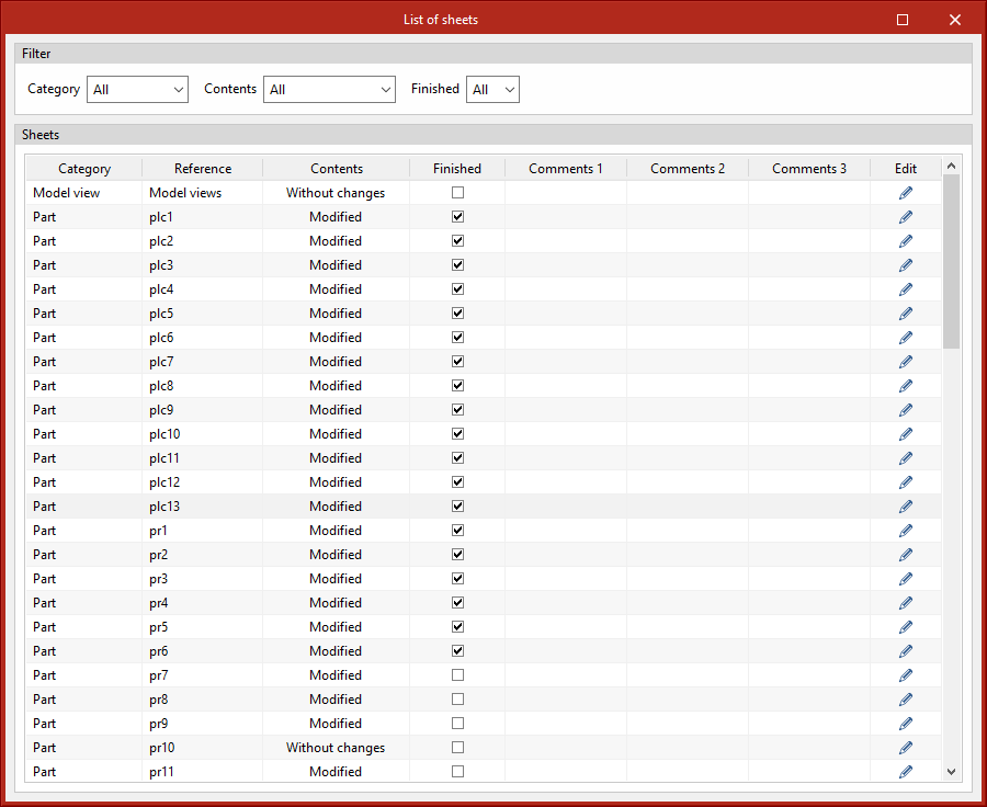
List
In the “List of sheets” dialogue box, a list of all the sheets in the structure is displayed. From the list, the content of each sheet can be accessed by clicking on “Edit”. The list allows the content to be filtered by category, content type and completion status. The columns “Finished”, “Comments 1”, “Comments 2” and “Comments 3” allow users to add notes or comments to each sheet, as well as to mark them as finished when they consider them so.