Introduction
StruBIM Box Culverts is a program for designing and checking reinforced concrete frames used in underpasses roads and drainage works. They can have a freely-designed polygonal layout both in floor plan and elevation drawings, and they can be single-cell or multi-cell.
It can be used for designing frames for prefabrication by defining joints or for in-situ assembly. The section allows users to configure multi-cell box culverts.
The tool includes several assistants to help users enter data for standard cases: straight, skewed, and general box culverts.
The design model used is a 3D thick-shell triangular finite element type, which considers shear deformation. These elements consist of six nodes, at the vertices and midpoints of the sides, each with six degrees of freedom.
Truck loads may be entered in any position, as well as strip loads and loads on slabs.
Workflow supported by the program
The option for connecting StruBIM Box Culverts to the BIMserver.center platform expands the working possibilities offered by the program.
The program can be used on its own to obtain the results it offers independently, but it can also be used to export the modelling results to the BIMserver.center platform to integrate them into the BIM project together with the other layers of information it may contain.
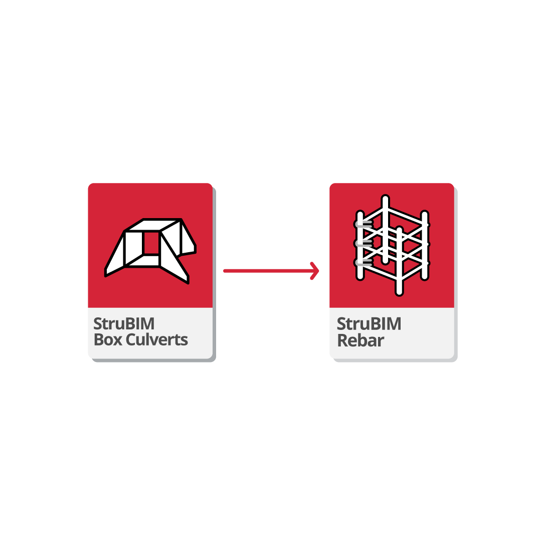
For this purpose, a workflow can be established whereby results generated in StruBIM Box Culverts are imported into StruBIM Rebar, allowing frame reinforcement detailing. As a result, the detailed reinforcement model can be exported in IFC and BVBS format.
Work environment
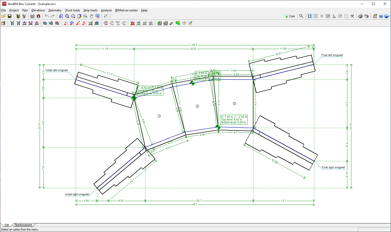
The StruBIM Box Culverts work environment is similar to other CYPE programs
There are two different tabs at the bottom left of the screen: "Edit" and "Reinforcement".
The work area is located in the centre of the screen and displays the characteristics of the project, such as the wing walls, joints or lateral walls, truck loads or strip loads.
The main toolbar contains different features in the "Edit" tab and the "Reinforcement" tab. Users can configure the data and characteristics of the project, define the geometry, as well as enter loads and analyse or design all the elements of the box culvert in accordance with the selected codes, including the top and bottom floor slab, the intermediate cell walls, the lateral walls, and the wing walls and footing.
Assistants
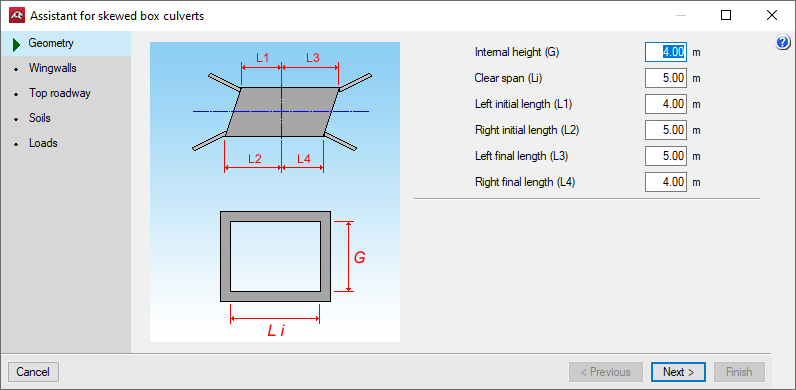
When starting a new job, the program allows users to use an assistant to automatically generate the data necessary to describe the job (depending on the type of assistant selected) from a small number of parameters entered sequentially.
Several assistants are available to help with data entry for common cases:
- Assistant for straight box culverts
- Assistant for skewed box culverts
- Assistant for general box culverts
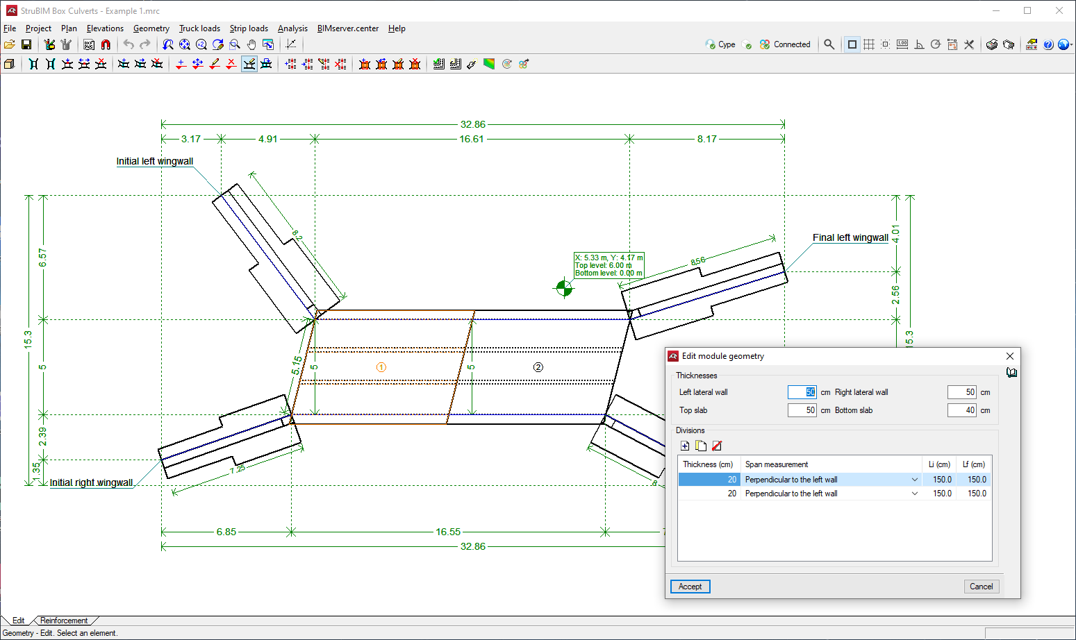
Editing modules
Portal frames are made up of modules that are slabs with lintel and screed embedded in two lateral walls. The interior of the module (cell) can be single-cell or multi-cell, where one or more central walls are added to the last two lateral walls in which the lintel and the slab or foundation slab are also embedded. All of these slabs are of constant thickness.
The geometry of each module can be edited to modify slab and lateral wall thicknesses, and divisions can be added to generate multi-cell boxes.
The top and bottom ground elevations can be assigned in order to define sloping planes. The lateral walls will always remain vertical.
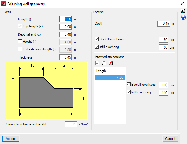
Wing walls
The wing wall is an element that is separate from the main body.
It is made up of a reinforced concrete wall working in a constant thickness corbel embedded in the continuous footing, with variable front and rear overhangs depending on the height of the wall.
By activating specific options, several types of wing walls can be defined.
The geometry of the wing walls can be edited to specify the wall data, such as length or thickness, as well as the footing data, such as depth or overhang in the infill or backfill.
The wing wall footing of a box culvert can also be phased by defining intermediate spans, which are placed consecutively under the wing wall starting from the intersection with the corresponding lateral wall.
Loads
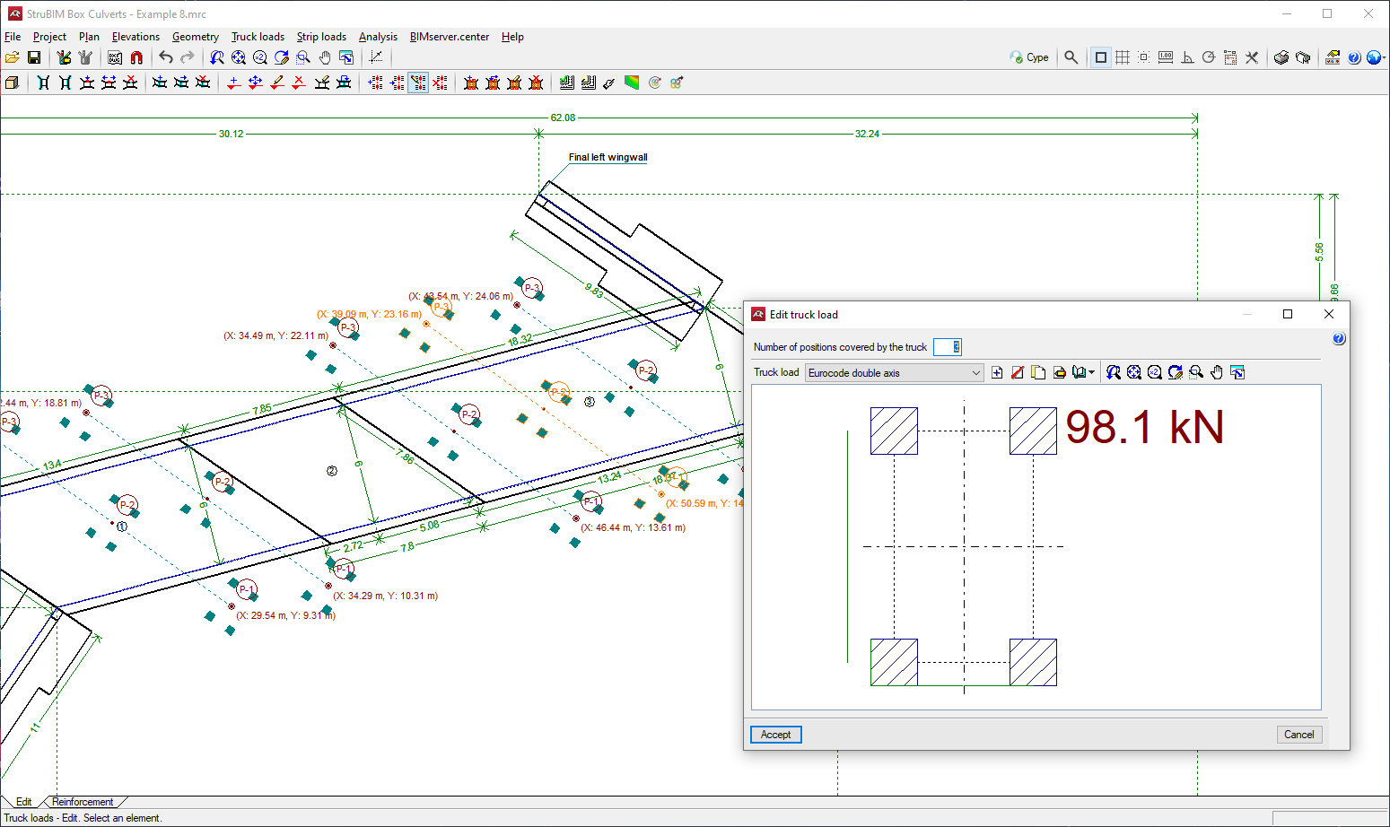
Truck loads can be entered from those existing in different codes and in a wide range of vehicle libraries. They can be entered in any position, graphically indicating the trajectory of the axis and the distance between the sequence of positions of the truck loads, strip loads, floor slabs, etc.
Allows users to add, delete, duplicate and edit truck loads, and to select a truck load from the existing ones in the libraries.
Users can also enter hydraulic loads acting on the screed and internal walls of a box culvert made up of one or several modules.
Force analysis
The analysis model used is composed of a thick triangular finite element mesh, which considers shear deformation. They are made up of six nodes, at the vertices and side mid-points, each with six degrees of freedom.
The wing walls are designed as a bar fixed to the footing subject to earth pressures. They are optionally divided into spans, varying in height and dimensions of the footing.
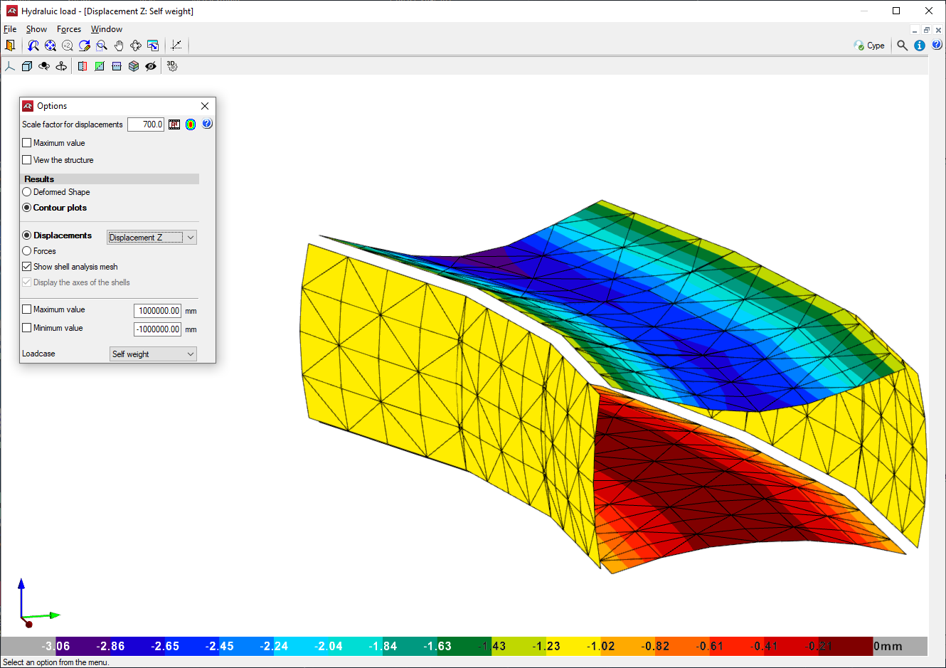
Contour plots
The stress diagram, displacement stress diagram and the deformed shape drawing for any loadcase can be consulted in the 3D view.
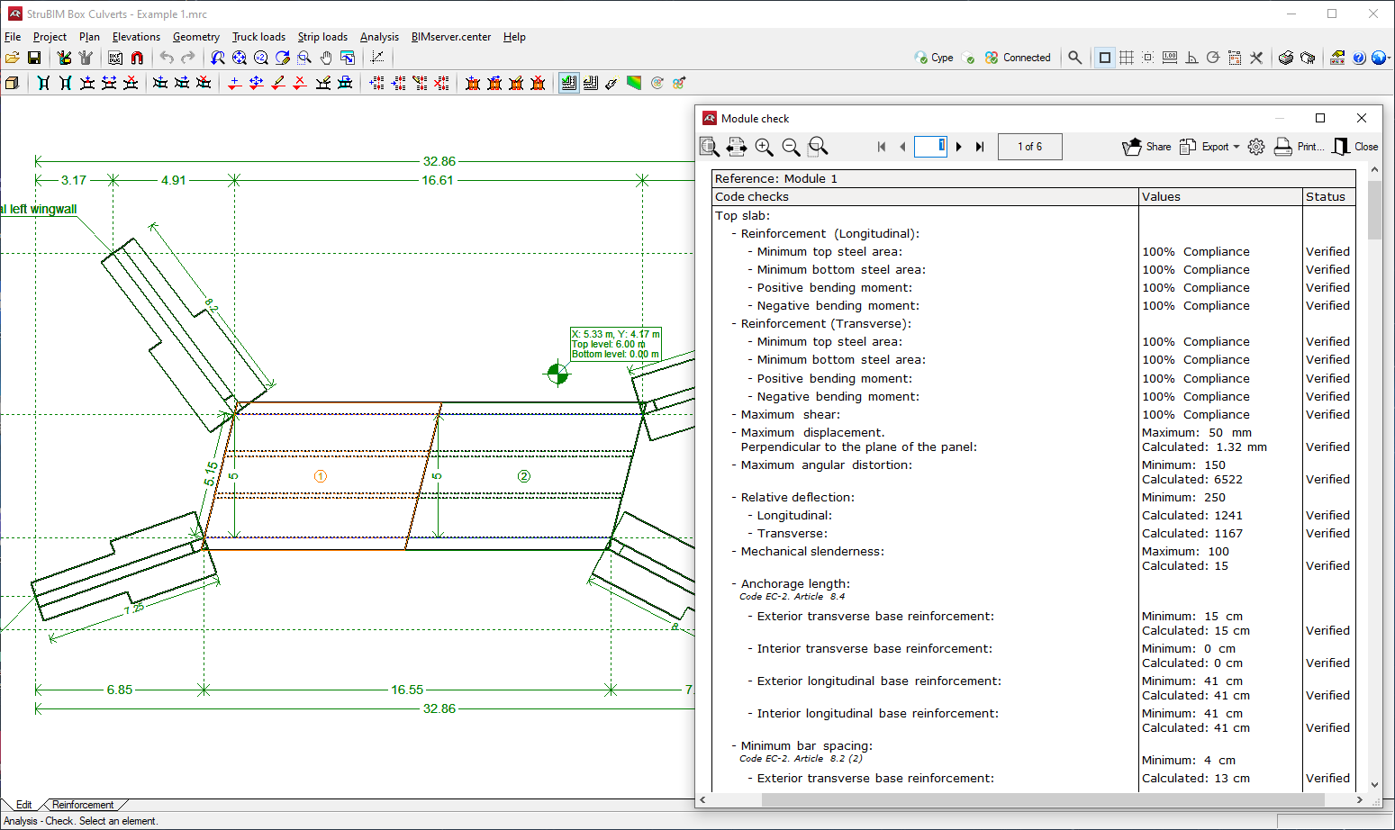
Design and checking
Designs and checks all box culvert elements: top and bottom slab, intermediate cell walls and lateral walls, and wing walls (wall and footing), obtaining the reinforcement for all of them.
Checks the angular distortion in the top slab, bottom slab, lateral walls and dividing walls.
The reinforcement of any selected part of the box culvert can be consulted or edited.
The reinforcement and dimensions of the wall and the wing wall footing can be modified and then checked.
Codes available in the program
The concrete codes implemented in the StruBIM Box Culverts program are the following:
- Código Estructural (Spain)
- EHE-08 (Spain)
- EHE-98 (Spain)
- REBAP and RSA (Portugal)
- BAEL-91 (R-99) (France)
- ACI 318M-11 (USA)
- ACI 318M-14 (USA)
- ACI 318M-19 (USA)
- ACI 318-11 (USA)
- IS 456: 2000 (India)
- Eurocode 2 (EU)
- Eurocode 2 (France)
- Eurocode 2 (Portugal)
- Eurocode 2 (Spain)
- Eurocode 2 (Malaysia)
- Eurocode 2 (Singapur)
- Eurocode 2 (Poland)
- BS 8110-1: 1997 (UK)
- NTC: 14-01-2008 (Italy)
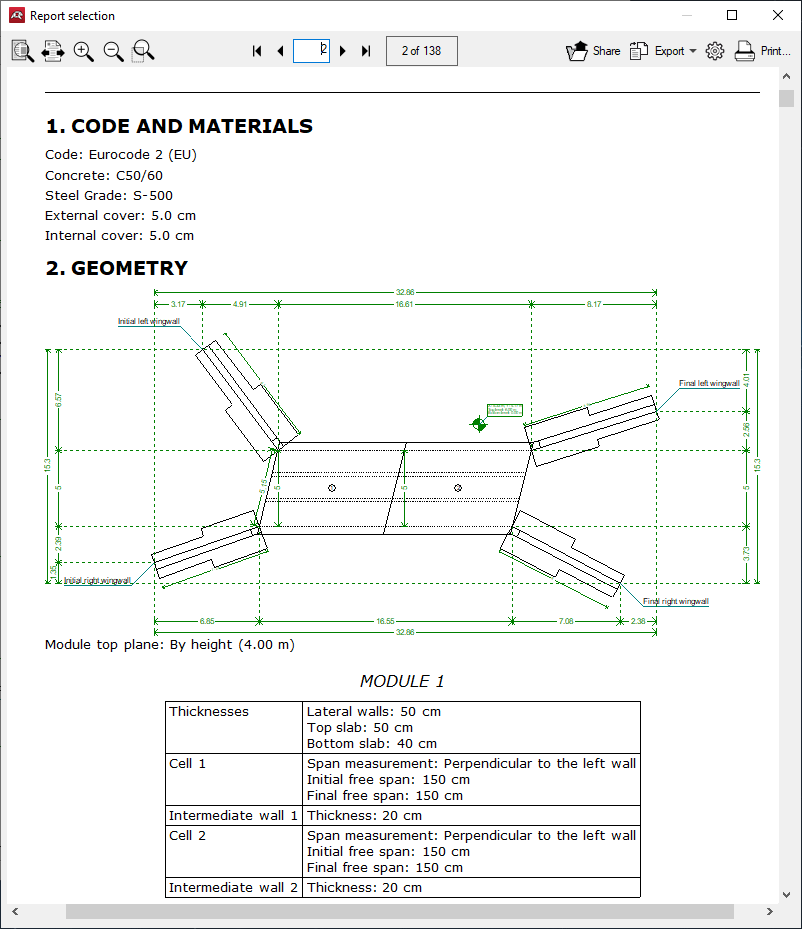
Results output
Project reports
The following reports can be exported from models developed in StruBIM Box Culverts:
- Code and materials
- Geometry
- Soils
- Loads
- Analysis methods
- Results
- Combinations
- Reinforcement description
- Code checks
- Quantities
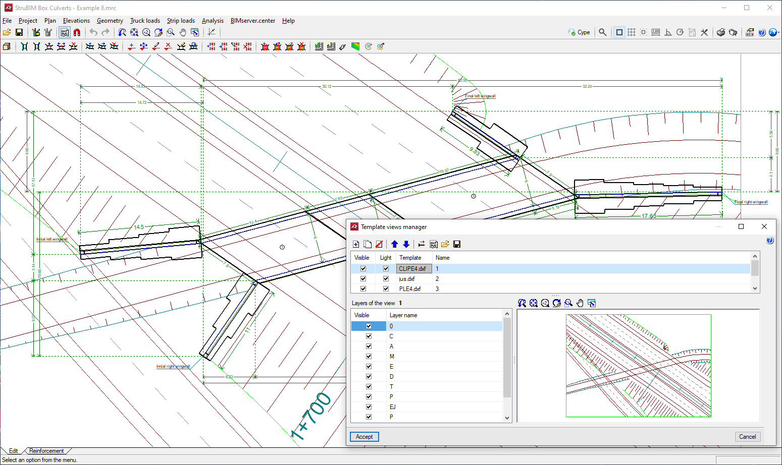
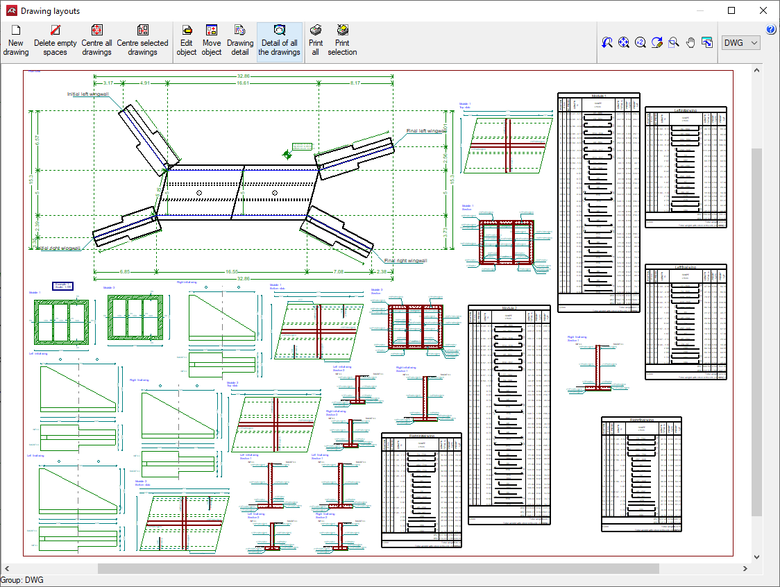
Drawings in DWG, DXF or PDF format
Drawings can be generated with the geometry of the box culvert and detailing of the reinforcement of the modules and wing walls.
Drawings generated in StruBIM Box Culverts can be exported in different formats such as DWG, DXF or PDF.
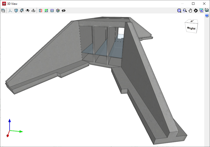
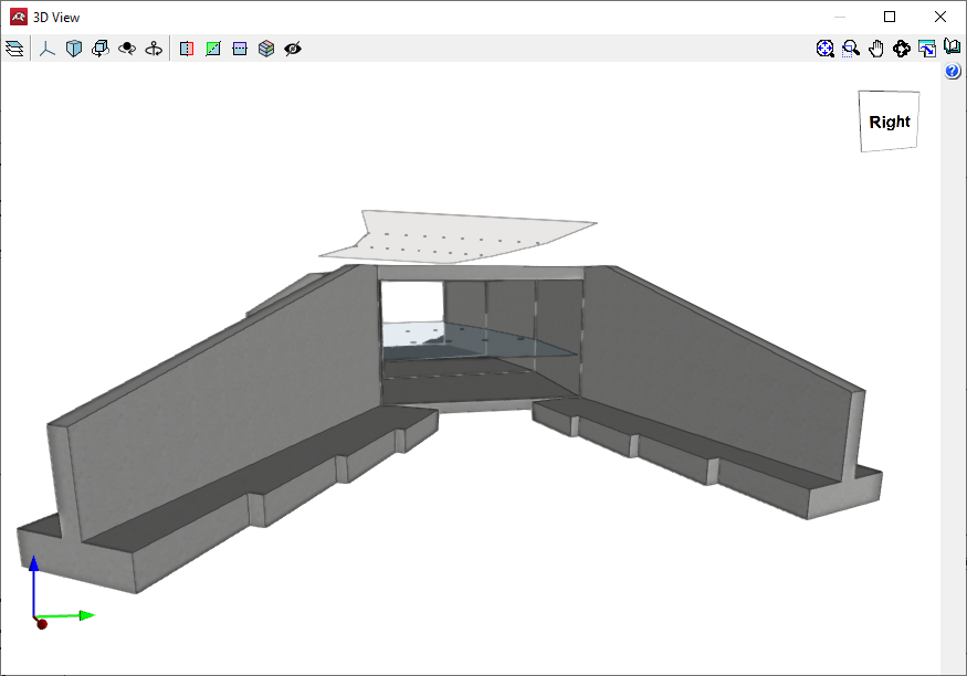
GLTF file compatible with BIMserver.center
When exporting the project to the BIMserver.center platform, a 3D model is automatically exported in GLTF format for integrating the model of the structure into the Open BIM project, allowing the model to be displayed:
- on the online platform;
- in the BIMserver.center application for iOS and Android;
- in virtual reality and augmented reality;
- in other CYPE programs.
Integration into the BIMserver.center platform
Many of CYPE's programs are connected to the BIMserver.center platform and allow collaborative work to be carried out via the exchange of files in formats based on open standards.
Please note that, to work on BIMserver.center, users can register on the platform free of charge and create a profile.
When accessing a program connected to the platform, the program connects to a project in BIMserver.center. This way, the files of the projects that have been developed collaboratively in BIMserver.center are kept up to date.

Options available in StruBIM Box Culverts
In the "Edit" tab, in the "BIM Model" group of the main toolbar, the required features for using StruBIM Box Culverts together with other BIMserver.center tools can be found.
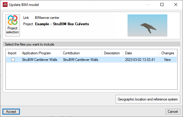
Importing and updating BIM models
The "Import BIM models" option allows users to update the information contained in the models previously imported into the project or to import new models if desired.
Models are imported according to the defined configuration and users can choose how new, modified and deleted elements of the BIM model are shared.
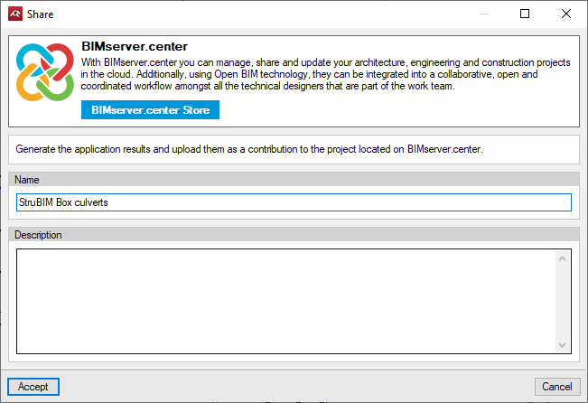
Exporting the BIM model to share it with other users
The information contained in the model developed with StruBIM Box Culverts can be exported to BIMserver.center using the "Generate the application results and upload them as a contribution to the project located on BIMserver.center" option.
During the export process, users can establish information related to the identification of the files to be exported, the location of the local copies that are automatically generated and the types of files that are generated.