Introduction
StruBIM Box Culverts is a program for designing and checking reinforced concrete frames used in underpasses roads and drainage works. They can have a freely-designed polygonal layout both in floor plan and elevation drawings, and they can be single-cell or multi-cell.
It can be used for designing frames for prefabrication by defining joints or for in-situ assembly. The section allows users to configure multi-cell box culverts.
The tool includes several assistants to help users enter data for standard cases: straight, skewed, and general box culverts.
The design model used is a 3D thick-shell triangular finite element type, which considers shear deformation. These elements consist of six nodes, at the vertices and midpoints of the sides, each with six degrees of freedom.
Truck loads may be entered in any position, as well as strip loads and loads on slabs.
Work environment
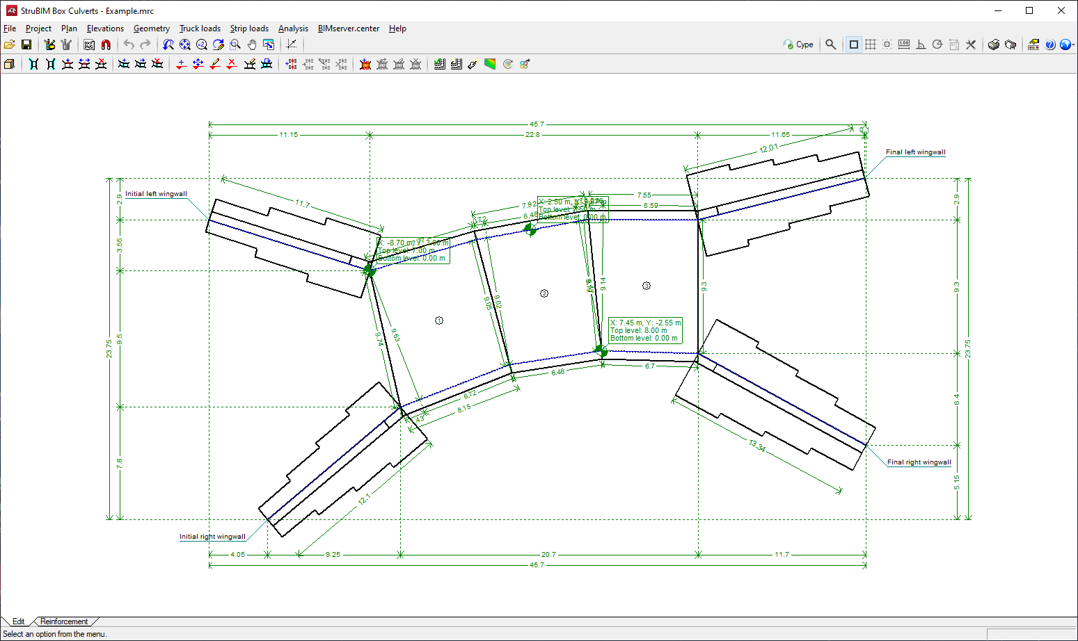
The StruBIM Box Culverts work environment is similar to other CYPE programs
There are two different tabs at the bottom left of the screen: "Edit" and "Reinforcement".
The work area is located in the centre of the screen and displays the characteristics of the project, such as the wing walls, joints or lateral walls, truck loads or strip loads.
The main toolbar contains different features in the "Edit" tab and the "Reinforcement" tab. Users can configure the data and characteristics of the project, define the geometry, as well as enter loads and analyse or design all the elements of the box culvert in accordance with the selected codes, including the top and bottom floor slab, the intermediate cell walls, the lateral walls, and the wing walls and footing.
Creating a new job
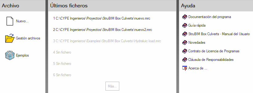
To create a new job, select "New" in the "File" section. Then enter a name for the file and, optionally, a description. The default name is "new".
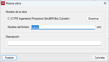
After clicking on "Accept" the wizard appears. If a project is started without the wizard, the BIMserver.center project selection window will open.
Jobs can be linked to BIMserver.center projects. If a job is started with the wizard, this menu will appear after entering the corresponding data.
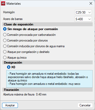
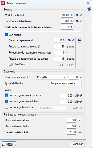
The "Materials" options will then appear, where the concrete settings, bar steel and exposure class can be set along with their designation. After configuring the material settings and clicking on "Accept", the "General data" window opens, where the information relating to the terrain, geometry, loads, and reinforced concrete parameters is configured.
The "Materials" and "General data" options can be accessed at any time during the design process via the "Work" button in the toolbar.
Furthermore, tools such as "Options", "Reinforcement tables" and "3D view" can also be accessed at any time in the same menu.
Assistants
When starting a new job, the program allows users to use an assistant to automatically generate the data necessary to describe the job (depending on the type of assistant selected) from a small number of parameters entered sequentially. This includes the generation of geometry and earth loads, truck loads, strip uniform loads and uniform loads over slabs.
Several assistants are available to help with data entry for common cases:
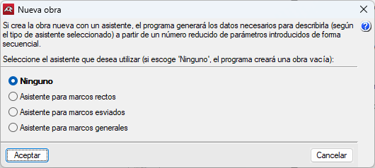
- None
An empty job will be created.
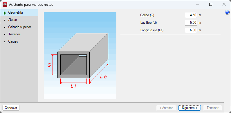
- Assistant for straight box culverts
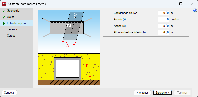
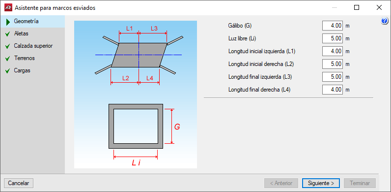
Defines a frame with parallel joints and lateral walls, i.e. rectangular plan. The sequence of data to be entered is shown as an example. For the other frame types, the data to be entered varies slightly. Here, the clear internal height of the modules, the free span between the lateral walls and the total length of the modules are required. The bottom road plane level is not required. This bottom road plane level is given by the thickness of the upper slab, which is a function of the free span (see table below).
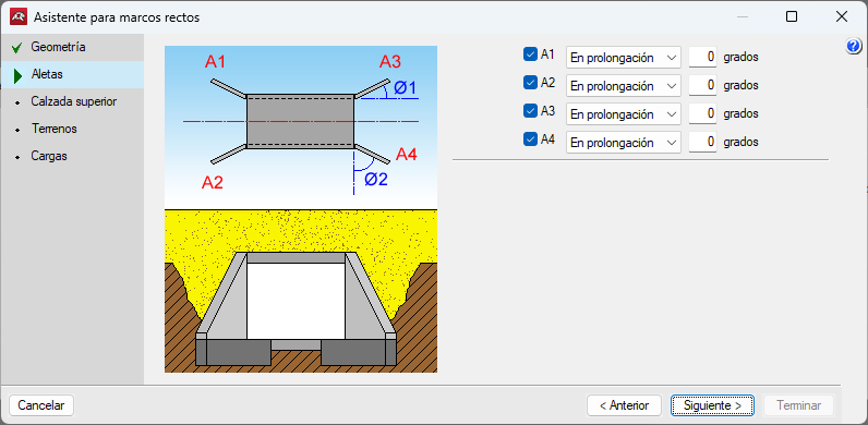
The existence of wingwalls and their angle can be activated or deactivated. The program generates the load on the backfill of the wingwalls as a function of the sine of the angle. For example, assuming an overload of 1 t/m2, an angle of 0 degrees generates 0 t/m2 of overload, an angle of 45 degrees generates 0.7 t/m2, and an angle of 90 degrees generates 1 t/m2.
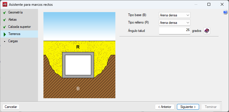
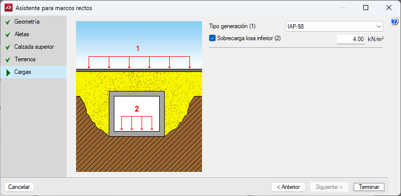
The bottom road plane level is defined and the loads are arranged in strips, with position and rotation to be defined. The base and backfill soils are defined. Then the program requests the type of truck load generation and the overload on the bottom road plane. Finally, a summary of the frame generation parameters is displayed. Once the generation has been completed, users can modify the data as required.

- Assistant for skewed box culverts
Defines a joint frame with any angle and parallel wall.
- Assistant for general box culverts
Defines a frame of joints and parallel wall at any angle.
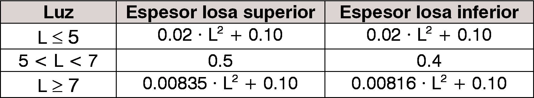
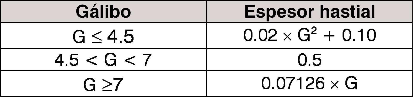
The following thickness design criteria is used for any of the assistants included in the program:
Horizontal road planes are generated in all assistants.
DXF and DWG drawings
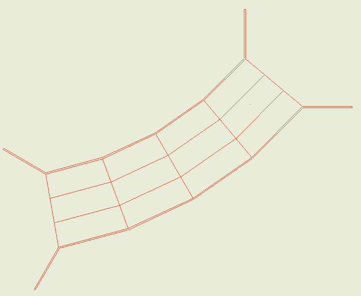
DXF and DWG files can be used as templates for entering the geometry on the plan when assistants aren’t used. If the box culvert drawing is generated with the DXF and DWG file in the background, the template will appear in the drawing.
The geometry is entered via the "Floor" menu options. First of all, the adjustment lines of the lateral walls must be entered. Please note that, by default, the inner faces of the lateral walls are aligned with the adjustment lines, so when entering the adjustment lines, this should be carried out bearing in mind that they are the inner faces of the lateral walls and, therefore, the separation between the right and left lateral wall is the free span. This menu also allows users to indicate which are the joints.
Although it is not essential, if there is a DXF or DWG file where the lateral walls are entered in plan (preferably the line of the interior face), entering the geometry of the frame will be much quicker.
Using the DXF or DWG file as a template for entering the lateral walls is beneficial in comparison to entering them by coordinates, and may be the method used when not using the assistants. When using a DXF file from the CAD program and before exporting, it should be noted that the number should be 3 decimal places. Also, the unit of measurement when importing DXF or DWG is the metre. To import the DXF or DWG file into the program's own format, the following steps must be followed:
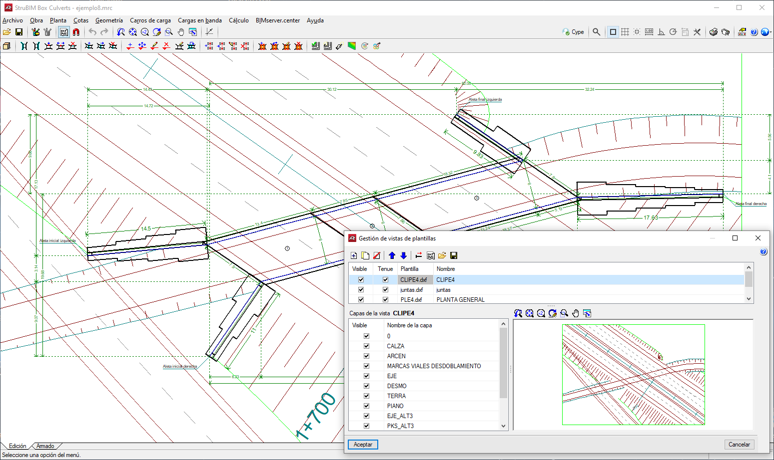
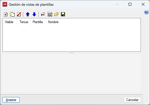
- Select the "Edit templates" icon in the toolbar. The "Manage template views" window opens.
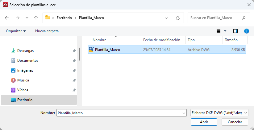
- Click on the "Add" icon, which will open the "Selection of templates to read" window. Choose between DXF or DWG. Browse for the file, select it and click "Open".
- Click "Accept" to return to the "Manage template views" window and click "Accept" again to display it on screen.
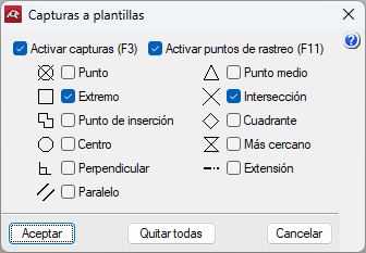
- To use the snaps, click on "Template object snaps" in the toolbar and activate, "Intersection" or "End", for example.
The "New left lateral wall point" option can be used to enter the points of the segments that make up the left lateral walls. The next point always establishes a new lateral wall with respect to the previous point, therefore, the entry must start with the end of the left-hand starting wingwall, continue with the left-hand lateral walls of the modules and end with the left-hand end wingwall.
The "New right lateral wall point" option is used to enter the right lateral wall.
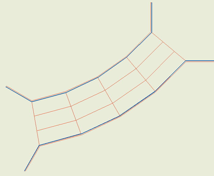
The "New joint" option can be used to indicate the cross faces of the modules. To do this, click on a point in the lateral wall on one side and then the opposite point in the lateral wall on the other side. After entering the two joints, the corresponding module is generated. Once the left and right lateral wall ends have been defined, the joints are inserted.
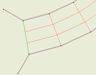
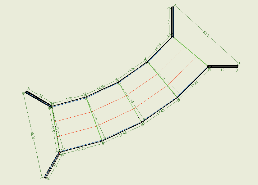
The entry of the joints is shown in each figure below.

Then, after inserting the second joint, the program creates a module (the lateral wall thicknesses are visible) and the wingwalls. After entering the third joint, the second module is created.
Finally, when the last joint is fitted, the floor insertion is completed.
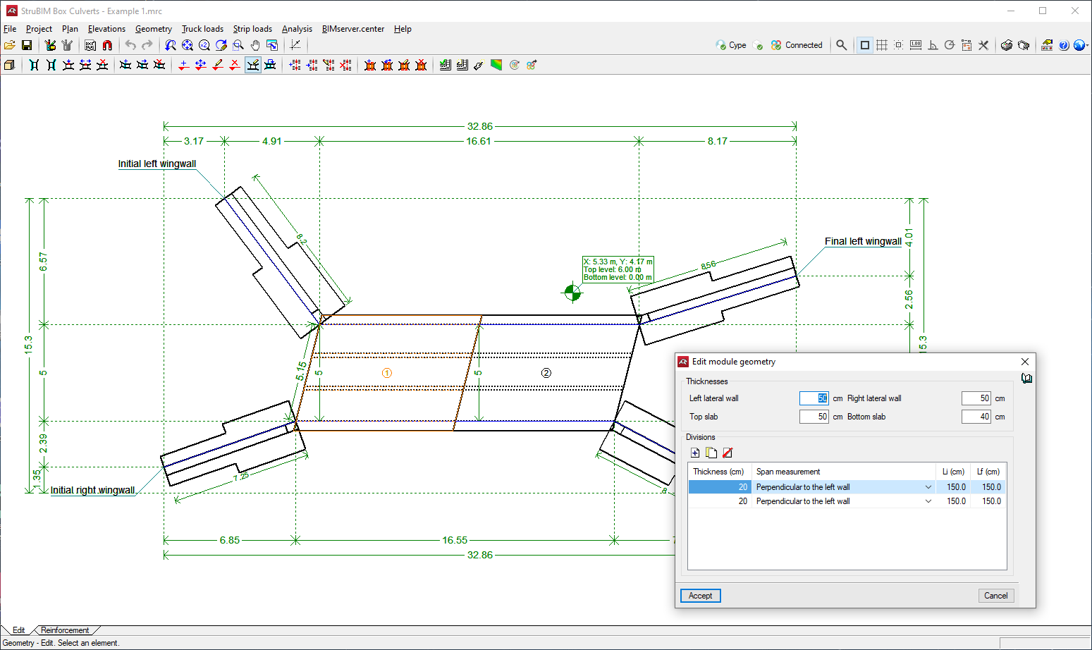
Editing modules
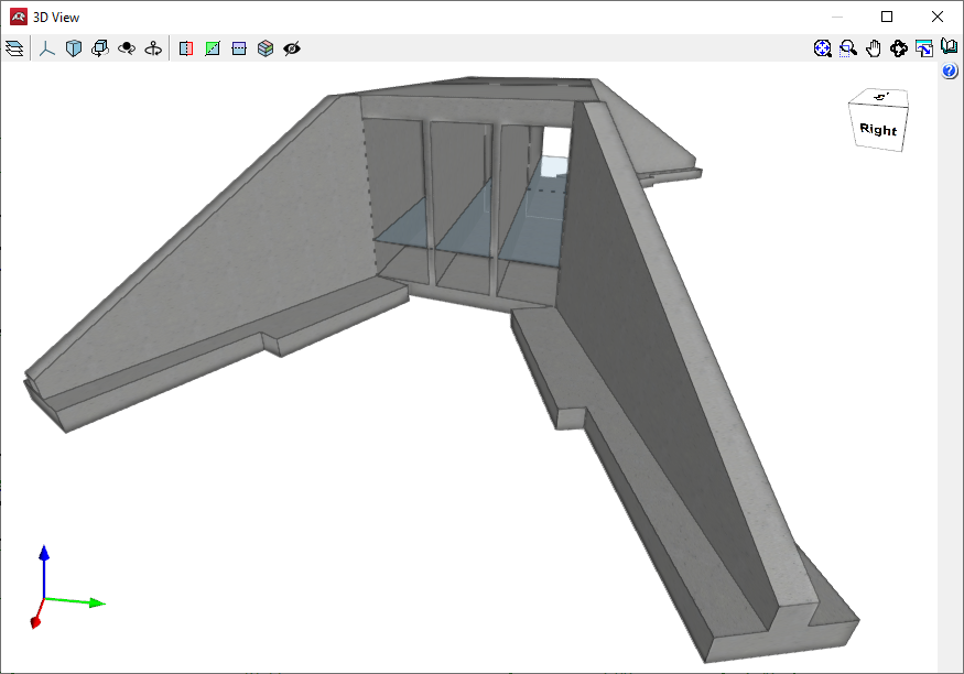
Portal frames are made up of modules that are slabs with lintel and screed embedded in two lateral walls. The interior of the module (cell) can be single-cell or multi-cell, where one or more central walls are added to the last two lateral walls in which the lintel and the slab or foundation slab are also embedded. All of these slabs are of constant thickness.
The geometry of each module can be edited to modify slab and lateral wall thicknesses, and divisions can be added to generate multi-cell boxes.
The top and bottom ground elevations can be assigned in order to define sloping planes. The lateral walls will always remain vertical.
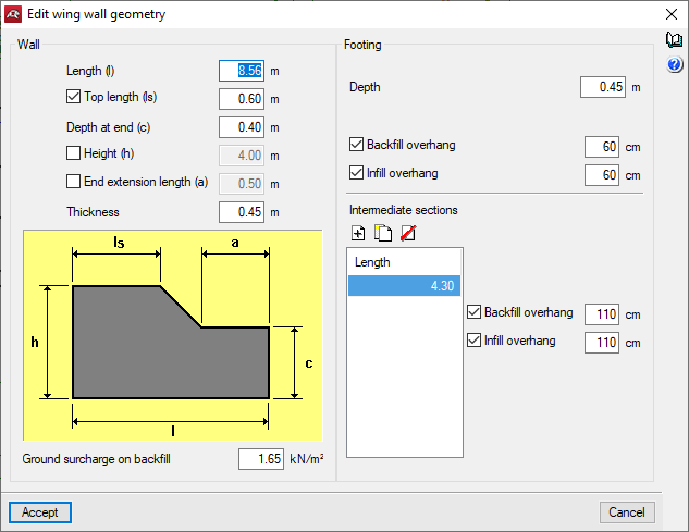
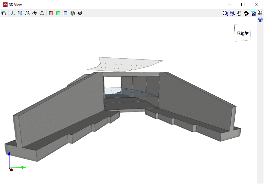
Wing walls
The wing wall is an element that is separate from the main body.
It is made up of a reinforced concrete wall working in a constant thickness corbel embedded in the continuous footing, with variable front and rear overhangs depending on the height of the wall.
By activating specific options, several types of wing walls can be defined.
The geometry of the wing walls can be edited to specify the wall data, such as length or thickness, as well as the footing data, such as depth or overhang in the infill or backfill.
The wing wall footing of a box culvert can also be phased by defining intermediate spans, which are placed consecutively under the wing wall starting from the intersection with the corresponding lateral wall.
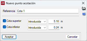
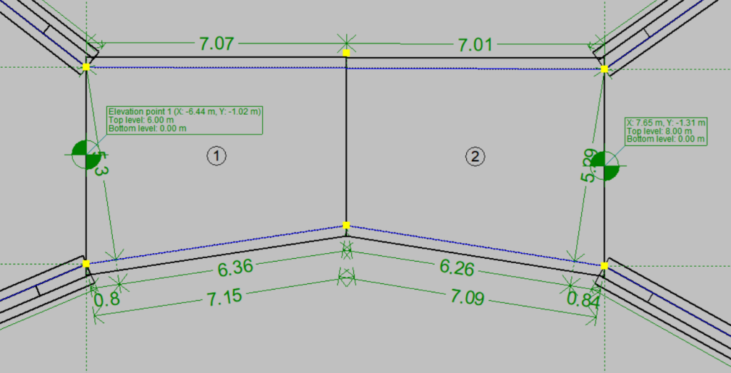
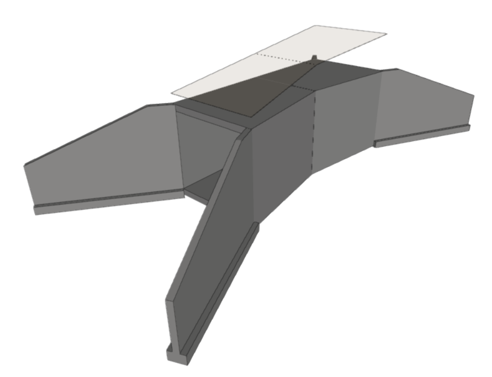
Elevations
The "Elevations" options in the toolbar allow users to manage the vertical elevation profiles of the box culvert design. These tools allow adding, moving, editing, and deleting elevation points providing control over the box culvert’s vertical alignment. To add elevation points, select the "New" tool and then click on the desired point in the box culvert. The "New level point" window will open where a reference name can be entered, as well as top and bottom level elevation points. To change a value, select the "Entered" option.
If different elevation point values are assigned in the modules, a slope in the top surface will be automatically generated.
Loads
In addition to self-weight loads, the program generates the following loads:
Soil pressures
This includes all the actions caused by the soil on the elements of the structure in contact with it. The action of the soil has two components: the weight on horizontal elements (frame lintel, heel of the wing walls) and the thrust on vertical elements (module lateral walls, wing walls).
- The weight of the soil on the horizontal elements is determined by applying the specific weight of the backfill poured and compacted to the volume of soil gravitating on the surface of the horizontal element.
- The estimation of the horizontal pressures is carried out by a two-dimensional analysis, entering sections perpendicular to the walls of the module and the wing walls. The lateral walls of the module are considered to be rigid enough to be able to consider a state of the stress of earth pressure at rest.
The earth pressure at rest coefficient is estimated through the use of Jaky’s formula. If there is a certain slope angle, the additional formulation from the Corps of Engineers, 1961, is applied.
For wingwalls, the pressure of the wingwall on the wall is calculated using the Coulomb method (active pressure coefficient method), considering a slope angle equal to the internal friction coefficient. The slope ends at the level of the top road surface; from this point onward, the soil is considered to be horizontal. The model can consider the cohesion effects and the friction angle between the soil and the wall.
Loads applied on the top road surface
The program defines the variable service and/or exploitation loads applied on the road surface:
Top surcharge
Infinite-extension superficial dead load. Different dead loads can be defined for the modules and each of the wingwalls. Combinations are considered as incompatible with other loads applied on the road surface.
Strip loads
Used to simulate corresponding traffic surcharges on the roadway. Their effect on the wingwalls is not considered.
Truck loads
The available truck loads are described in the Spanish IAP-98, Portuguese RSA, Brazilian NBR, French CBC, Eurocode, and ROM 0.2-90 standards. Additionally, users can define their own truck loads. Their effect on the wingwalls is not considered.
All of these loads are considered to be applied in the Z global direction and only affect the module.
These loads may act on the structure in different ways:
- Effect on the lintel: The loads transfer their action onto the lintel through the fill, which behaves as a distribution layer that projects the load enclosure as a pyramid. The transmission angle can be configured by the user. The surface value of the projected load is determined with the condition that the point value is the same as in the original load.
If no fill is defined or the thickness of the layer is null, the load will be considered as directly applied to the lintel. - Effect on the lateral walls: The loads transfer their action onto the module’s lateral walls through the fill, so that the earth generates additional pressure on them. The loadcase of an at-rest earth pressure state is still valid.
If the load is uniform, the effect of an earth pressure increase is equal to the one caused by the additional height of the earth, of value q 1/(g cos(b)), where b is the slope angle, q is the load value, and the specific weight of the soil.
The effect of point load rigid walls, with prevented displacement, is determined by using elasticity theory. The problem is solved using the Boussinesq approximation, replacing the condition of no wall deformation, with an additional virtual load symmetrical to the real one, with respect to the wall’s backfill.
If the applied action is a strip load or truck load, they are calculated by point load superposition.
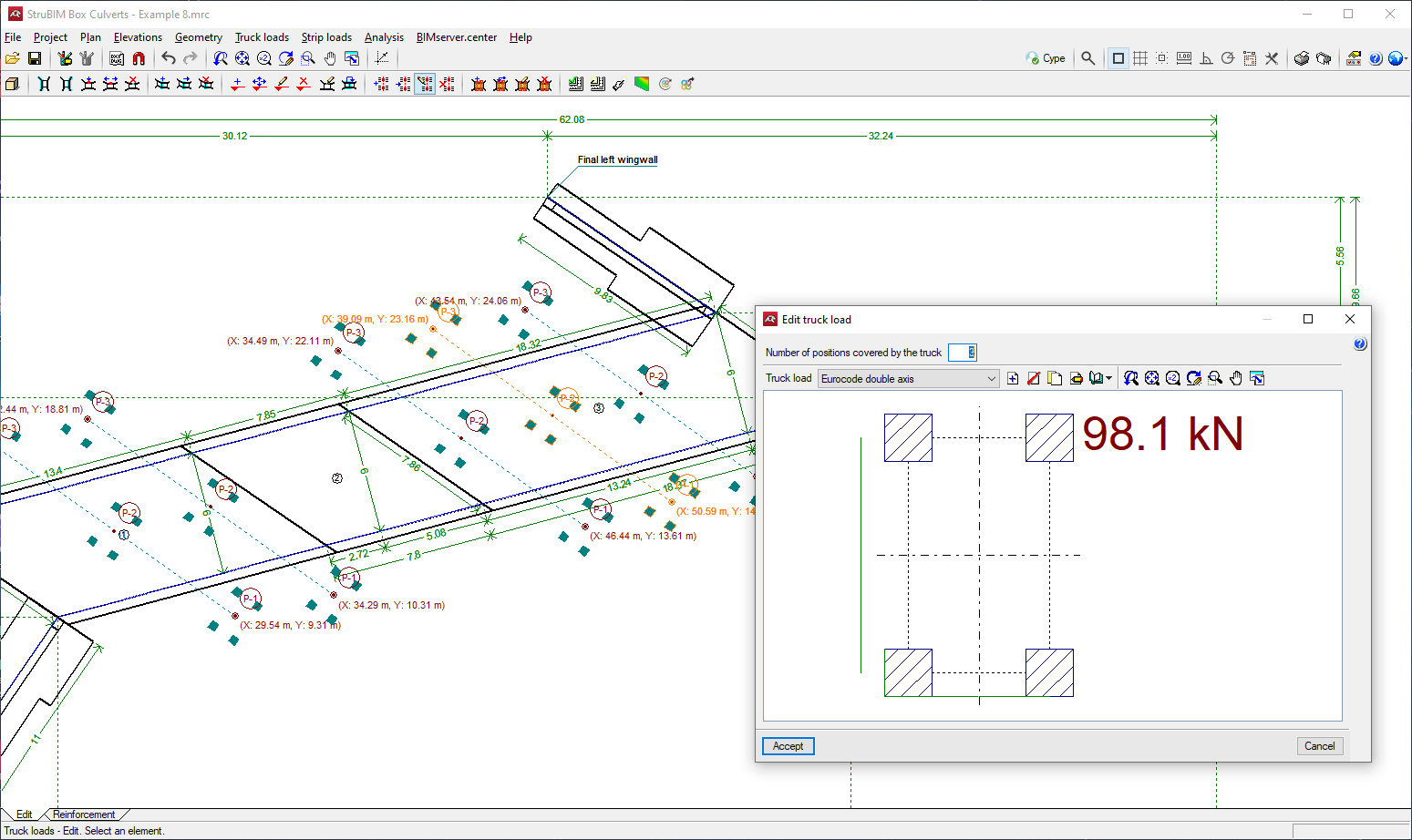
Truck loads can be entered from those available in different codes and in a wide library of vehicles. They can be entered in any position, graphically indicating the axis path and the distance between the sequence of truck positions, strip loads, loads on slabs, etc.
Adds, deletes, duplicates and edits truck loads, and selects a truck load from the existing ones in the libraries.
Loads applied on the bottom slab
Bottom uniform load: Superficial load applied exclusively on the bottom slab of the module.
Hydraulic surcharge
Load caused by a water flow inside the frame. This is evaluated based on a specific weight of water equal to 9.8 kN/m3 . The water pressure is hydrostatic. As for combinations, they are considered incompatible with the bottom uniform load.
Loads of hydraulic origin acting on the screed and inner walls of a single or multi-module frame can be entered.
Completed discretisation
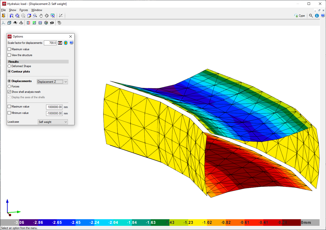
The design model used is a 3D thick-shell triangular finite element type, which considers shear deformation. These elements are formed by six nodes located at the vertices and midpoints of the sides with six degrees of freedom each. A box culvert mesh is generated based on its dimensions (thickness, spans and applied loads).
Consults the stress isodiagrams, displacement isodiagrams and the deformation drawing for any load hypothesis in a 3D view.
The module’s foundation is assumed as a slab supported on an elastic soil with springs at the nodes (ballast coefficient method , according to Winker’s model, based on a proportionality constant between forces and displacements, whose value is the ballast coefficient. This loadcase is valid for homogeneous soils. The ballast modulus is a parameter to be entered into the program. This is determined through empirical methods with a load plate test. Typically, a geotechnical study should provide the exact value of this modulus for the dimensions of the foundation slab.
The wingwall is designed as a cantilevered element. However, if the length of the wingwall is large, the reinforcement is divided into several spans (the minimum length for each span is defined in the design options) and each span will have a different footing size. In the case of variable wall height, each span is discretised into 2-metre-long vertical strips (measured in the floor plan) for the reinforcement. The reinforcement design is based on the worstcase scenario for the largest strip, and this design is applied to the entire wall corresponding to the same segment. For the stability analysis, to stop the wingwalls from overturning and sliding, a single result is obtained for the entire elevation, and it is checked against the entire footing, not the individual strips.
Continuous footing is designed under the wingwall, which can have various configurations: with both toe and heel, only toe, or only heel.
Analysis method
To obtain the loads, the principles of rational mechanics have been considered along with the classical theories of material resistance and elasticity.
The applied analysis method follows limit state principles. The aim is to ensure that the effect of external loads, weighted by certain coefficients, does not exceed the structure’s response, accounting for reduced material strengths (following EHE, RSA, REBAP, and BAEL standards).
For ultimate limit states, checks are made for equilibrium, fatigue, or rupture.
In the states of serviceability, checks are made for deformations (deflections), stresses on the soil and slab separations.
Once the load states have been defined according to their origin, the possible combinations are analysed with the corresponding increase and decrease coefficients, based on the safety factors and basic loadcases defined in the standards.
To determine forces under different simple loadcases, analyses are performed using first-order linear analysis, assuming proportionality between stresses and deformations, the principle of action superposition, and linear geometric behaviour of materials and structure.
To obtain the determining stresses in the element design, the envelopes are obtained for each stress.
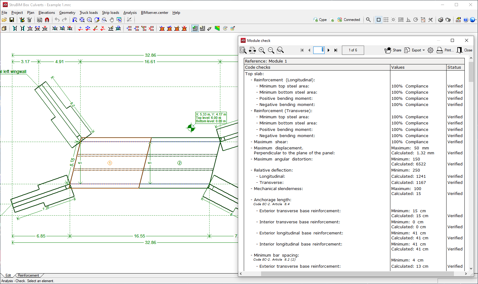
Design and checking
Designs and checks all box culvert elements: top and bottom slab, intermediate cell walls and lateral walls, and wing walls (wall and footing), obtaining the reinforcement for all of them.
Checks the angular distortion in the top slab, bottom slab, lateral walls and dividing walls.
The reinforcement of any selected part of the box culvert can be consulted or edited.
The reinforcement and dimensions of the wall and the wing wall footing can be modified and then checked.
Modules
In each module, eight stresses are obtained through elastic and linear analysis to verify and design the concrete section and reinforcement. Displacements are used to check deflections, stresses on the soil and the detachment of the foundation slab, among others.
The checked states are:
- Minimum geometric reinforcement ratio
In order to control the cracking due to deformations caused by temperature and shrinkage, minimum reinforcements ratios are applied, which vary according to each standard. - Minimum mechanical reinforcement ratio
Minimum mechanical reinforcement ratios are required to prevent brittle failure when the section cracks due to bending moment stresses. - Bending moment check
The structural check of the cross-section is carried out using the simplified parabolarectangle stress-strain diagram as the constitutive law of concrete, which is suitable for delimiting the bending moment rupture stress zone from the non-rupture zone of a reinforced concrete cross-section. The bending moment verification is implemented for all standards supported by the program, with specific considerations for stress integration in the cross-section and the pivots that define the maximum allowable deformations for the materials constituting the cross-section (steel and concrete). For the bending moment check, the reinforcement must be anchored in order to be considered effective in the bending moment analysis. Furthermore, as bending moment stresses act simultaneously with shear stresses, there is an interaction between them. This phenomenon is considered by shifting the bending moment law by a certain distance in the most unfavourable direction. - Shear check
This ultimate limit state is checked in the same way as the bending moment. Since there is no transverse reinforcement in the cross-section, only the contribution of concrete to shear resistance is considered. The contribution of concrete to shear stress is evaluated using the experimental term Vcu. This term is usually included in the tensile fatigue shear check of the cross-section’s web. Various expressions for evaluating the Vcu component have been considered based on the chosen standard. - Maximum displacement and relative deflection
The displacements and deflection for structural elements are limited according to the applicable standard. - Angular distortion
The angular distortion generated in the top slab, bottom slab, lateral walls, and dividing walls, is considered as a serviceability limit state (SLS). - Slenderness ratio
The maximum slenderness of compressed elements, such as lateral walls and module slabs, is limited. - Minimum anchorage hook length
Calculations are carried out in compliance with the various implemented standards. - Minimum reinforcement spacing
The minimum spacing between reinforcement bars according to standards is required in order to allow the concrete to be poured correctly. - Maximum reinforcement spacing
This limit is set to ensure that there are no areas without reinforcement. This is a minimal condition for distinguishing between “reinforced concrete” and “mass concrete”. - Uplift
A check is carried out to verify that there is no upward vertical displacement at any node in the foundation slab, as this would invalidate the analysis (the soil cannot pull the slab). If this occurs, the structure should be checked, by stiffening the slab if possible. - Allowable bearing pressure
The maximum bearing pressure that can be applied to the soil is limited to the value specified by the user.
Wingwalls
The states to be checked are as follows:
- Check for joint shear at base of wall/span
The calculated shear at the joint between the wingwall elevation and the footing is checked to ensure that it is less than what the section can withstand at that point, considering the concrete cross-section and the steel provided. - Minimum thickness
The minimum thickness is restricted according to the standard’s requirements. - Minimum geometric ratio
Minimum reinforcement ratios are imposed to control cracking due to deformation caused by temperature and shrinkage and vary according to each standard. - Minimum mechanical ratio
For vertical reinforcements, minimum mechanical ratios are required to prevent brittle failures when the section cracks due to bending momentum stresses. - Maximum geometric ratio
A maximum ratio is imposed on the total vertical reinforcement. - Minimum reinforcement spacing
The minimum spacing between reinforcement bars according to standards is required in order to allow the concrete to be poured correctly. - Maximum reinforcement spacing
This limit is established to ensure that there are no areas without reinforcement. This is a minimal condition for distinguishing between “reinforced concrete” and “mass concrete”. - Bending moment check
The structural check of the cross-section is carried out using the simplified parabolarectangle stress-strain diagram as the constitutive law of concrete, which is suitable for delimiting the bending moment rupture stress zone from the non-rupture zone of a reinforced concrete cross-section. The bending moment verification is implemented for all standards supported by the program, with specific considerations for stress integration in the cross-section and the pivots that define the maximum allowable deformations for the materials constituting the cross-section (steel and concrete). For the bending moment check, the reinforcement must be anchored in order to be considered effective in the bending moment analysis. Furthermore, as bending moment stresses act simultaneously with shear stresses, there is an interaction between them. This phenomenon is considered by shifting the bending moment law by a certain distance in the most unfavourable direction. - Shear check
The ultimate limit state is checked in the same way as the bending moment. As there is no transverse reinforcement in the section, only the contribution of concrete to shear resistance is considered. The value of the concrete contribution to shear stress is evaluated using the experimental term Vcu. This term is usually included in the tensile fatigue shear verification of the section’s web. Various expressions for evaluating the Vcu component are considered based on the chosen standard. - Cracking check
The cracking limit state is a Serviceability Limit State (SLS) that is checked to control the appearance of cracks in the concrete structures. Crack control is crucial for walls as it occurs primarily on the backfill face. This is an area where the reinforcement corrosion is likely to proliferate and where it cannot usually be observed. Deterioration of the structure can occur without the negative effects on the wall being clearly visible. The cracks caused by actions directly acting on the wall (soil, water table, surcharges, etc.) should be controlled, rather than the cracks caused by shrinkage and temperature, which are already taken into account when considering geometric minimums.
A simplified process in simple bending has been followed to calculate the limit crack opening, which provides safer results than those that can be obtained by applying bending moment methods.
The general crack opening method is followed for the different standards applied in the program. The results obtained are compared with the limits imposed by each standard, according to the type of exposure or environment in which the structure is located.
Unlike the ultimate limit states of bending moments and shear, in which the combination of actions related to the ultimate limit states are used, in the case of cracking, the combinations of actions related to the characteristic actions are applied. The program works by calculating the characteristic crack opening for all the loadcases.
The calculation is repeated at different screen heights in the same way as for the bending moment and shear checks. The most unfavourable value is extracted and StruBIM Box Culverts – User’s Manual / 12 compared with the limit crack opening indicated by each standard. This way, it is possible to determine whether or not the Serviceability Limit State (SLS) is met. - Lap splice length check
The lap splice length check analysis is carried out according to the different implemented standards. - Base reinforcement crown anchor check
- The anchor length analysis is carried out according to the different implemented standards.
Wingwall footings
The load on a wall is converted into a load distribution along the wall in a discrete way. This is like transforming a resultant force into a stress distribution applied along the base of the wall, discretised into steps that the program calculates internally according to the dimensions.
The states to be checked are the following:
- Overturning/Sliding stability check
By applying the corresponding limit state combinations, the resultant is checked to ensure that it lies within the footing, and the stability coefficient for overturning and sliding is calculated. - Soil bearing pressures A plane strain deformation assumption is made for the footing, so that, depending on the stresses, trapezoidal-shaped soil bearing pressure will be obtained. Traction is not allowed, therefore, if the resultant force falls out of the central core, unstressed areas will appear. The resultant must lie within the footing; otherwise, there would be no equilibrium. The self-weight of the footing is considered. The average stress is checked to ensure that it does not exceed that of the soil and that the maximum edge stress does not exceed the average stress by more than 1%.
- Minimum depth
The minimum depth specified by the corresponding standard is checked. Anchor length The anchors at the ends of the reinforcements are checked, placing the corresponding hooks as necessary and according to their position. - Minimum bar diameter
The diameter is checked to ensure that it does not exceed the minimum specified in the standard. - Maximum bar spacing
This limit is established to ensure that there are no areas without reinforcement. This is a minimal condition for distinguishing between “reinforced concrete” and “mass concrete”. - Minimum bar spacing
Minimum spacing between reinforcements specified by the standard are checked. - Footing bending
The footing bending is checked with the reference section located at 0.15 times of the wall dimension towards the interior. Bending design is needed to provide adequate depths to avoid the need for compression reinforcement. If tractions appear in the top face of the footing, upper reinforcements will be inserted. - Shear
The reference section is placed at a useful depth of the wall edges. Shear design makes it necessary to provide adequate depths to avoid the need for transverse reinforcement. - Geometric and mechanic reinforcement ratio
Compliance with the minimum mechanical and geometric reinforcement ratios specified in the standard is checked.
Codes available in the program
The concrete codes implemented in the StruBIM Box Culverts program are the following:
| Codes: |
|---|
| The wide range of codes included in the CYPE programs can be found at this link. |
| Best practice: |
|---|
| To change the codes applied in the program, select the ‘Codes’ button available in the globe icon in the top right-hand corner of the program. |
Reinforcement
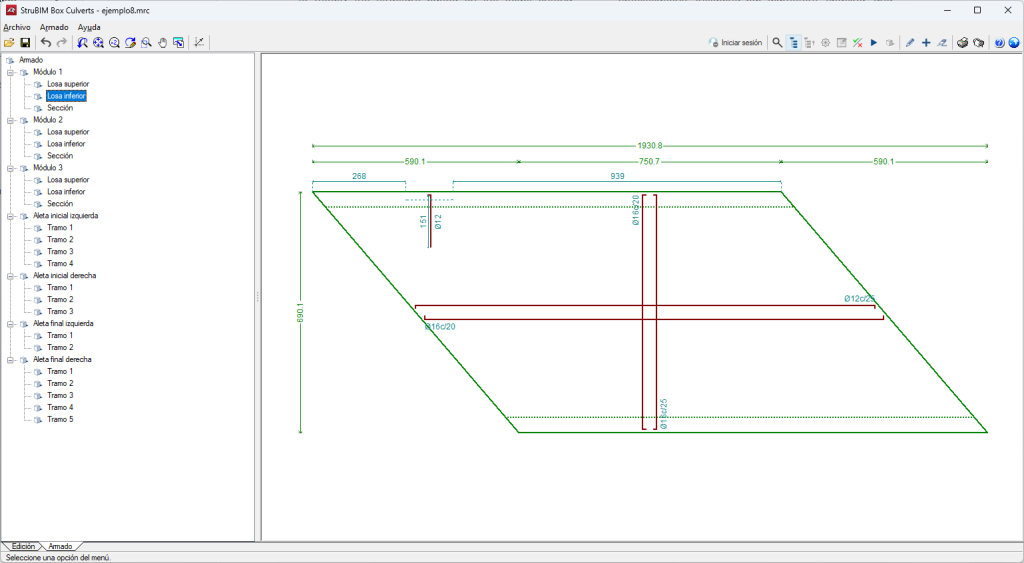
In the Reinforcement tab (bottom left corner of the interface), detailed diagrams of the reinforcement layout are displayed. This section is organised into categories related to its parts (modules and wingwalls). Each category includes subsections for different parts of the frame, showing the reinforcement details for each section.
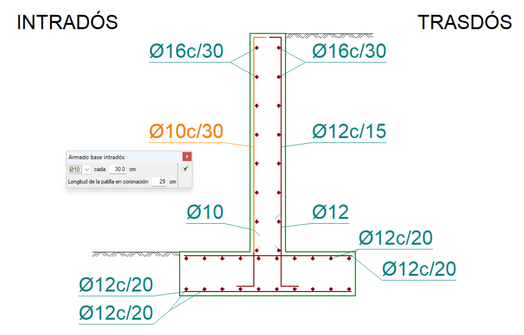
The diagram provides precise reinforcement specifications, including bar diameters, spacing and positions, allowing the reinforcement design to be reviewed and modified as necessary.
To modify the reinforcement, click on the "Edit" option in the "Reinforcement" menu of the toolbar. Then, the desired bar is selected and the properties corresponding to it are displayed in order to make the modifications.
Finally, clicking on the elements in the general categories will redirect users to that particular reinforcement section or span.
Results output
Project reports
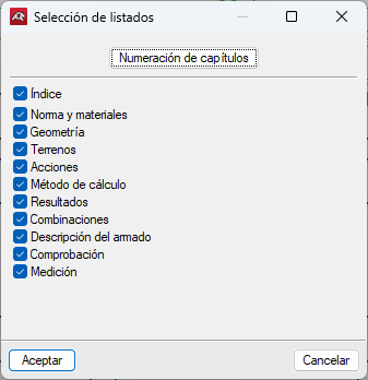
Reports are obtained by accessing the "File" option and then "Reports". The selection window then opens, where users can include or exclude chapters by ticking the corresponding boxes.
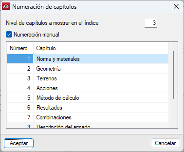
Additionally, the chapters’ numbering can be configured by clicking on the “Chapter numbering” option and selecting the levels to be shown in the index and manually editing their numbers.
The reports can be printed (with an optional preview, page setup, etc.) or HTML, PDF, RTF and TXT files can be generated.
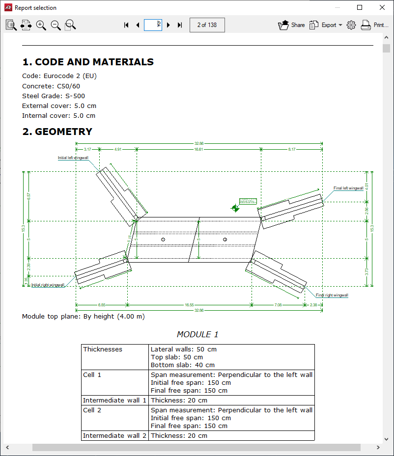
The following reports can be exported from models developed in StruBIM Box Culverts:
- Codes and materials
- Geometry
- Soils
- Loads
- Analysis methods
- Results
- Combinations
- Reinforcement description
- Code checks
- Quantities
Drawings in DWG, DXF or PDF format
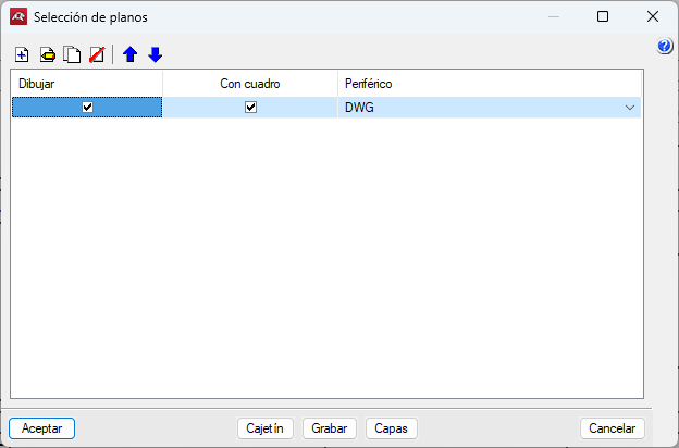
Drawings can be obtained by accessing the "File" option and then "Drawings". Clicking on it opens the “Drawing selection” window.
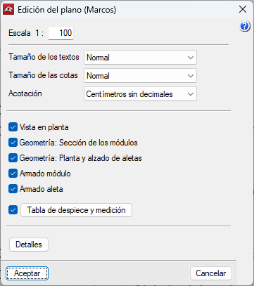
The "Add" button opens the "Drawing editor" window, in which the following operations for generating drawings can be carried out:
- Change the scale of the drawing.
- Graphic notes, such as "Text size", "Dimension size" and the format of dimension units.
- Add one or more drawings to be printed simultaneously with these settings by checking and unchecking the desired ones.
- Include previously imported details and manage them accordingly.
- Once the drawings to be included have been configured and after clicking "Accept", other options can be configured in the drawing selection window, such as including or excluding text boxes and peripherals.
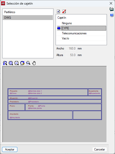
Boxes can also be managed in this menu by clicking on the "Box" option and configuring them in the "Title block selection" window.
The definition of layers can also be carried out in the "Layers" section.
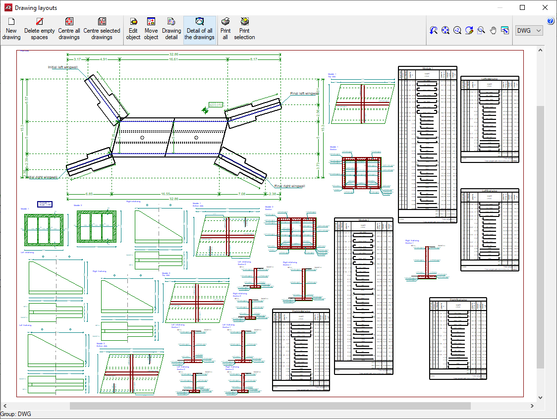
When clicking "Accept", the "Drawing layouts" window will open in the plan selection window. Here, all the generated layouts can be managed with the following options:
- New drawing
Creates a new empty drawing for moving objects into it. - Delete empty spaces
Deletes drawings that do not contain objects. - Centre all drawings
Recovers the original positions of the moved objects, in all drawings. - Centre selected drawings
Recovers the original positions of the moved objects, in the drawings selected below. - Edit object
Moves the texts in the drawing. - Move object
Changes the position of objects within the same drawing, or moves them to a different one. In this case, the objects linked to the selected one are also moved. - Drawing detail
Lets users view an object realistically by clicking on it. Clicking on it again returns it to its original state. - Detail of all the drawings
Allows users to see all objects realistically. - Print all and Print selection
Allows users to print all designs or only the desired ones.
Drawings generated in StruBIM Box Culverts can be exported in different formats such as DWG, DXF or PDF.
glTF file compatible with BIMserver.center
When the project is exported to the BIMserver.center platform, a 3D model is automatically exported in glTF format to integrate the structural model into the Open BIM project, allowing the model to be displayed:
- on the online platform;
- in the BIMserver.center app for iOS and Android;
- in virtual reality and augmented reality;
- in other CYPE programs.
Integration into the BIMserver.center platform
Many of CYPE's programs are connected to the BIMserver.center platform and allow collaborative work to be carried out via the exchange of files in formats based on open standards.
Please note that, to work on BIMserver.center, users can register on the platform free of charge and create a profile.
When accessing a program connected to the platform, the program connects to a project in BIMserver.center. This way, the files of the projects that have been developed collaboratively in BIMserver.center are kept up to date.

| More information: |
|---|
| For further details related to using CYPE software via the BIMserver.center platform, please click on this link. |
Options available in StruBIM Box Culverts
In the "Edit" tab, in the "BIM Model" group of the main toolbar, the required features for using StruBIM Box Culverts together with other BIMserver.center tools can be found.
Importing and updating BIM models
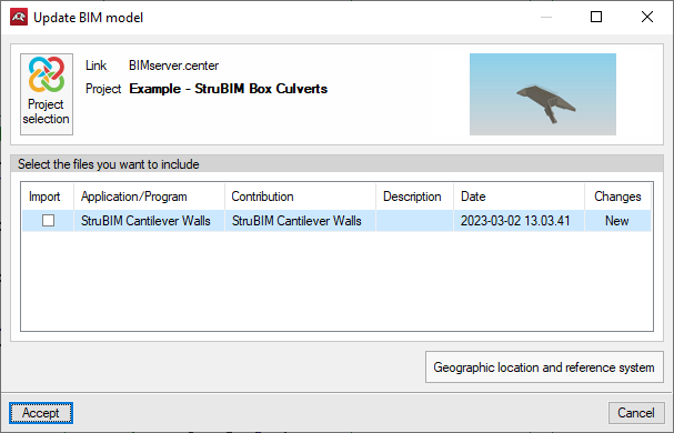
The "Import BIM models" option allows users to update the information contained in the models previously imported into the project or to import new models if desired.
Models are imported according to the defined configuration and users can choose how new, modified and deleted elements of the BIM model are shared.
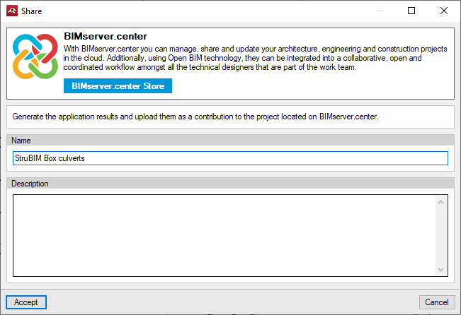
Exporting the BIM model to share it with other users
The information contained in the model developed with StruBIM Box Culverts can be exported to BIMserver.center using the "Generate the application results and upload them as a contribution to the project located on BIMserver.center" option.
During the export process, users can establish information related to the identification of the files to be exported, the location of the local copies that are automatically generated and the types of files that are generated.