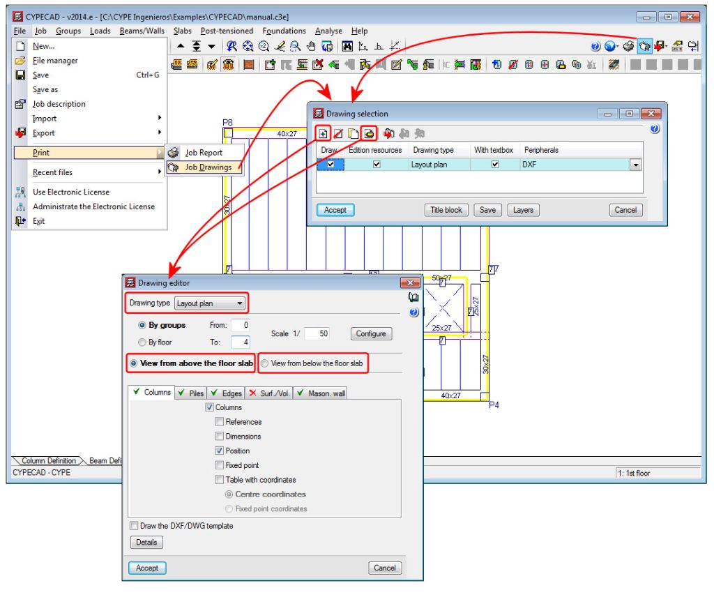
The generation process of the “Detailing of columns” plan has been optimised internally, substantially reducing the time required to create it.
Cronologia degli aggiornamenti
- CYPECAD
- Cronologia degli aggiornamenti

CYPECAD
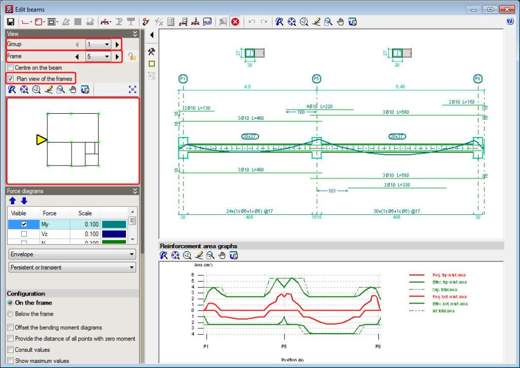
A plan view of the current floor is displayed in the “View” section on the left side menu of the advanced beam editor. Users can use the view to select a different frame to edit by clicking on the frame with the left mouse button.
Please recall it has been possible, since previous versions, to change groups and frames by selecting them in the drop-down menus next to the “Group” and “Frame” texts that appear in the same “View” section.
CYPECAD reduces the inertia of the concrete elements in seismic analyses and only for seismic loadcases, when the codes indicated below are applied. The codes that are implemented in the program which include seismic analyses using cracked inertias are:
- CIRSOC 103-2005 (Argentina)
Normas Argentinas para Construcción Sismorresistente. Parte II: Construcciones de Hormigón Armado. - CSCR 2010 (Costa Rica)
Código Sismo de Costa Rica 2010. - NEC-11 (Ecuador)
Norma ecuatoriana de la construcción. Capítulo 2.- Peligro sísmico y requisitos de diseño. - R-001 2011 (Dominican Republic)
Reglamento para el Análisis y Diseño Sísmico de Estructuras
Code implementation and improvements in its application. NCh433.Of1996 Mod.2009 (Dºnº61. de 2011) (Chile)
Norma Chilena Oficial. Diseño Sísmico de Edificios.
This code was already implemented as of previous versions in CYPECAD and Metal 3D for the dynamic analysis method (modal spectral) – including the modifications of Decree nº61 (V. and U.) of 2011.
The 2014.e version of CYPECAD also includes a static analysis method (equivalent lateral force) for this code. Users can select the analysis method (dynamic or static) using the Analysis method option within the dialogue box in which seismic action is defined.
CYPECAD has carried out the correction due to base shear using the dynamic analysis method (spectral modal) since the 2013.a version.
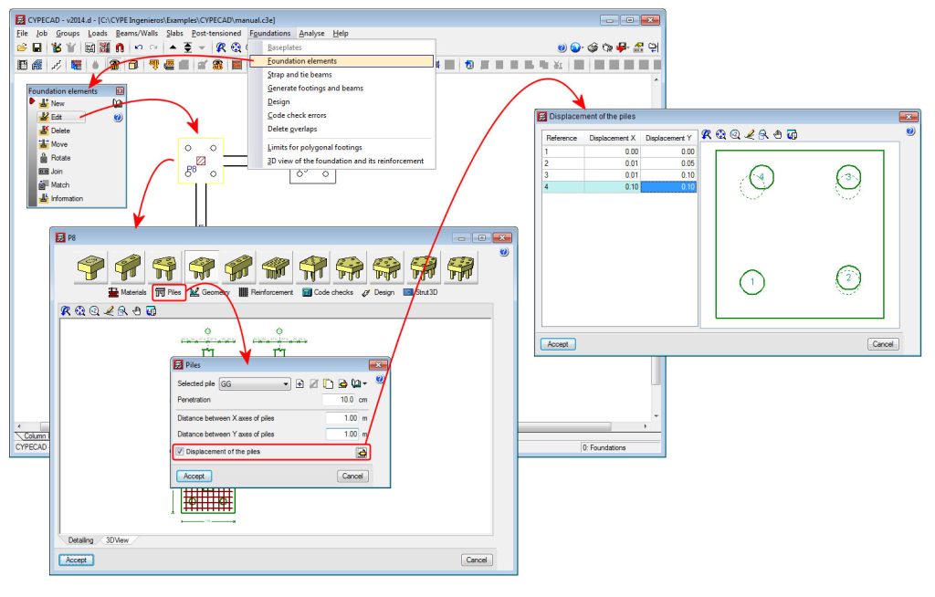
A new option, “Displacement of the piles” has been implemented in the “Piles” dialogue box (see image). This option allows users to introduce a displacement value for each pile of the pile cap with respect to its original position. The displacement is introduced using the X and Y components of the local axes of the pile cap.
This option has been implemented so a change in the position of the piles during the execution phase of the job can be contemplated. If this occurs, the designer can introduce the displacement the piles have undergone with respect to those of the project, and by selecting the check option, can check whether or not the pile cap continues to meet its requirements.
Therefore, the effect of the displacements of the piles that are introduced using this option, are only used to check the pile cap. The design and drawings that are generated are all carried out bearing in mind the original position of the piles.
Implementation, in Strut3D, of the following concrete codes: ABNT NBR 6118 2007 (Brazil), ABNT NBR 6118 Projeto Junho 2013 (Brazil) and Eurocode 2 (EU, France and Portugal)
The tool, Strut3D, was implemented in the 2013.e version. This tool allows users (in CYPECAD and Metal 3D – using the Pile caps module – and in Foundation elements) to check pile caps using a general analysis methodology whereby the D regions of the reinforced concrete are analysed using a strut and tie method. This tool was only available for use with the Spanish EHE-08 concrete code.
In the 2014.b version, more codes could be used with Strut3D: ACI 318M-08 (USA), Nch430.Of2008 (Chile), NTE E.060:2009 (Peru) and NSR-10 (Columbia).
With the 2014.d version, Stut3D has been implemented to be used with more concrete codes:
- ABNT NBR 6118 2007 (Brazil)
Projeto de estruturas de concreto – Procedimento
- ABNT NBR 6118 Projeto Junho
Projeto de estructuras de concreto – Procedimento (project code that will substitute the code that is currently in force; ABNT NBR 6118 2007)
- Eurocode 2 (EU)
Design of concrete structures. EN 1992-1-1:2004/AC 2008
- Eurocode 2 (France)
Calcul des structures en béton. NF EN 1992-1-1:2005/NA: Mars 2007
- Eurocode 2 (Portugal)
Projecto de estruturas de betão. NP EN 1992-1-1:2010/NA
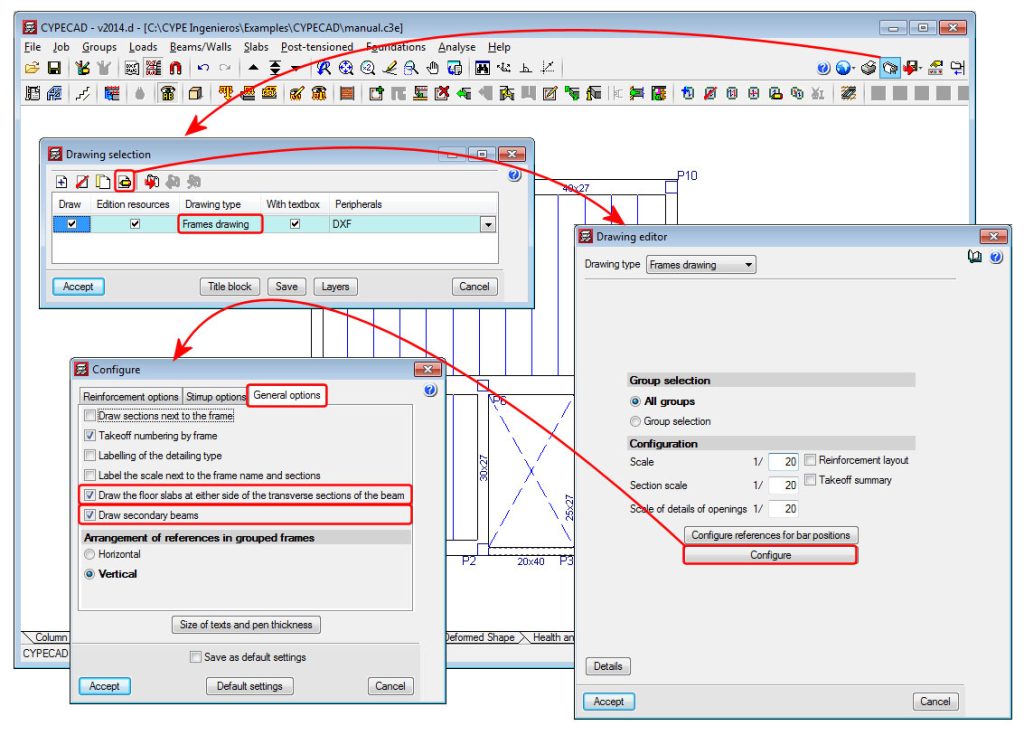
The 2014.d version of CYPECAP includes the option to “Draw secondary beams” in the configuration dialogue box for the frames drawing (see image). This option draws secondary beams (or not draw them if left inactivated) in the longitudinal section of the frames represented in the frames drawings. For CYPECAD, a secondary beam is that which divides which the longitudinal reinforcement of the beam.
This option will only be available with jobs analysed in accordance with a concrete code or seismic code (if a seismic analysis is being carried out) available for use with the advanced beam editor.
A new option has been included in the 2014.d version of CYPECAD: “Draw the floor slabs at either side of the transverse sections of the beam”. This option is located in the configuration dialogue box for the frames drawing (see image). By activating this option, the floor slab will be displayed in the transverse sections of the frames in the frames drawing.
This option is only available with jobs analysed in accordance with a concrete code or seismic code (if a seismic analysis is being carried out) available for use with the advanced beam editor.
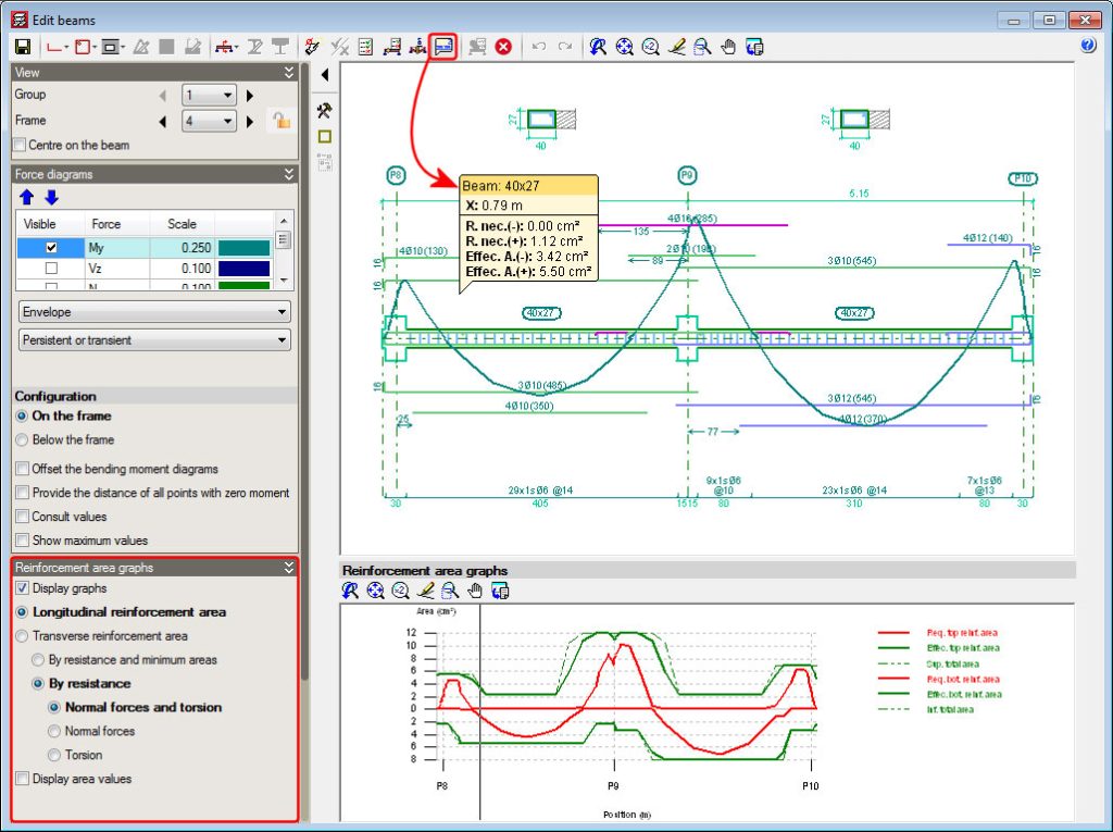
A new option has been implemented: “Consult the required and effective areas” (![]() button) in the advanced beam editor of CYPECAD. When this option is selected, the program displays the required and effective areas of the reinforcement of the frame at the point of the longitudinal section where the cursor is positioned.
button) in the advanced beam editor of CYPECAD. When this option is selected, the program displays the required and effective areas of the reinforcement of the frame at the point of the longitudinal section where the cursor is positioned.
The information displayed moves with the cursor along the frame and displays the corresponding areas at the point where the cursor is positioned.
The data that is visualised on-screen corresponds to the type of reinforcement selected in the “Reinforcement area graphs” section in the left lateral menu of the advanced beam editor (longitudinal reinforcement area, transverse reinforcement area, resistance reinforcement and minimum steel areas...).
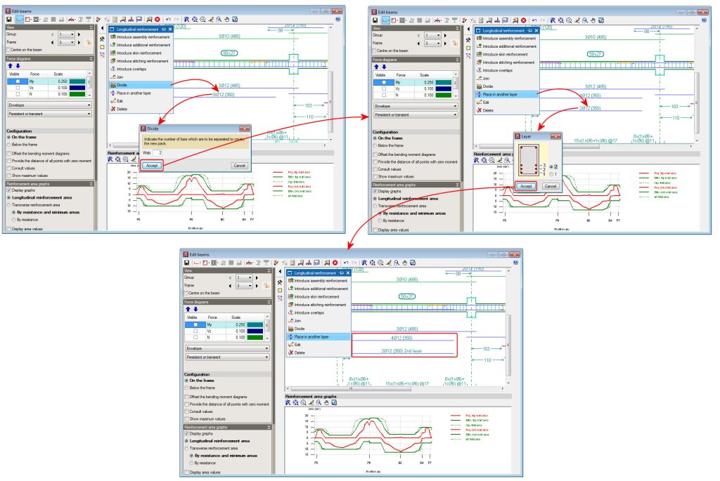
A new option; Divide, has been implemented in the longitudinal reinforcement edition box of CYPECAD’s advanced beam editor. This option allows users to divide a pack of bars, in such a way that the number of bars indicated by users then becomes part of the other pack. By implementing this option, the one or two packs remaining after the division can be changed to other reinforcement layers.
In previous versions, to change bars belonging to a bar pack from one layer to another, user had to carry out two steps: reduce the number of bars of the packet and create another packet with the same number of bars that were removed (as well as having to indicate the same diameter, position and bar length). This procedure was not only a longer process but also increased the possibility of there being errors in the modifications.
Dropped rectangular beams with variable sections can now be introduced in jobs analysed in accordance with a concrete code or seismic code (if a seismic analysis is being carried out) available for use with the advanced beam editor .
This possibility was already available with Continuous beams program. Now in CYPECAD, within the beam introduction dialogue box, a new type of beam has been added for which the program requests the width, initial depth and final depth.

