Update history​

CYPECAD

Implementation. NTC-2023 (Mexico CDMX)

Norma Técnica Complementaria para Diseño y Construcción de Estructuras de Acero.

Implemented in:

  • CYPECAD and CYPE 3D for designing and checking rolled and reinforced steel sections.
  • CYPE Connect and StruBIM Steel for checking bolted and welded steel connections.

Implementation. NTC-2023 (Mexico CDMX)

"Norma Técnica Complementaria para el Diseño por Sismo".

Implemented in CYPECAD and CYPE 3D.

Implementation. NBDS-2023 (Bolivia)

"Norma Boliviana de Diseño Sísmico".

Implemented in CYPECAD and CYPE 3D.

Implementation. NTC-2023 (Mexico CDMX)

"Norma Técnica Complementaria para Diseño por Viento".

Implemented in CYPECAD.

Update notification available

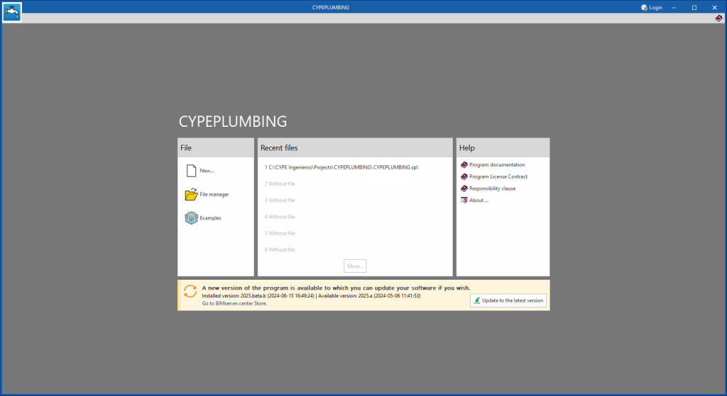
As of version 2025.b, applications now display a warning message in their initial window when a new update is available. This message provides information about the "installed version" and the "available version", together with a direct link to the Store page of the BIMserver.center web platform.

Clicking on the “Upgrade to the latest version” button automatically starts the download and installation process of the application. This feature ensures that the most current version of the program is always being used, thus benefiting from the latest improvements.

This method replaces the automatic notification and update process of a new version in the BIMserver.center programs available in previous versions.

Link to the BIMserver.center Store

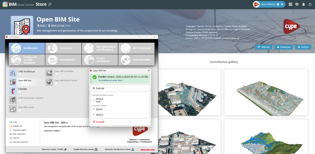
In the configuration panel for each application, a direct link to its page in the BIMserver.center web store has been included.

By clicking on the “Go to BIMserver.center Store” button, users are redirected directly to the corresponding page in the Store, where they can learn more about the application, view its features, read reviews from other users and see examples of real contributions.

This feature provides easy access to additional resources and support, enhancing the user experience by providing quick and easy access to all relevant information about the applications.

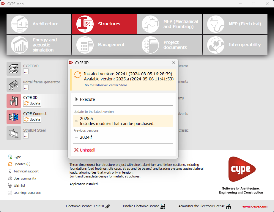
Information about the license model

An information message has been incorporated into the installation button of the applications so that, before proceeding with the installation, users can identify which applications are free to use (free of charge) and which require licensing permissions (including paid modules).

This enhancement improves the user experience by providing clarity and transparency on the options available to the user based on their license model.

Installing background apps

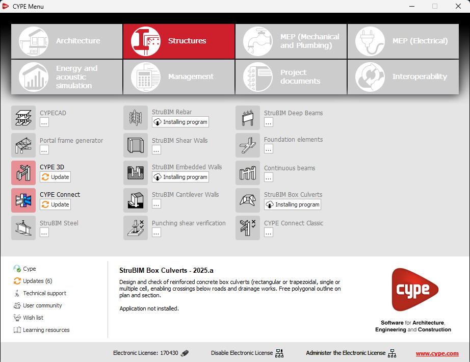
In the new 2025.b version of CYPE Menu, the background installation feature has been added. Users can now continue working on other tasks while applications are automatically installed in the background.

During the background installation process, the “Installing program” message is displayed next to the applications button in the main CYPE Menu window. Once completed, the message disappears and the application can be run.

This feature is designed to make applications easier to use and manage, improving productivity and the overall experience by minimising waiting time and interruptions during the installation of new applications or upgrades.

Other improvements and corrections

CYPECAD version 2024.b includes the following program improvements and corrections for some specific cases:

  • The design of columns has been improved. Now, columns whose lower floors have been defined with "Reinforced concrete", "Steel", "Timber" or "Mixed section" materials and whose upper floors have been defined with "Generic" materials are designed.
  • The entry of predefined loads has been improved. Selecting a predefined load now displays the values it has been defined with.
  • The drawing of beams has been improved. If a beam end has a defined "Partial fixity", the same symbol used for unfilled pinned ends is shown.
  • An error that occurred when inserting block walls has been fixed. This error could occur when inserting these walls after a concrete wall.
  • An error that occurred when designing beams has been fixed. This error could occur when the number of bars in the reinforcement assembly was so large that they overlapped each other.
  • An error that could occur in "Flat/Waffle slabs > Recover reinforcement copy of all groups" has been fixed. This error could occur very rarely in floors where waffle slabs and flat slabs were defined with the longitudinal reinforcement of one of the slab types rotated by 90° compared to the other.
  • An error regarding the discretisation of walls has been fixed. In the case of certain incorrect connections of walls to columns, a message is displayed in this process. It is currently only possible to display the message when analysing the job, the message cannot be displayed when using "Check the geometry of all groups". This error is caused by entering a column with a support difference of -0.1m, and connecting a wall to this column without assigning it a plane defined in "Sloped floor slabs/Elevation Changes" with the same elevation change. In future versions of the program, there are plans to warn of this incident before starting the design process.
  • An error that occurred during the column design process has been fixed. This error could occur in some cases when columns with no external connection originated in a wall footing with soil-structure interaction.
  • The drawing of rectangular-shaped stirrups in circular columns has been improved. Previously, the drawings of these stirrups, shown in the column table, were transformed into square-shaped stirrups.
  • An error that could occur when entering building sections in cases where there was a flight of stairs with only one step has been fixed.
  • An error that occurred when entering building sections in some cases when there were staircases defined with a final horizontal flight on the last straight flight has been fixed.
  • An error that could occur when designing staircases where a straight flight with a step had been defined in the staircase when the riser was less than or equal to the edge of the slab has been solved.
  • An error has been fixed when importing a job from an IFC. This error could occur if there were columns in the IFC but none of them were defined correctly.
  • The import of jobs from an IFC has been improved. From version 2024.d, steel columns defined in the IFC could not be imported due to a program error that was caused by fixing another error.
  • The drawing of the column references has been improved. For a column with "Support Elevation Change", the value was shown in metres rounded to multiples of 10 cm. Now the value entered (without being rounded) is shown according to the units defined in "Levels" in "General options > General drawing options".
  • Entering integrated 3D structure connections has been improved by allowing connections to be inserted at least 5 cm apart from the nearest one.
  • The export of steel columns to Open BIM Quantities has been improved. If there were several columns with the same characteristics on a floor, they were exported with their length multiplied by the number of columns.
  • An error that used to occur when analysing the deflection in the design of beam frames has been fixed. This error would rarely occur in the case of spans between columns with intermediate beam intersections.
  • An error that occurred when reinforcing flat slabs or waffle slabs has been fixed. This error could occur if hollow core slab floors without a compression layer or timber joist floors had been inserted on the same floor.
  • An error has been fixed when entering concrete walls with the "Shear wall" option activated. This error occurred if a new panel was generated when entering the wall.
  • An error that occurred in the analysis process if "Design joints" had been checked when the necessary permissions for designing the joints were not available, has been fixed.
  • An error that occurred in the "3D view of the building" option after removing tangential stress reinforcement has been fixed.
  • An error that occurred when selecting a job with the "Check fire resistance" option unchecked, while one of the "Fire resistance" options is being carried out in a job where "Check fire resistance" is checked, has been fixed.
  • An error that occurred with "Undo" in "Column Definition" if a floor "under foundation" had been added in the job has been fixed.
  • An error that occurred in "Envelopes > Deformed shape" has been fixed. The error occurred in the "Consult" option when selecting another loadcase or combination other than the one being displayed.
  • An error that occurred in "Drawings" when clicking on the "Add" button has been fixed. This error could occur if integrated 3D structures from CYPE 3D with views associated with levels had been imported into the job. The error did not occur if the imported integrated 3D structure was edited after importing.
  • The drawing of plane stress walls has been improved. If the wall was defined with different values for "Thickness to the left" and "Thickness to the right", the reinforcement was not centred.
  • The export of job elements to an IFC file has been improved. A distinction is now made between foundation beams, tie beams and centring beams. Foundation beams are exported as "IfcBeam". Centring and tie beams are exported as "IfcFooting".
  • An error that occurred in "3D view with details" has been fixed. This error occurred in rare cases due to tangential stress reinforcement.
  • The reinforcement report of beams has been improved. The "Include reinforcement bars and force diagrams" option has been split into "Reinforcement bars" and "Force diagrams".
  • The design and checking of foundation elements has been improved. The dimensioning and checking of the foundation, in certain cases where long strip footings had been defined, could not be completed because the analysis result was a mechanism. In the current version, mechanisms are no longer produced in these cases.
  • An error that occurred in the beam portal frame editor when changing the stirrup template has been fixed. This error could occur if the number of longitudinal bars in the top or bottom reinforcement did not match those in the template.
  • The beam portal frame drawing has been improved. If the covers of all the frames in a floor are the same, they are shown in the material schedule of the floor. If they are not, they are shown below the portal frame reference.
  • An error that occurred in the design of joist floor slabs has been fixed. This error could occur in inclined joist floor slab alignments with 0 fixity coefficients.
  • The editing of beam frames has been improved. Hardware acceleration is now used in the drawing of frames, which means that in many cases, such as frames with a large number of spans, the speed of the drawing is improved.
  • The drawing of the start of columns in footings has been improved. If the column has a different cover to the general one, this was not taken into account when generating the start detailing.
  • An error that occurred in "BIMserver.center>Share" with the "Quantities" option selected has been fixed. This error occurred for jobs where no floor plans had been defined.
  • The export of 135° and 180° stirrup branches has been improved. Previously, one of the hooks protruded in the opposite direction to the other.
  • The drawing of moments and shear values of joist floors entered "By geometrical properties" has been improved. As of version 2025.b, these values are always drawn in the direction of the joists, regardless of whether "Horizontal" has been selected in the "Label sense" option.
  • An error that occurred in the design of timber or steel joists in some cases where continuity of joists has been defined between two panels that were in contact in one area and with another panel between them in another area, has been fixed.
  • The entry of elements in "Editing resources" in the beam frame editor has been improved. Now, portal frame geometry can be snapped.
  • The 3D view and export of beam stirrups has been improved. Now, "Closed branch" type branches are considered. Furthermore, in some cases, the stirrup hooks were generated in the opposite direction to the correct one.
  • The 3D view and export of the reinforcement of plane stress walls has been improved. In several cases, in this type of wall, the bars to be displayed and exported were not generated correctly.
  • An error has been fixed when generating column detailing drawings. This error could occur if more than one column detailing drawing had been defined.

  • The display of non-orthogonal joist intersections in the 3D view has been improved. This display had been incorrect since version 2025.a due to changes made to solve other issues.

  • The display of tie beam and centring beam intersections with tapered footings in the 3D view has been improved. This display had been incorrect since version 2025.a due to changes made to solve other issues.

  • The beam reinforcement report has been improved. If the "Forces" option is selected, the forces of steel beam frames and timber beam frames are included.

Fire resistance checks with manufacturer's intumescent paints

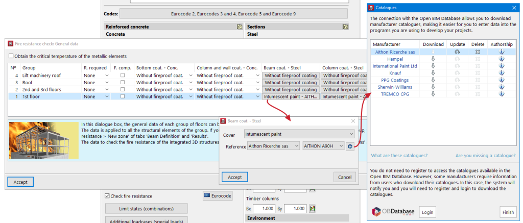
In CYPECAD version 2025.b, intumescent paints from manufacturers' catalogues have been incorporated.

In "Job > General data > Check fire resistance", users can select the type of protective coating for the steel beams and columns on the individual floors of the job. By selecting "Intumescent paint", the available catalogues can be used.

The thickness of intumescent paint required to protect each of the steel elements is obtained from the selected catalogue, based on the calculated critical temperature, the form factor, the number of exposed faces and the type of structural element (column or beam).

The form factor is calculated from the exposed section surface and its area. For columns, the entire surface is considered to be exposed. For beams, their exposed area is obtained by considering the position in the floor slab.

Checks for PEIKKO punching shear studs according to EOTA

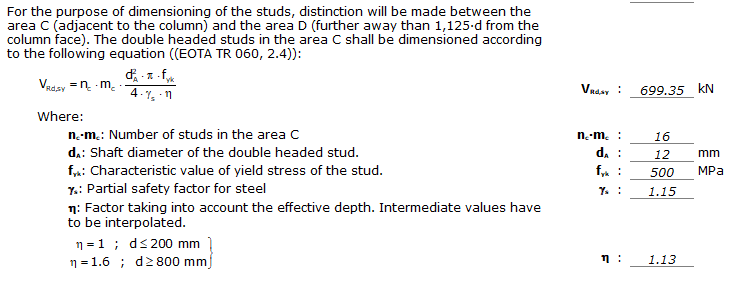
As of CYPECAD version 2025.b, the punching shear check according to the specifications of EOTA TR-060 (European Organisation for Technical Assessment) is implemented for punching shear studs from PEIKKO.

This implementation involves a modification of the checks carried out both on the critical perimeter and on the outer perimeter of the punching shear reinforcement when using bolts from manufacturers with ETA (European Technical Assessment) documents, as is the case with PEIKKO punching shear studs, which optimises their use and their resistance capacity together with the slab.

Specific slab covers for each panel

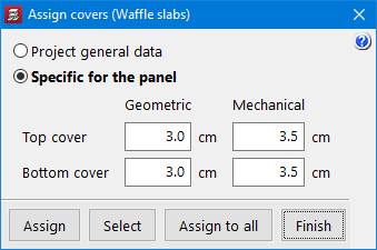
In CYPECAD version 2025.b, the possibility of assigning covers to panels other than those entered in the general data of the job has been implemented.

To do this, in "Beam Definition > Panels > Assign covers" users can select the "Specific for the panel" option.

The option has been implemented for all types of floor panels that can have covers: waffle slabs, flat slabs, joist floor slabs, composite slabs and hollow core slabs.

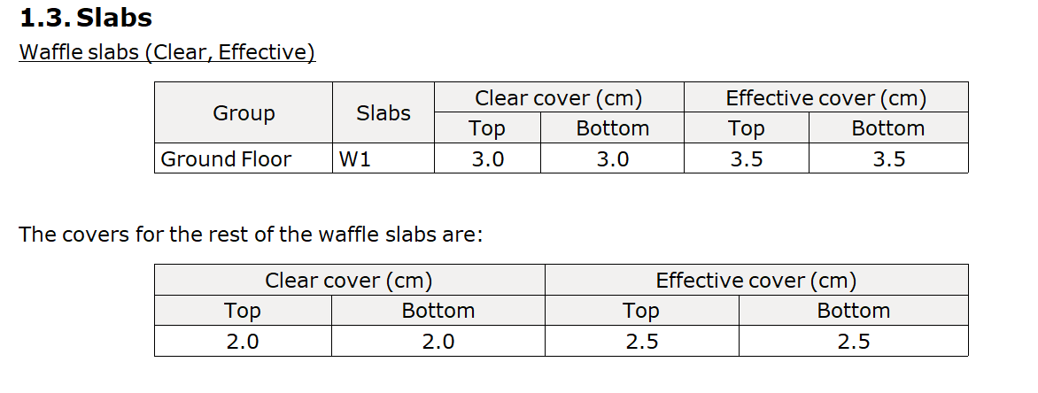
In the job data report, in the "Covers" section, the different covers defined for the panels are shown, if applicable.