
Introduction
CYPECAD is a BIM program for designing, analysing and designing structures for building and civil works in accordance with different standards.
As a result, CYPECAD generates a multitude of detailed reports, as well as the construction plans necessary to complete the project documents.
It is also possible to export measurements and bill of quantities, as well as the project's IFC.
Introduction: examples and creating new jobs
When starting the program and creating a new job, the program offers different possibilities, such as linking to BIMserver.center, creating an empty project to start the project from scratch, importing projects from CYPE 3D, or generating geometries from DXF/DWG files or models saved in IFC files.
Later, the program allows the user to configure the general data for the project and then access the main working interface.
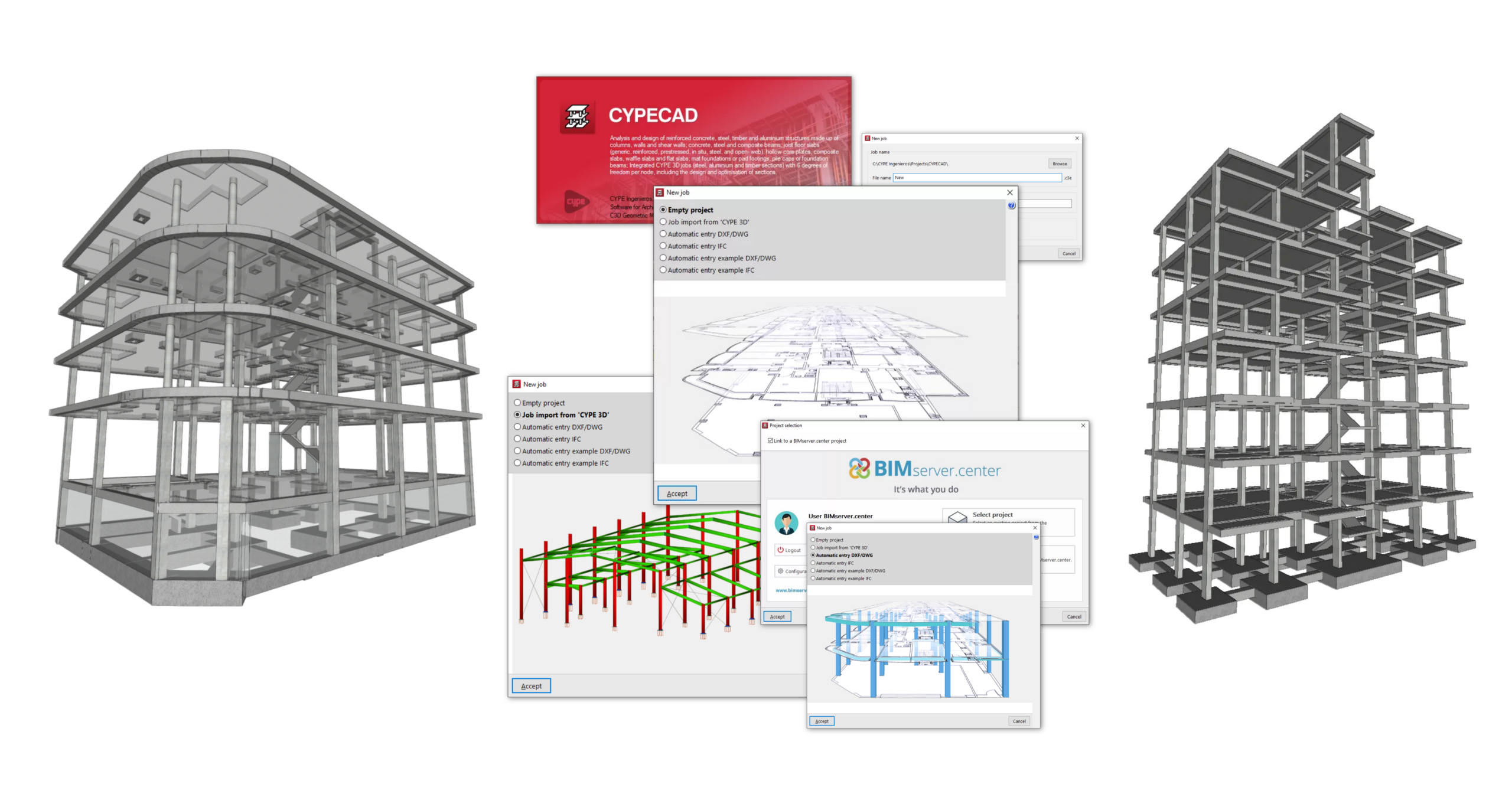
The following link provides detailed information on the options available in the initial process of creating new jobs, as well as a gallery of examples of structural models developed using the program.
General data configuration
The "General data" settings for the project are configured when the project is created or, subsequently, using the specific option accessible from the different tabs in the program.
This is where aspects such as the following are defined:
- the standard to be verified;
- the materials used in the construction;
- the loadcases and combinations of loadcases, including data relating to seismic action and wind action;
- as well as the adjustment of other configuration parameters for the analysis, such as the reinforcement tables used or the design options for the different elements in the job.
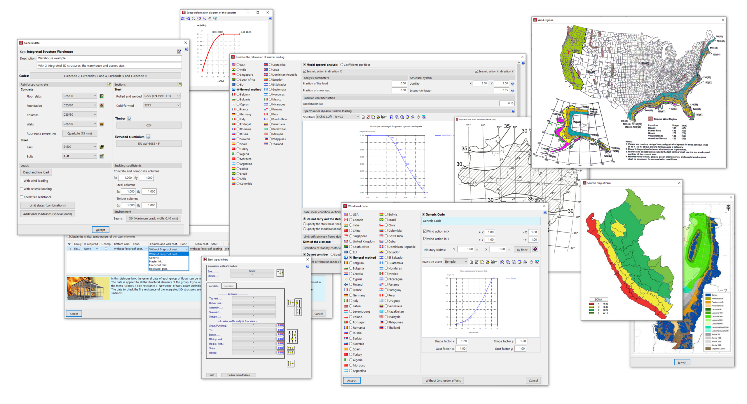
The following link provides detailed information on the options that appear in the "General data" configuration panel:
Defining floors and groups of floors and inserting columns, shear walls, and starts
The "Column input" tab is the first tab available when you open the program. The following aspects of the project are configured here:
- The model's floor and group of floors layout is defined, enabling the subsequent insertion of structural elements between floors or on each floor.
- The structural elements available in this tab are inserted and/or edited: columns of different materials (concrete, steel, wood, mixed or generic), shear walls (vertical reinforced concrete elements with a section formed by one or more segments that are discretised into finite elements) and starts (or column foot sections where it is possible to enter loads or define a point for the subsequent insertion of foundation elements).
Furthermore, from this tab, it is also possible to access the general data for the project.
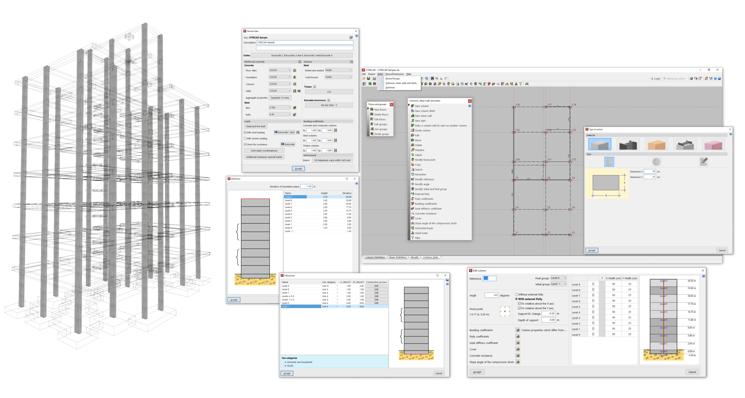
Subsequently, the user must complete and analyse the structure model in the "Beam Input" tab.
The following link provides detailed information on the options that appear in the "Column input" tab:
Inserting beams, walls, slabs, foundation elements and special elements, and structural analysis
After defining the floors and columns in the "Column input" tab, the user continues working in the "Beam input" tab, where the model is completed with elements such as the following:
- the beams;
- the floors and foundation slabs;
- the walls;
- the stairs and ramps;
- the integrated 3D structures;
- and/or the foundation elements.
After completing the model, the analysis ofthe job is also carried out in this tab.
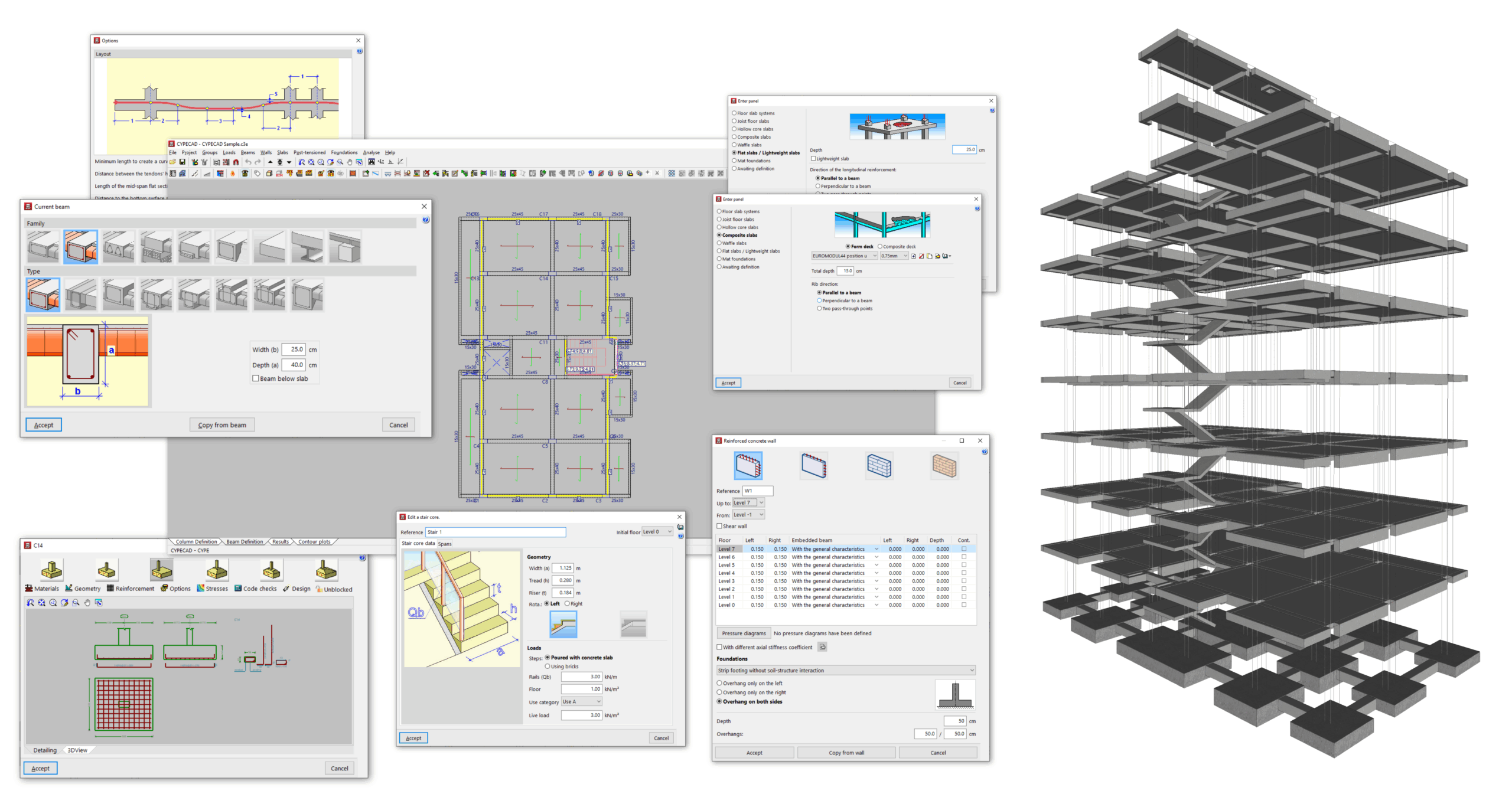
The following link provides detailed information on the options that appear in the "Beam input" tab:
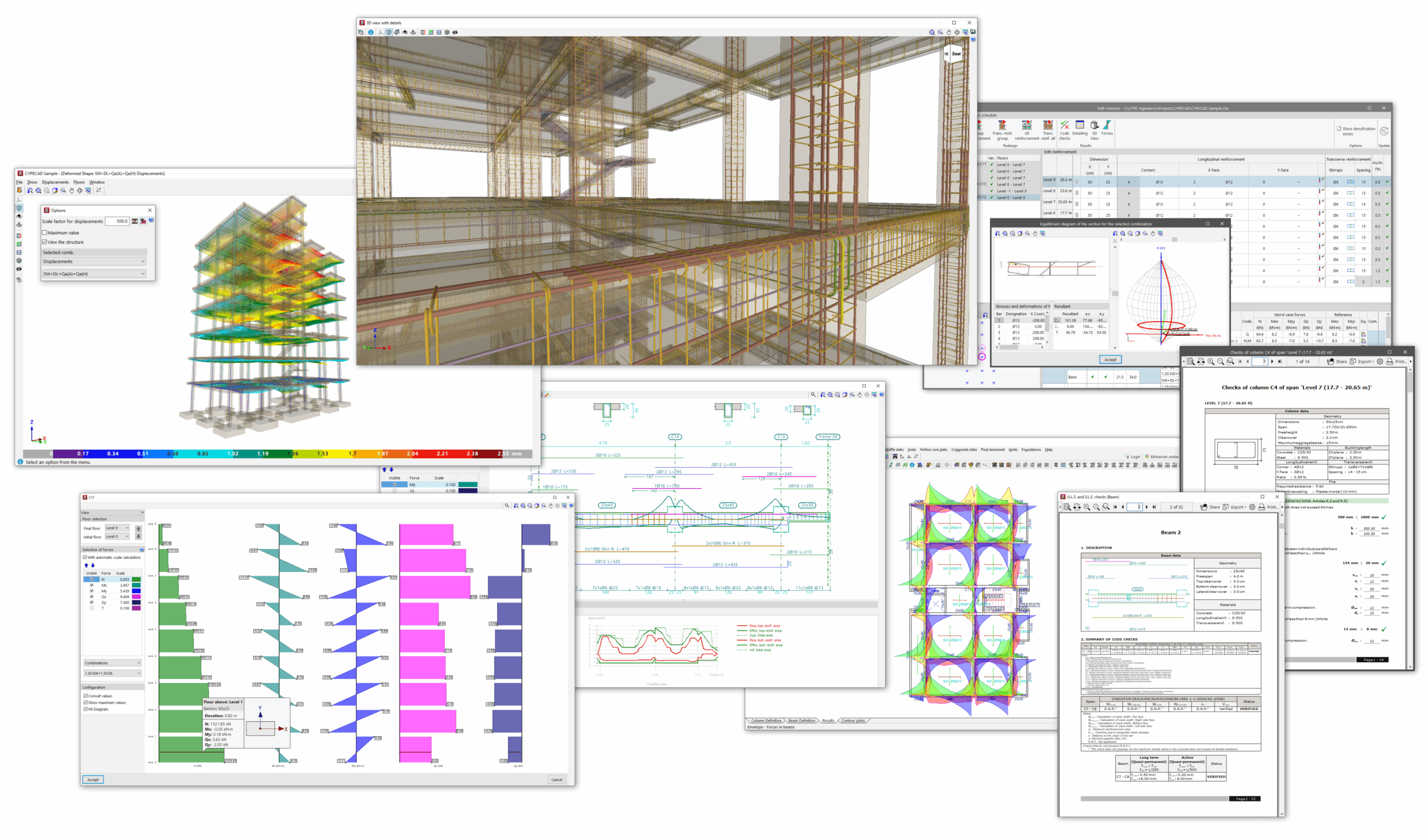
Viewing analysis results and editing elements
Once the analysis of the job has been carried out in the "Beam input" tab, you can access the "Results" tab, where the results obtained for the different elements of the model are collected and can be consulted, such as the following:
- the forces, displacements and reinforcement of beams, slabs and floor slabs;
- the forces, displacements and reinforcement of columns, shear walls and walls;
- the geometry and calculated reinforcement for foundation elements;
- the analytical model and deformation of the structure;
- and the reports of checks carried out on elements such as columns, beams or foundation elements;
In addition, the program allows for the adjustment and editing of elements such as columns, walls, beams, or slabs through specific options and editors.
The following link provides detailed information on the options offered by the program under the "Results" tab:
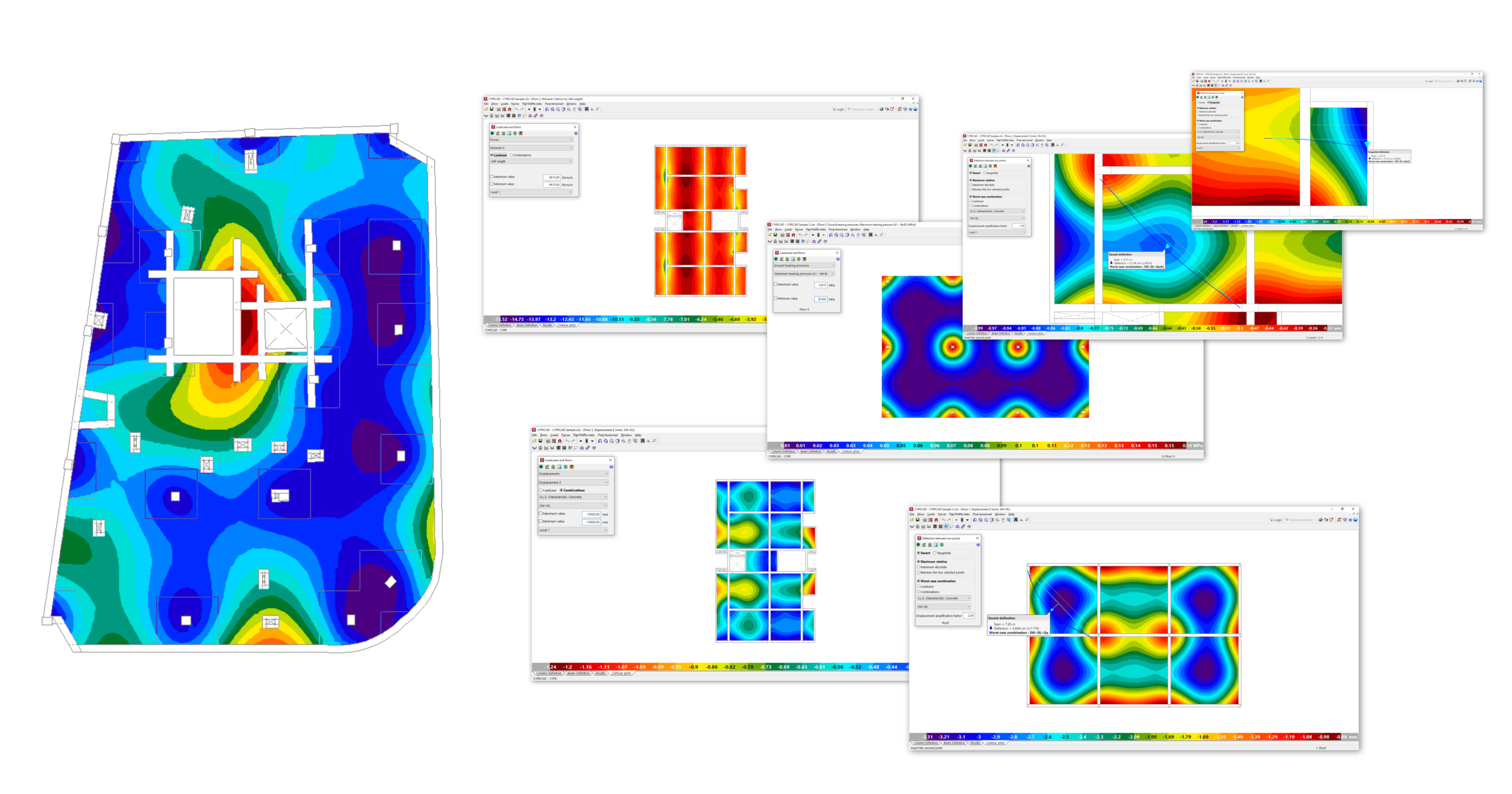
Options in the "Contour plots" tab
The "Contour plots" tab provides a specific environment for viewing the analysis results for slabs and two-way slabs in the form of contour plot diagrams of forces, displacements and quantities.
You can also check the arrow between two points or the average value of different magnitudes between two points or within a band.
The following link provides detailed information on the options offered by the program under the "Contour plots" tab:
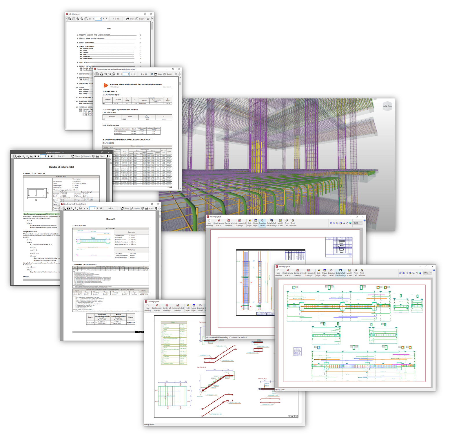
Printing documents and exporting data
After analysing the job, consulting the results obtained and making the corresponding adjustments in the "Results" tab, the program allows you to obtain the following documents:
- analysis reports, including checks carried out in accordance with different standards for each of the elements, which can be printed directly or exported to HTML, DOCX, PDF, RTF or TXT formats;
- the drawings of the job in DWG, DXF or PDF format;
- and the quantities and cost estimates of the structural elements, which can be exported directly to Arquimedes or to files in FIEBDC-3 format to be processed by other quantity surveying and cost estimation programs;
- in addition, when exporting measurements and estimates to Arquimedes, the rest of the documents linked to the CYPE Cost Databse can be generated, such as the specifications, the ten-year maintenance assessment, the health and safety study, waste management, life cycle analysis and the building use and maintenance manual.
Finally, the program will allow you to share the information generated by the program with a BIM project on the BIMserver.center platform using, among other formats, IFC files. This way, it can be used by other apps linked to the project.
The following link provides detailed information on the options offered by the program for printing documents and exporting the data obtained after the analysis:
CYPECAD features
The following link provides further information on the general features of CYPECAD, including:
- the structural elements analysed in the program,
- the types of analysis performed (including seismic analysis, fire resistance verification and results analysis),
- and information about the documents obtained and data export, the standards included and the available versions of the program:
Table of contents
Complete your tour of CYPECAD by exploring the other available sections:
- Introduction
- Introduction and creating new jobs
- General data configuration
- Defining floors and groups of floors and inserting columns, shear walls and starts ("Column input" tab)
- Inserting beams, walls, floor slabs, foundation elements and special elements, and structural analysis (the "Beam Input" tab):
- Checking analysis results and editing elements (the "Results" tab):
- Options on the "Contour plots" tab
- Printing documents and exporting data
- More information:
- General features of CYPECAD


