Analysis and code checking of connections
Once the connection has been modelled, the analysis and checking can be carried out. The "Analysis" tab has the following options for this purpose:
Generate from the BIM model
This option will be available when the job has been created from a BIM model with forces. The load cases and loads of the sections involved in the connection can be generated.
To do this, the load combinations to be read can be filtered. Not all load combinations have significant values, so it may be advisable to filter the number of combinations to be imported. By default, a filter is shown for each of the 6 forces. The combinations in which the force exceeds the maximum value by a certain percentage, both positive and negative, will be read for each force. Furthermore, a minimum value can be set to determine whether the combinations should be read.

With this option, loads can also be imported for the rotational stiffness analysis. In addition to the loads, the elastic lengths of the bars of the structural model are also imported; these lengths are necessary for the correct classification of the connection. There are five options for importing load cases according to forces:
- Maximum moments, with simultaneous forces
Imports the load cases with the largest moments "My" or "Mz", with a positive or negative sign, in addition to the other simultaneous forces. - Maximum moments, without the other forces
Only imports the "My" and "Mz" values from load cases with maximum moments. - Maximum moments by plane, with simultaneous forces
Imports load cases with maximum moments and their simultaneous forces per plane i.e. creates load cases with forces per plane (XY and XZ). - All
Imports all load cases. - None
No load cases are imported.
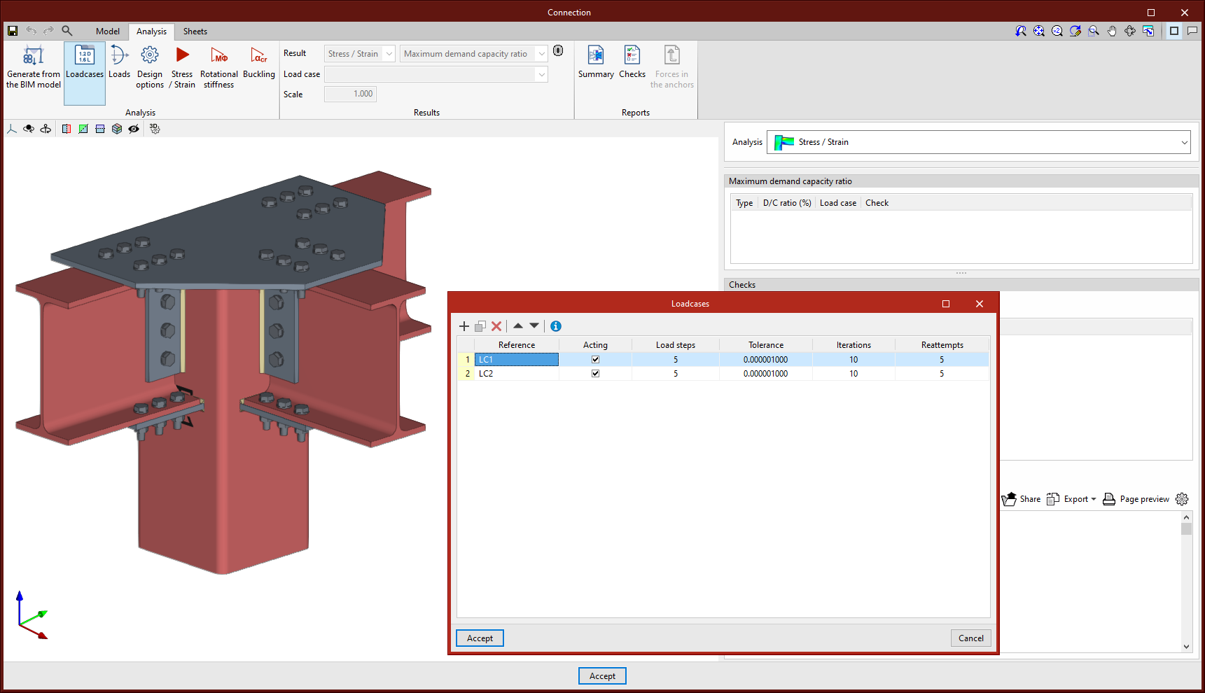
Loadcases
This option can be used for defining the load cases to be considered in the connection analysis. These load cases can be generated from the BIM model or configured manually by the user. The following parameters are defined for each load case:
- Number of load steps.
- Allowable tolerance to consider the convergence has been reached.
- Maximum number of iterations in each load step.
- Maximum number of reattempts.
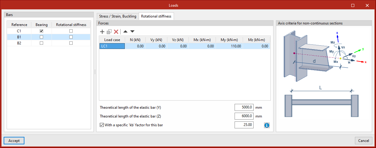
Loads
This tool opens the "Loads" dialogue box, where the loads acting on each section for each load case are defined. Tables can be copied and pasted directly from a spreadsheet. One of the sections must be the load-bearing section.
In addition to the loads, the position of the force application point can be defined for each section. This distance will also be read in the BIM model, provided that the structure has been analysed considering the finite dimension of the nodes.
Furthermore, users can also select the bars from which the rotational stiffness of the connection is to be analysed. In the central part of this window, two tabs appear to define the load tables per load case. The "Rotational stiffness" tab requires a list of loads, the lengths of the elastic bar in the structural model (used to establish the limit stiffnesses of rigid or pinned connections) and the kb factor.
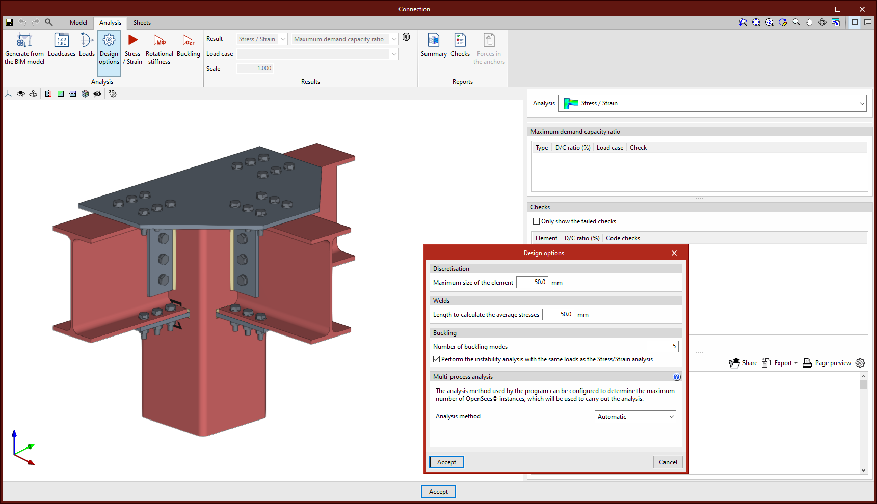
Design options
Here, users can define the following:
- The maximum discretisation size of elements.
- The length to calculate the average weld stresses.
- The multi-process analysis method of the OpenSees© analysis engine.