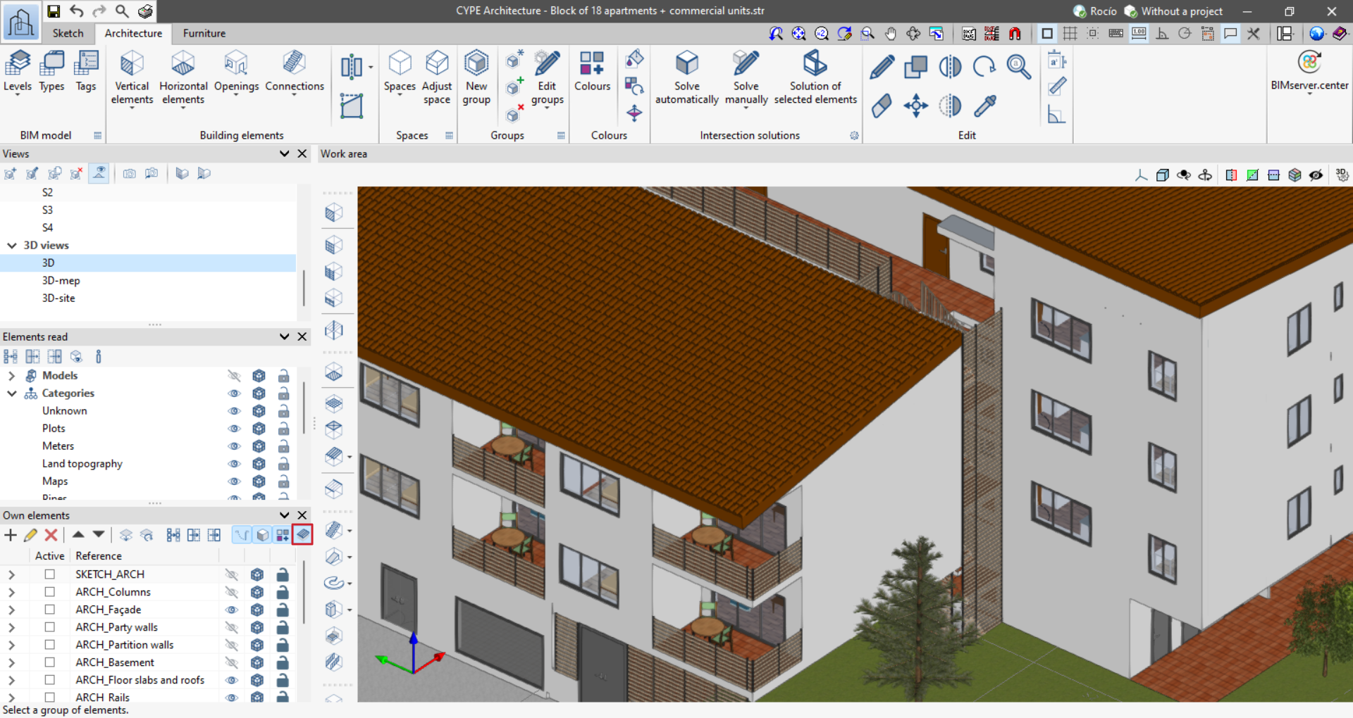
Modelling the building elements
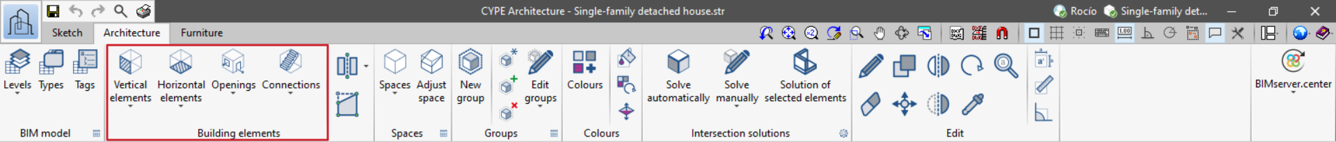
The "Architecture" tab includes all the tools for entering and editing the building elements that make up the architectural BIM model.
Once the sketch drawing has been created using grids, lines or surface areas, the building elements are entered, taking the sketch elements as a reference. Please note that sketch elements do not need to be included in order to create the building elements.
Vertical elements
The program provides the option of inserting vertical elements such as walls, curtain walls, louvres, railings and columns.
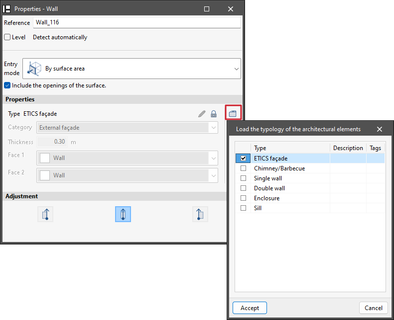
After activating one of these options, a floating menu is displayed which allows the characteristics of the element to be created to be defined.
In this menu, several features can be managed, such as typing the reference, activating or deactivating the automatic level detection, selecting the specific entry mode for each element, setting the height, or adjusting or setting the insertion point, depending on the element selected.
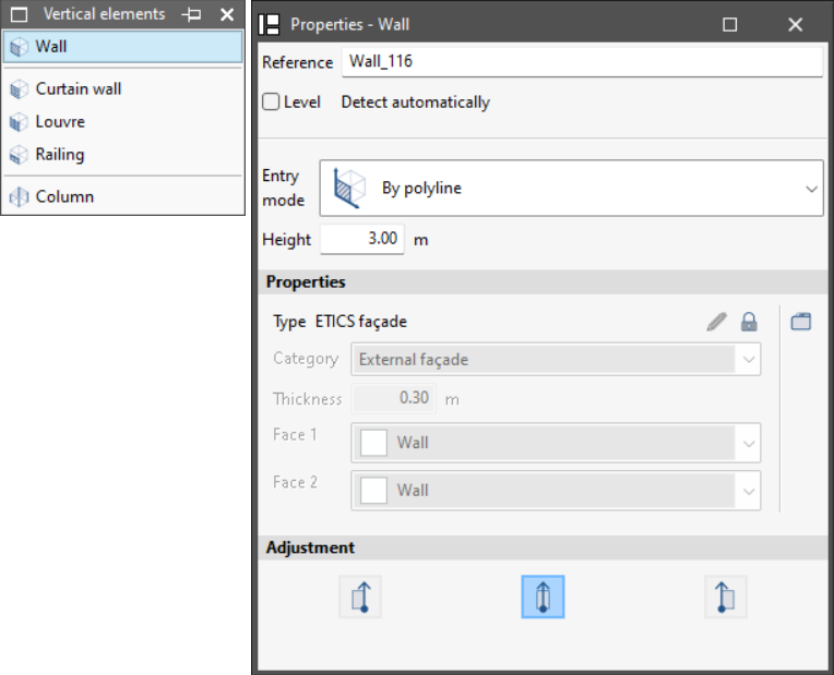
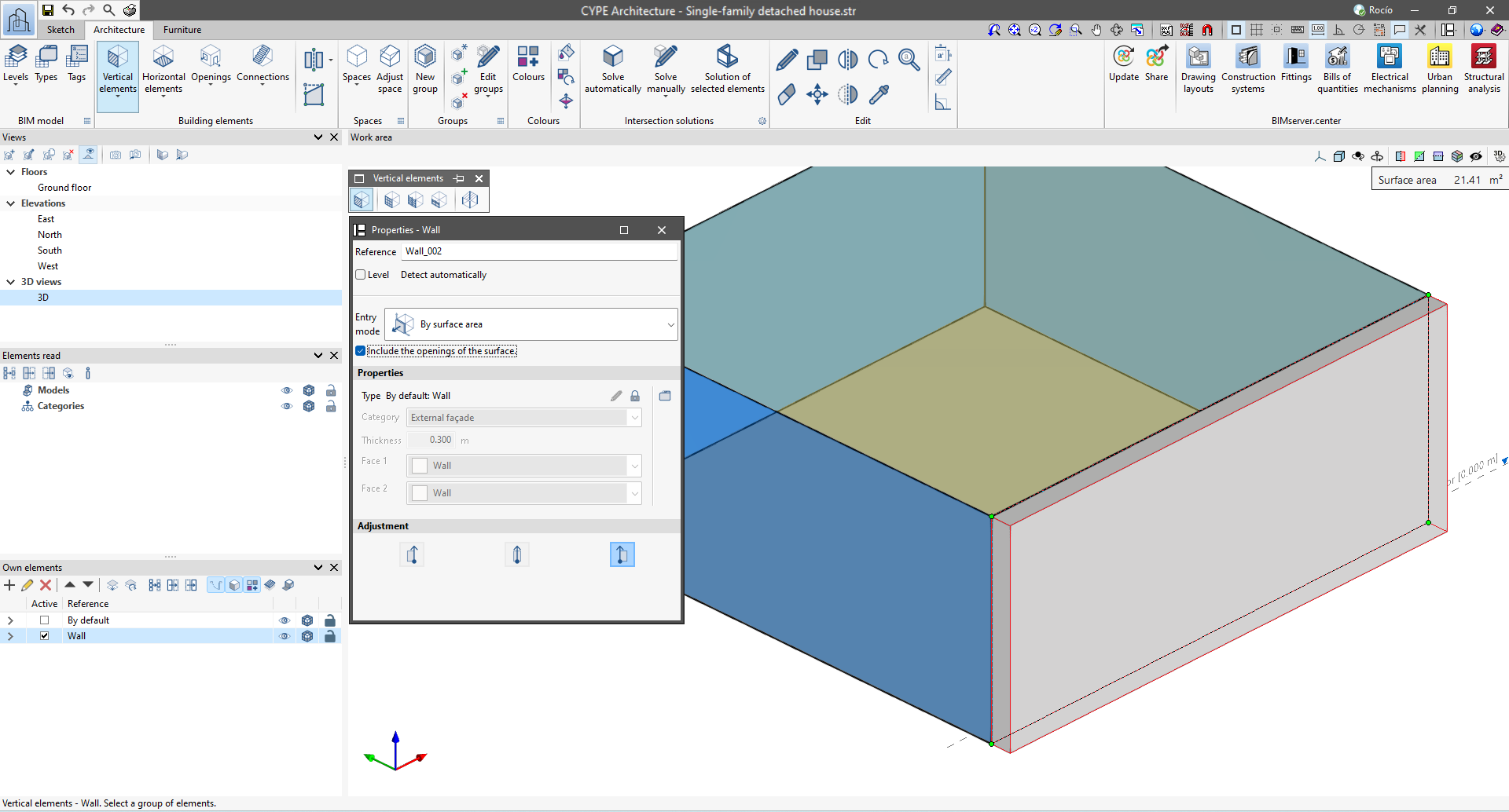
Each of the elements can be entered in different ways:
- Wall: can be entered by polyline, by points or by surface area.
- Curtain wall: can be entered by segment and height, by points or by surface area.
- Louvre: can be entered by segment and height, by points or by surface area.
- Railing: can be entered by points or by sketch line.
- Column: can be entered by points or by sketch line.
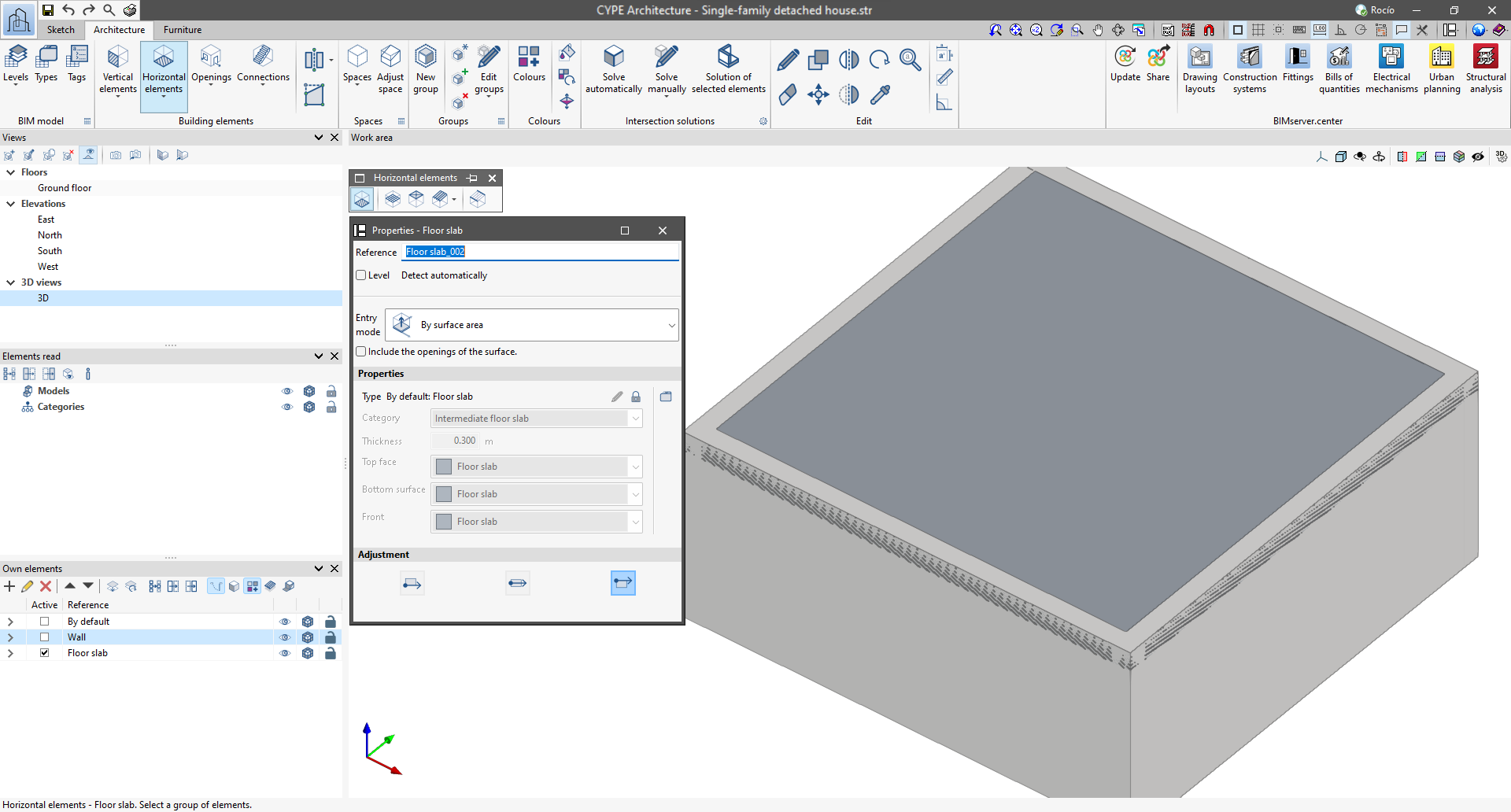
Horizontal elements
The program provides the option of entering horizontal elements such as floor slabs, suspended ceilings, slope formation, roof tiles and beams.
After activating one of these options, a floating menu is displayed which allows users to define the characteristics of the element to be created.
In this menu, several features can be managed, such as writing the reference, activating or deactivating the automatic level detection, selecting the entry mode that is specific to each element and adjusting it to suit the element in question.
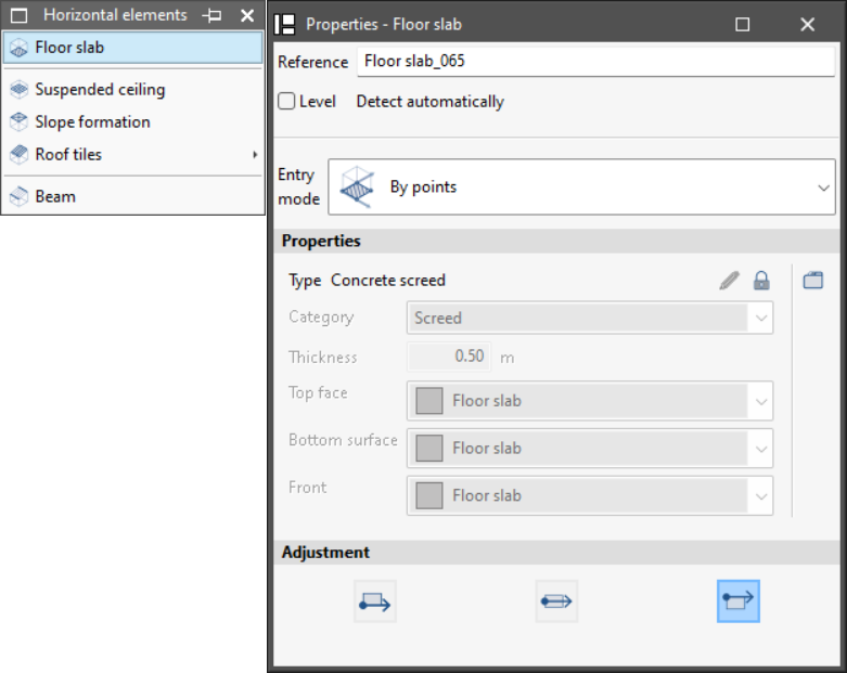
Each of the elements has different ways of being entered:
- Floor slab: can be entered by points or by surface area.
- Suspended ceiling: can be entered by points, by surface area or by outlines on plan.
- Slope formation: can only be entered by reference points. The elevation difference and the height of the drain can also be set.
- Beam: can be entered using two points and using sketch lines.
- Roof tiles: this section offers two options, "Roof tiles" and "Special roof element". Roof tiles can be entered by points or by surface area.
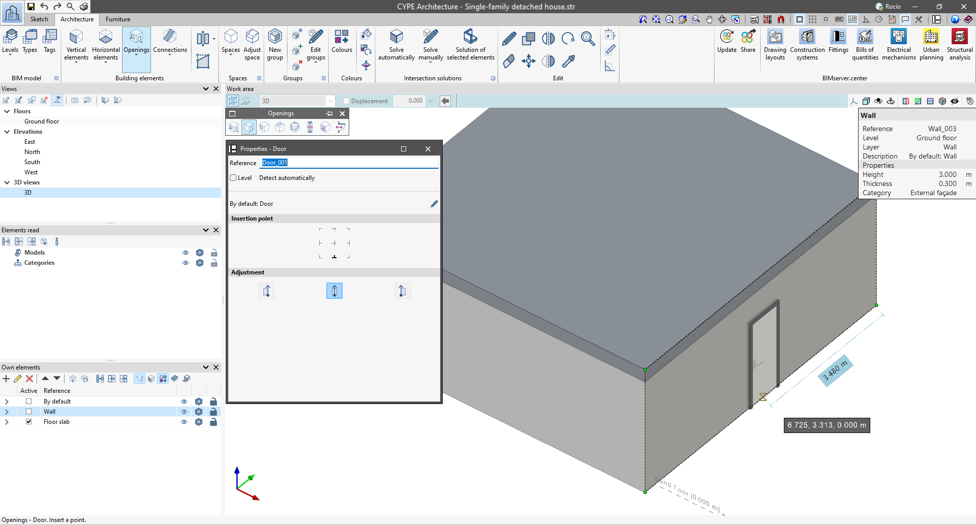
Openings
The program allows users to enter openings with the following options: "Opening", "Door", "Window", "Skylight", "Glazed surface", "Position", "Update openings" and "Change opening direction".
After activating one of these options, a floating menu is displayed which allows users to define the characteristics of the element to be created.
In this menu, various features can be managed, such as entering the reference, activating or deactivating the automatic level detection, selecting the specific entry mode for each element, and adjusting and setting the insertion point, depending on the element in question.
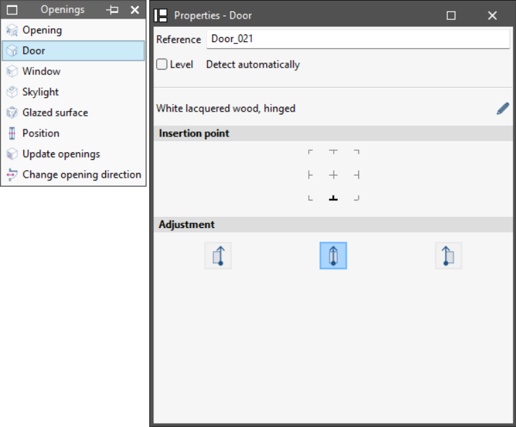
Each of the building elements has a different entry mode:
- Opening: can be entered by geometry or by points.
- Door: can only be entered by reference points.
- Window: can only be entered by reference points.
- Skylight: can only be entered by reference points.
- Glazed surface: can be entered by points or by surface area.
- Position, Update openings or Change opening direction: unlike the other options, a pop-up menu does not appear when selecting these options. In this case, the element to be modified must be selected.
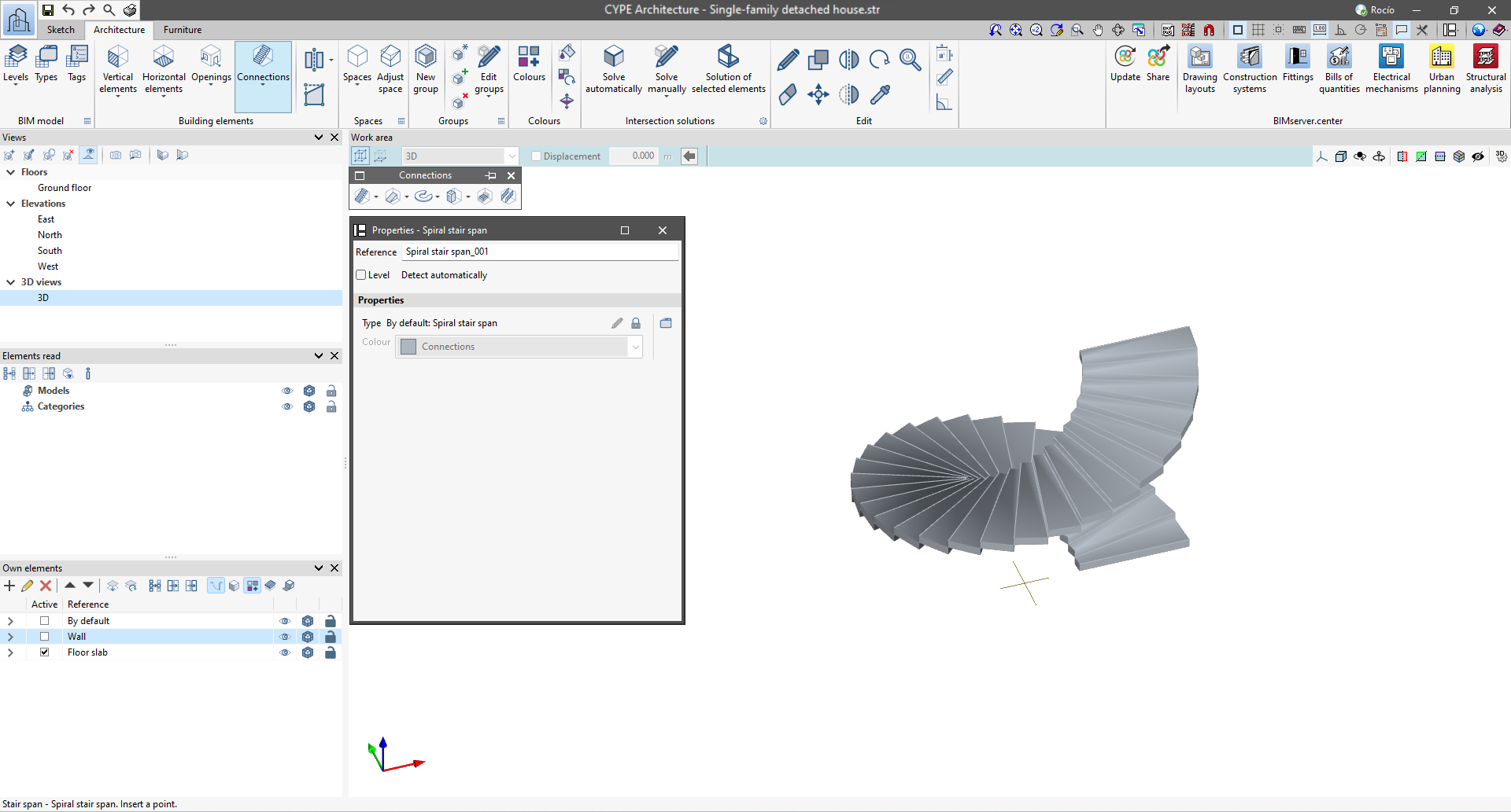
Connections
The program allows users to enter connections via the following options: "Staircase span", "Ramp span", "Curved ramp span", "Elevator/Lift", "Landing" and "Railing".
After activating one of these options, a floating menu is displayed which allows users to define the characteristics of the element to be created.
In this menu, several features can be managed, such as entering the reference, activating or deactivating the automatic level detection and adjusting to suit the element in question.
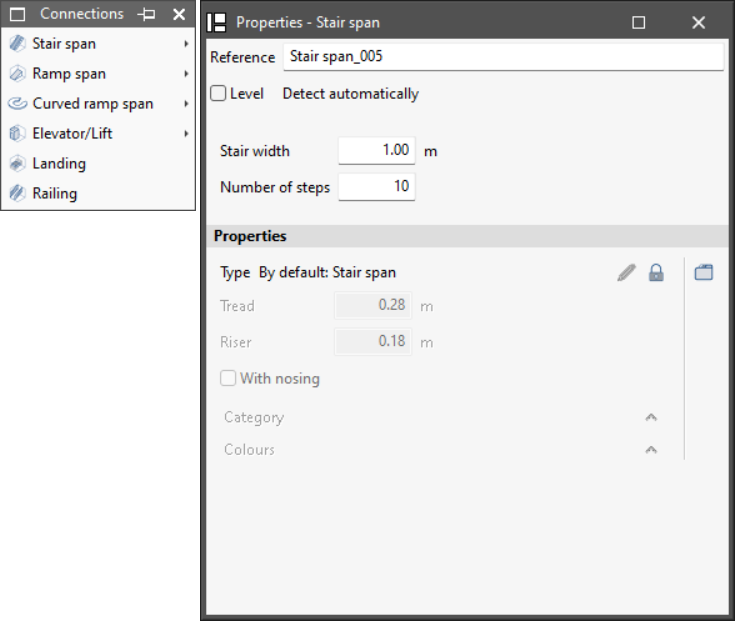
Each of the elements has different options:
- Staircase span: allows users to create staircase spans, staircases defined by three points, stair cores and spiral staircase spans.
- Ramp span: allows users to create ramp spans, ramp spans defined by three points and ramp cores.
- Curved ramp span: allows users to create curved ramp sections given the height and width, curved ramp sections given the centre and two points, as well as to extend the radius and move the centre.
- Lift/Elevator: allows users to enter lifts by reference points and defined by three points.
- Landing: allows users to enter stair or ramp landings by geometry, by points or by surface area.
- Railing: allows users to enter the railings by reference points.
Therefore, users are recommended to create all the necessary types for the BIM model before entering the building elements. This way, users can make the most of the functionality of the types and ensure coherence in the construction project.