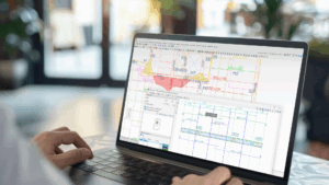
When designing a BIM model, we know how important it is to make the entry and editing of elements as simple as possible. That's why we have made it easier with CYPE Architecture. Let us introduce you to the different ways to divide walls and floor slabs, as well as to edit and adjust the geometry of your model.
The "Architecture" tab contains the "Edit geometry", "Divide wall or floor slab", "Adjust vertical and horizontal elements" and "Define insertion point" tools, which provide great flexibility and versatility in the BIM model design process. Let's see how they all work:
Editing the geometry
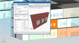
The "Edit geometry" tool can be used in different ways depending on the building element to be edited (walls, curtain walls, lattices and railings) and the type of view used (3D or plan view).
Editing vertical elements
Editing in a 3D view
When selecting the "Edit geometry" tool, we can place ourselves on one of the vertices of a wall to move this point and change the shape of the element.
If, however, we place ourselves on any edge of the element, we will be able to move it to its new position.
Editing in a plan view
If we are working on a plan view, the tool prioritises the movement of edges over the ends, which allows us to stretch or contract the length of the elements easily.
Editing horizontal elements
For horizontal elements, if we place the cursor on the vertex, we can move its position. On the other hand, if we place the cursor on the edge, we can move it. This tool allows us to edit the geometry both in 3D and plan views.
Adjusting vertical and horizontal elements
From "Adjust vertical elements" and "Adjust horizontal elements" in the "Building elements" section, it is possible to change the adjustment (right, left or centred) of one or more vertical or horizontal elements about their entry line.
To change the setting of one or more elements, we select the new setting to be used, and then select the elements to be adjusted.
These tools work with the elements that can be adjusted when they are entered: walls, curtain walls, lattices, rails and floor slabs.
Defining an insertion point
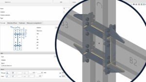
From "Define insertion point" a new insertion point can be assigned to the already entered element in the simplest possible way.
To change the insertion point of one or more elements, we select the new insertion point we want to use and then select the elements we want to redefine with respect to the insertion point.
This tool works with elements that support an insertion point when entered, such as columns and beams.
Dividing walls and floor slabs
When selecting the "Divide wall or floor slab" tool, it is split into two options: "Divide wall or floor slab" and "Divide wall at a point".
Dividing a wall or floor slab
The first one allows us to divide walls or floor slabs from two points that cut them. For walls, we must use 3D views, while for floors the function is similar regardless of whether we use a 3D view or a plan view.
Dividing a wall at a point
With the second option, "Divide wall at a point", a wall can be divided by a single point, both in plan views and in other types of views. This makes it considerably easier to use the program, especially when designing in a plan view.


