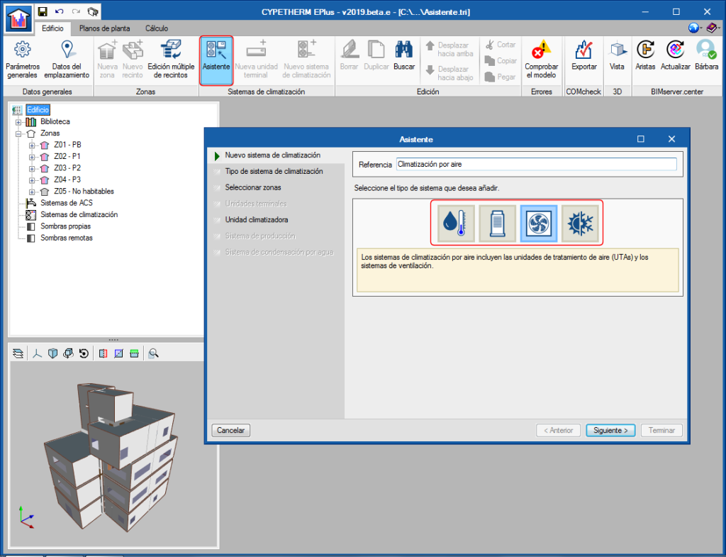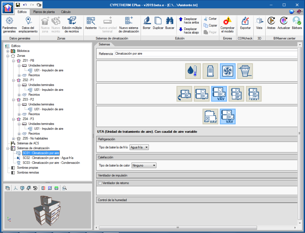
A new tool has been implemented to define the air conditioning systems of the building in a step-by-step way. Using the "Assistant" button, users can create a new complete air conditioning system, or add new terminal units to systems that are already defined in the project. This tool improves the ergonomics of the program, by allowing terminal units to be added and deleted in a single step in the different thermal zones of the building.
When the “Assistant” button of the "Climate control systems" section of the top menu of the program is selected, the window in which the name of the new system is to be provided appears. Users must also choose its typology amongst the water, direct expansion, air or constant performance system categories.
To the left of this window, users can see the steps which the assistant will guide him through to complete the definition of the air conditioning system. The different sections are displayed in black if they must be defined in accordance with the selected options. The buttons on the lower bar allow users to navigate in the assistant.
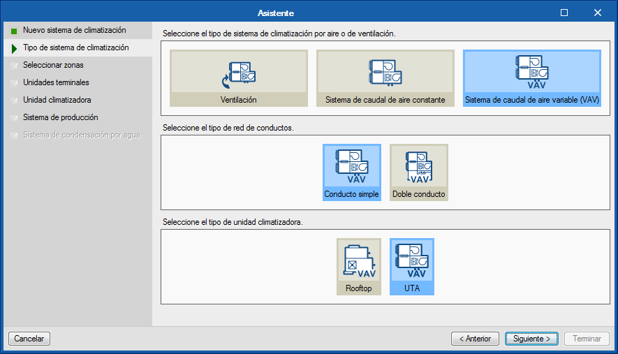
In the second step of the assistant, users must choose the type of air conditioning system, in accordance with the category chosen previously.
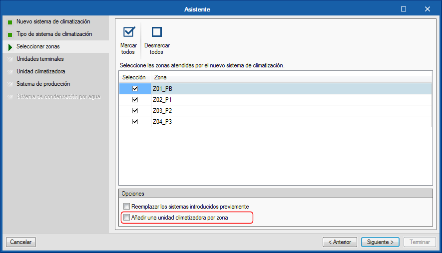
In the third step, users must select the areas of the building that will be associated with the air conditioning system. The assistant will automatically create the terminal units of the system defined in each of the selected zones. By default, all these terminal units will be connected to a single production system or to a single air conditioning unit in the case of air conditioning systems. On the other hand, if the option "Add an air conditioning unit per zone" is chosen, the terminal units created in each zone will be connected to their respective system.
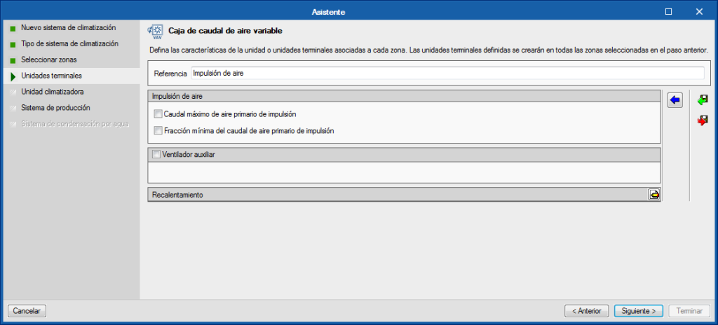
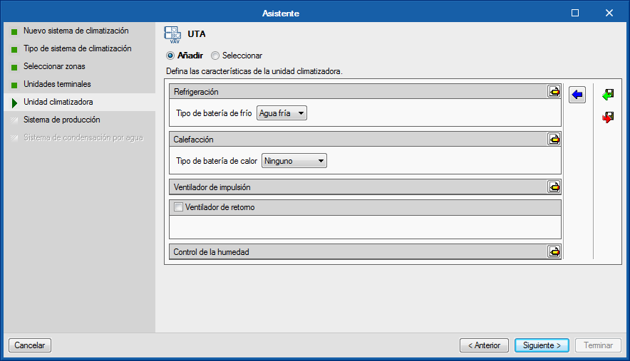
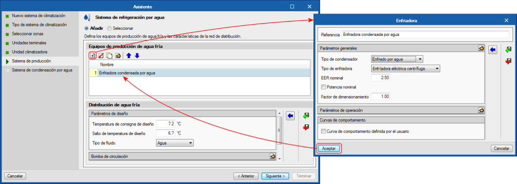
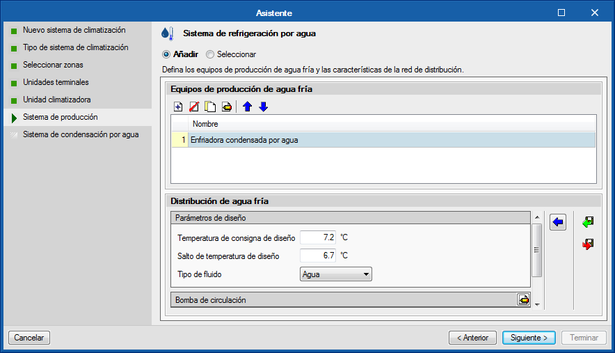
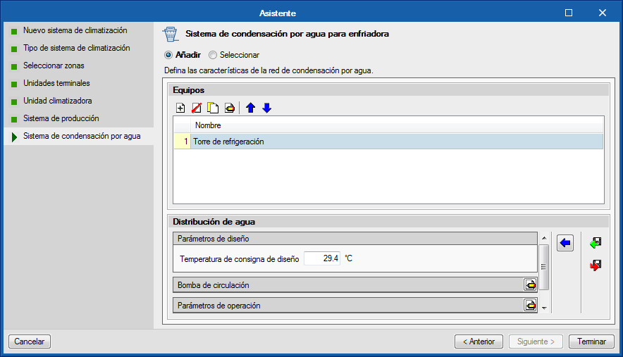
The following steps of the assistant run through the different elements that make up the type of air conditioning system that has been chosen, so users can define its properties. In general, the panels corresponding to the terminal units and air conditioning systems that are available in the program will be shown, as they are required.
In the images, a variable air flow system has been defined that contains an air conditioning unit with a cold water battery connected to a water-cooled chiller. The assistant successively displays the panels to define the variable flow type box terminal units, the variable flow ATU, the water cooling system the chiller contains and finally, the water condensing system for the chiller. At the end of the wizard, the new elements of the air conditioning system will appear in the diagram of the main screen.


