CYPELEC Core, CYPELEC NF and CYPELEC REBT design low voltage installations. In previous versions of CYPELEC Networks, users had to manually introduce the loads that correspond to the low voltage installations (calculated in the aforementioned programs), which are supplied by the medium or high voltage network, and were going to be analysed in CYPELEC Networks.
As of the 2019.b version, and thanks to the Open BIM connection of these programs, CYPELEC Core, CYPELEC NF and CYPELEC REBT can export the demanded or foreseen power (power and power factor) that is required by the installations they design to the BIM model.
This way, when a project is begun in CYPELEC Networks, by connecting to the BIM model to which the demands of the installations that have been designed in CYPELEC Core, CYPELEC NF and CYPELEC REBT have been exported, CYPELEC Networks users will be able to import the IFCs that are generated by the programs and will decide which loads will be part of the high or medium voltage diagram.
To select these loads, CYPELEC Networks has a new tool represented by ![]() , located in the “Terminal elements” section of the toolbar.
, located in the “Terminal elements” section of the toolbar.

When this tool is selected, the program allows users to select the desired load among those imported from the BIM model to include it in the diagram and continue with the electrical installation. Each time this tool is selected, one of the imported loads can be selected.
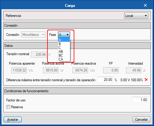
If the imported load is single-phase, it will be possible to select to which phase is connected.
In the project, imported loads can be combinedand user can introduce their own loads created directly in CYPELEC Networks.


