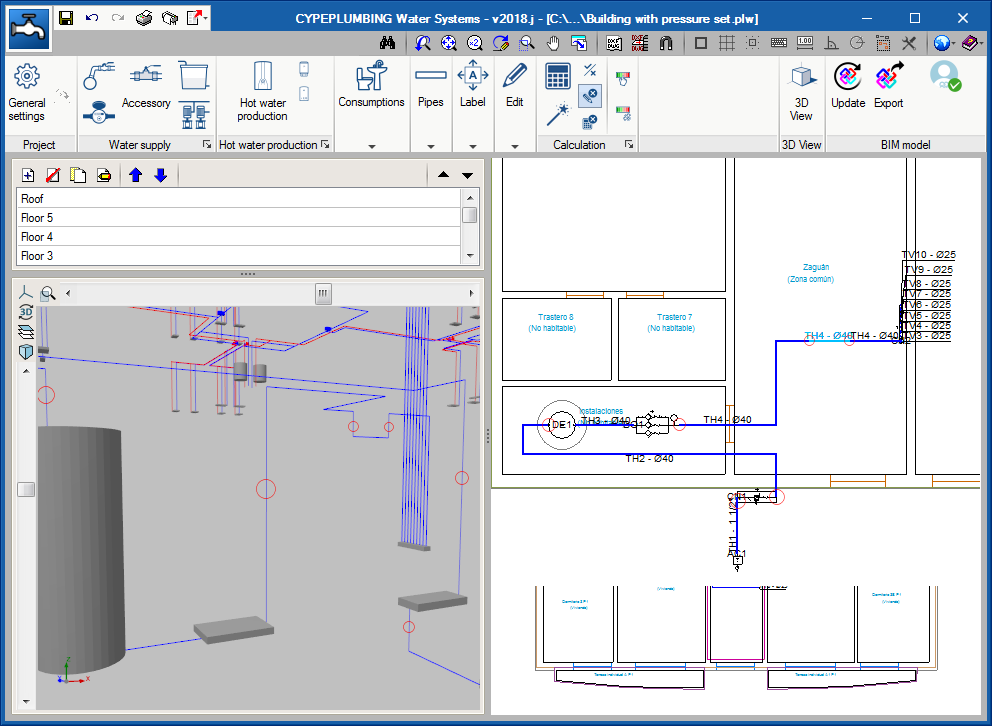
The program generates, in the 3D view, any vertical spans that join two elements introduced in the same floor but with different elevations. This already occurred as of the 2018.g version for consumption elements. These elements are introduced in the same floor plan as the pipe that feeds them. In the 3D view they appear joined by a vertical span without the need to have to manually introduce it.
Now, these vertical spans are also generated between pipes with different elevations or between other elements to which users assign a different elevation to that of the plane along which the pipe runs (connections, meters, tanks, pressure groups ...).
The vertical spans that are generated automatically by the program are drawn in the 3D view in a slightly lighter colour than the pipes and verticals spans introduced by users. The vertical spans that are generated will have the same diameter as the pipe from which they descend. If users wish to modify their diameter, the vertical span must be introduced manually using a vertical pipe.
In the attached image, the vertical spans that have been generated automatically are marked with a red circle (both in the 3D view and in the plan view).


