As occurs in CYPE 3D, as of the 2018.a version, CYPE-Connect includes the analysis, design and check of prequalified connections in accordance with ANSI/AISC 358-10 (Prequalified Connections for Special and Intermediate Steel Moment Frames for Seismic Applications) and ANSI/AISC 341-10 (Seismic Provisions for Structural Steel Buildings).
Prequalified connections are applied to Special Moment Frames (SMF) and Intermediate Moment Frames (IMF) as indicated in the ANSI/AISC 341-10 code.
It is possible to define prequalified connections in projects in which the rolled and welded steel code: ANSI/AISC 360-10, has been selected.
For more information on which prequalified connections have been implemented, how beams interact at the same node, the checks that are carried out and drawing that are generated, please consult the relevant sections in the new features of CYPE 3D of this webpage.
Operation in CYPE-Connect
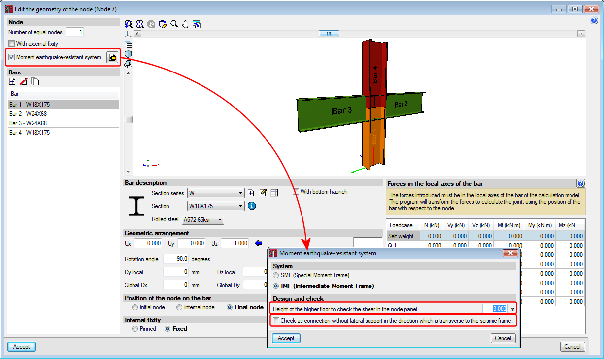
To calculate prequalified connections in CYPE-Connect, users must select the rolled steel code: ANSI/AISC 360-10, the connection in question must have the geometry corresponding to one of the implemented prequalified connection types, and the moment earthquake-resistant system option in the “Edit the geometry of the node” dialogue box must be activated with one of the available systems (SMF – Special Moment Frame, or IMF – Intermediate Moment Frame).
Even though no checks are carried out on cold-formed steel for prequalified connections, for internal operation purposes of the program, the selected cold-formed steel must be one CYPE-Connect considers to be compatible with the ANSI/AISC 360-10 code, such as “AISI S100-2007”.
As well as the earthquake-resistant code that is used, the following parameters must be defined:
- The height of the higher floor
It is defined in the dialogue box where the earthquake-resistant system is selected and is required to estimate the shear of the column and check the shear in the node panel. - Check as connection without lateral support in the direction which is transverse to the seismic frame
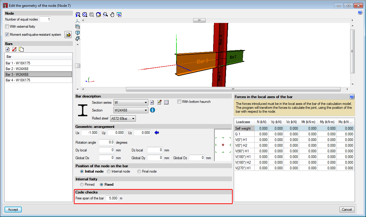
To check the requirements of article “E3.4c” of the “ANSI/AISC 341-10” code, this option must be marked, which is also available in the dialogue where the earthquake-resistant system is selected. - Free span of the bar
It is used to establish the moment at the face of the column. It is introduced in the “Edit node geometry” dialogue box (“Check” section).