The export to IFC format (Industry Foundation Classes) carried out by CYPECAD MEP, now includes the thickness of the air conditioning and ventilation ducts that have been designed by the program.

Air conditioning. Thermal loads represented on-screen using contour lines
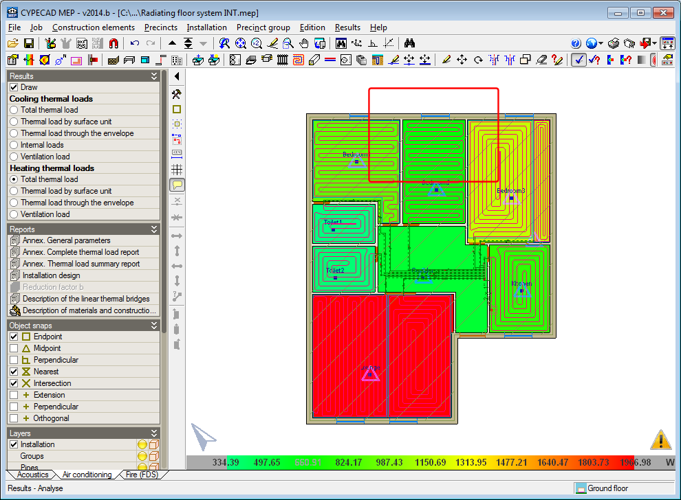
The 2014.b version includes a practical and important new feature which allows users to know the thermal loads of the precincts of a floor of the building at a single glance. It consists of a display, using contour lines, of the heating and cooling thermal loads that have been calculated for each precinct.
Once the analysis has been carried out in the Air conditioning tab, users can activate the Draw option, within the new Results section in the lateral menu. By activating this option, the data that can be represented on-screen related to the heating and cooling thermal loads is displayed:
- Cooling thermal loads
- Total thermal load
- Thermal load by surface unit
- Thermal load through the envelope
- Internal loads
- Ventilation load
- Heating thermal loads
- Total thermal load
- Thermal load by surface unit
- Thermal load through the envelope
- Ventilation load


The thermal cooling or heating loads can be selected if they have been activated for the analysis in the Load calculation section of the General data dialogue box (Job > General data). The “Air conditioning” option in this dialogue box activates the analysis of both thermal loads and the “Cooling” and “Heating” options only activate the loads their name indicates.
The external, inhabitable, or habitable precincts for which the option “Not air conditioned” has been activated, will appear in white when either the cooling or heating thermal loads are selected. Habitable precincts, whose design parameter for the thermal analysis has the option “Only heated” activated, will appear in white when any type of cooling thermal load has been activated.
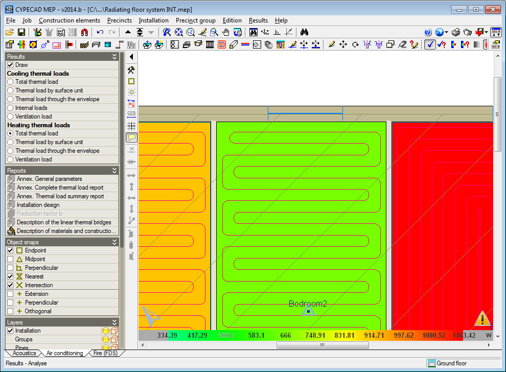
As with any data representation carried out by CYPE programs using contour lines, a scale of values of the colours that are displayed is present in the bottom part of the screen. The colour range used in the representation can be changed using either of the two colour palettes in the Colours for the representation of contour maps dialogue box (“General configuration button ![]() ” located in the top right-hand corner of the screen > “Colours for the representation of contour maps” option). The palette with least colours allows for the texts to be visualised better on-screen, although the precincts may be represented with colours which are similar to each other. The palette with most colours may hinder the reading of some texts on-screen but the precincts are represented with a more varied colour range.
” located in the top right-hand corner of the screen > “Colours for the representation of contour maps” option). The palette with least colours allows for the texts to be visualised better on-screen, although the precincts may be represented with colours which are similar to each other. The palette with most colours may hinder the reading of some texts on-screen but the precincts are represented with a more varied colour range.


The maximum numerical value that is visible on-screen always corresponds to the colour at the right-hand end of the selected palette and the minimum value with that at the other end. This allows the precincts which are represented on-screen with similar colours to change and so can be better distinguished between one another upon zooming in.
Vertical openings in beams
Implemented in the previous version (2014.a) was the introduction and check of horizontal openings in beams, for dropped rectangular, “L” or “T” sections (without lattice reinforcement) using the Advanced beam editor of CYPECAD and Continuous beams.
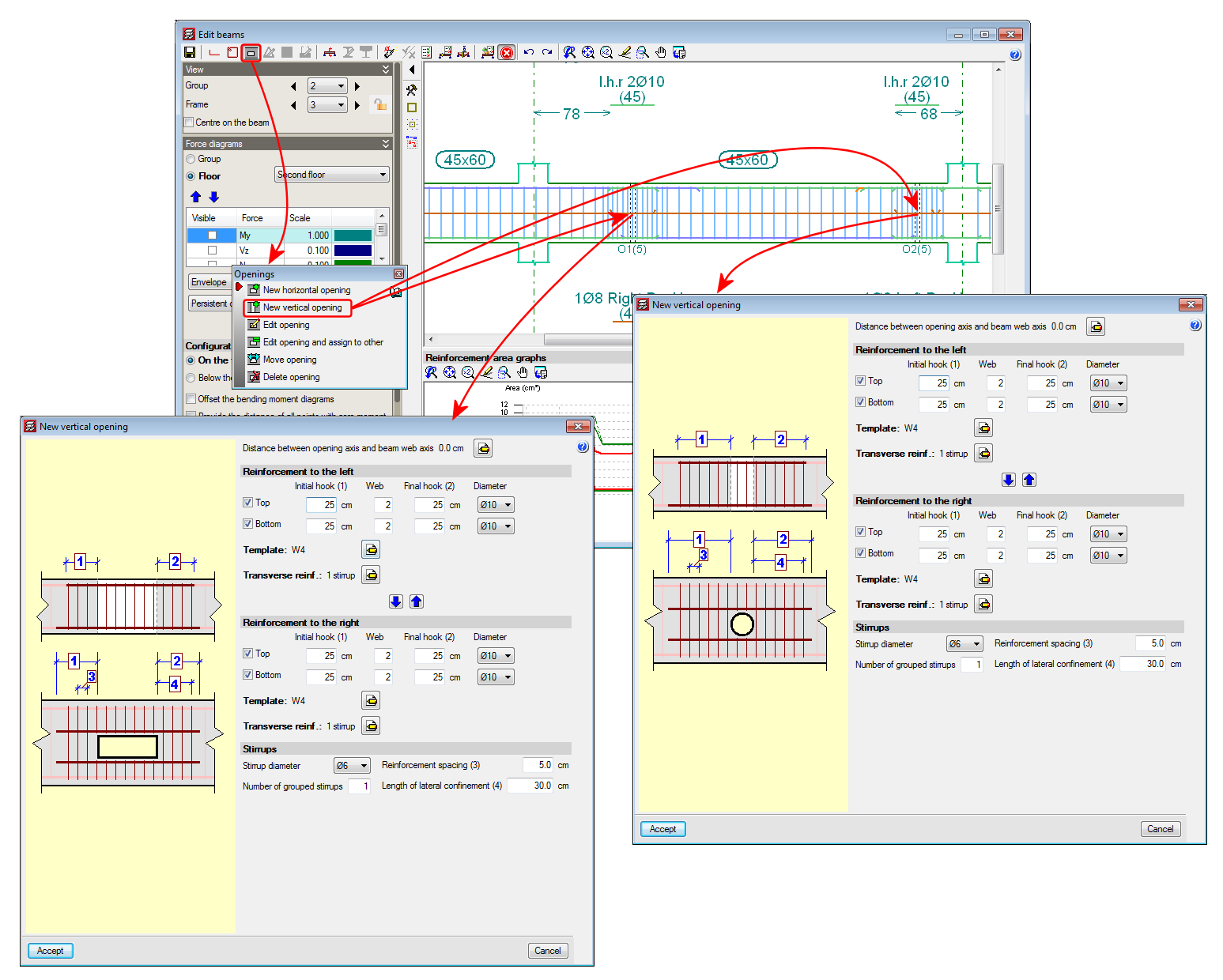
Now, with the 2014.b version, vertical openings (rectangular or circular) can be introduced in flat or dropped rectangular, “L” or “T” beams (without lattice reinforcement).
A new option, New vertical opening, has been implemented to introduce the vertical openings, within the Openings dialogue box (Edit a beam from the Results tab of CYPECAD using the advanced beam editor > select the ![]() button of the editor).
button of the editor).
The program allows for vertical openings to be introduced in the flanges and webs of flat and dropped beams, as long as the following conditions are met:
- The transverse dimension of the vertical opening must be less than one third of the width of the web or less than two thirds of the width of the flange, depending on the zone in which the opening is situated.
- The length of the opening must be less than the width of the web and the depth of the beam.
- The position of the vertical opening must guarantee that the cover is respected at all the surfaces of the opening.
- The free distance between a vertical opening and the support of the beam must be greater than the lateral confinement length of the opening.
Furthermore, the free distance between consecutive openings, be they horizontal or vertical, must be greater than two times the depth of the beam and greater than the width of the web of the beam.
Neither horizontal nor vertical openings may be introduced in the confinement zones established in the selected seismic code.
The resulting section of the beam, having applied the reduction due to the presence of the opening, will be checked using the criteria of the selected code as will, besides the reinforcement of the beam, the reinforcement provided in the opening.
The conditions of the position and dimensions of the openings of the horizontal openings can be consulted in the new features of the 2014.a version.
When a vertical opening is introduced and cuts the reinforcement of the frame, the program emits a warning informing users that the arrangement of the reinforcement bars proposed by the program is to be revised, once the opening has been introduced and checked, as there may be a simpler reinforcement arrangement that can be executed on site. Users could even position some of the additional reinforcement bars of the frame in a second layer so the reinforcement arrangement of the opening would be easier to execute.
The remaining edition and check options of the Ultimate Limit States (U.L.S.) of the openings, operate in the same manner as for horizontal openings and can be consulted in the Advanced beam editor. Horizontal openings in beams section in the new features of the 2014.a version.
Please bear in mind that neither the horizontal nor vertical openings are considered during the analysis phase, hence their position and dimensions are restricted (as has been indicated previously in their introduction conditions) so the forces that are obtained can be considered valid.
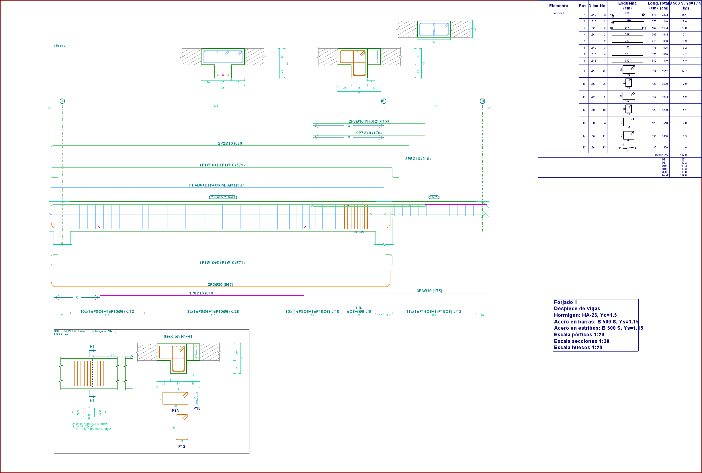
The reinforcement details of the vertical openings are generated automatically within the details of the frame, in the same way as for horizontal openings.
Calculation of the properties of the masonry construction elements
The homogenised values of the properties of the construction elements that are introduced in CYPECAD, to consider their effect in the dynamic analysis of buildings exposed to seismic action, are, as of the 2014.a version: the Thickness of the masonry, Modulus of elasticity X, Modulus of elasticity Y, Shear modulus XY, Poisson’s ratio XY and the Surface load.
All this data is introduced in the Masonry properties – homogenized values – (Beam Definition tab > Loads > Construction elements > Add or Edit option > edit selected type button ![]() or edit type list button
or edit type list button ![]() and add
and add ![]() ). It is the manufacturers, who due the tests they have carried out on their products, will be able to provide more exact values.
). It is the manufacturers, who due the tests they have carried out on their products, will be able to provide more exact values.
For those cases in which the manufacturers have not provided the required data, a tool has been implemented in the 2014.b version that calculates the homogenised values of the masonry properties based on geometric and resistance data that users can know more easily. This tool is accessed from the previously mentioned dialogue box: Masonry properties – homogenized values, selected using the Property analysis button (![]() ).
).

The properties required by the tool are:
- Type of construction element
- Internal partition
- External wall, visible
- External wall, to be covered
- Number of leaves (single or double)
- Material
- Type of mortar
- Type of joint
- Mortar resistance
- Standard compressive strength of the unit

In order to define the material, type of mortar, type of joint, mortar resistance and the standard compressive strength of the unit, users must select the adequate option amongst those offered by the program in a drop-down list.