New features of the 2016.g version
New interactions between shell elements, bars and nodes
As of the 2015.1.c version, users could define shell elements in CYPE 3D. Shells connect to one another and to the rest of the structure in an explicit manner via their edges, allowing for only the following interactions to occur:
- Shell – Shell at edge
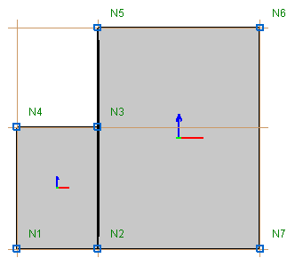
Two shells are connected to each other if they share one or more edges. In the example below, the shells are connected to one another at the edge defined between nodes N2 and N3.
- Shell – Bar end
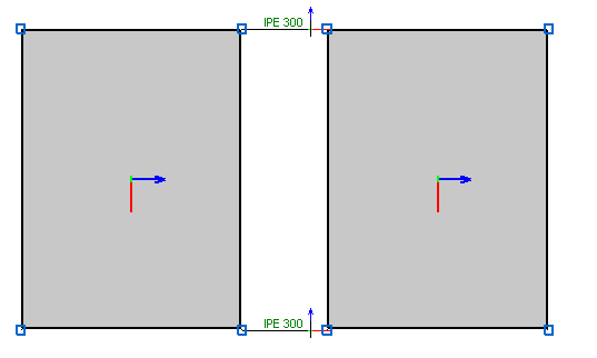
A bar can be connected to a shell via a shared node.
- Shell – Bar at edge
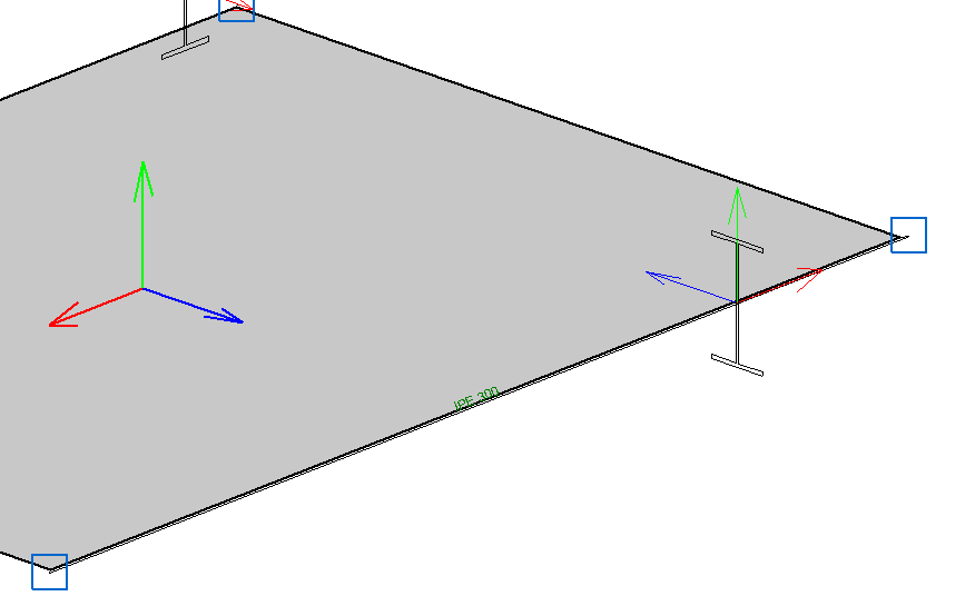
A bar is connected to a shell if it is completely contained in one of its edges.
As of the 2016.1.g version, the following additional interactions are permitted:
- Shell – Internal bar
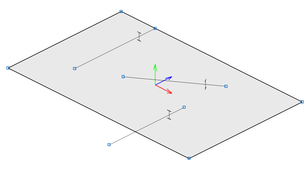
A bar is connected to a shell if it goes through it. The bar can be completely or partially contained within it.
- Shell – Internal bar end
A bar is connected to a shell if one of its end nodes is contained in the shell.
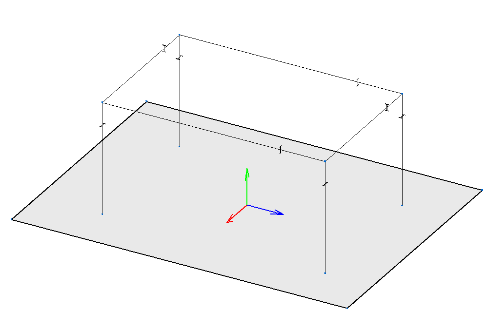
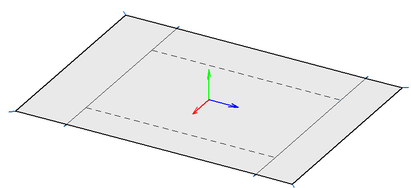
- Shell – Overlapping shell
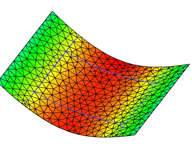
A shell is connected to another shell if they are both contained in the same plane and overlap one another. The properties and loads of the shell with the smallest area are applied.
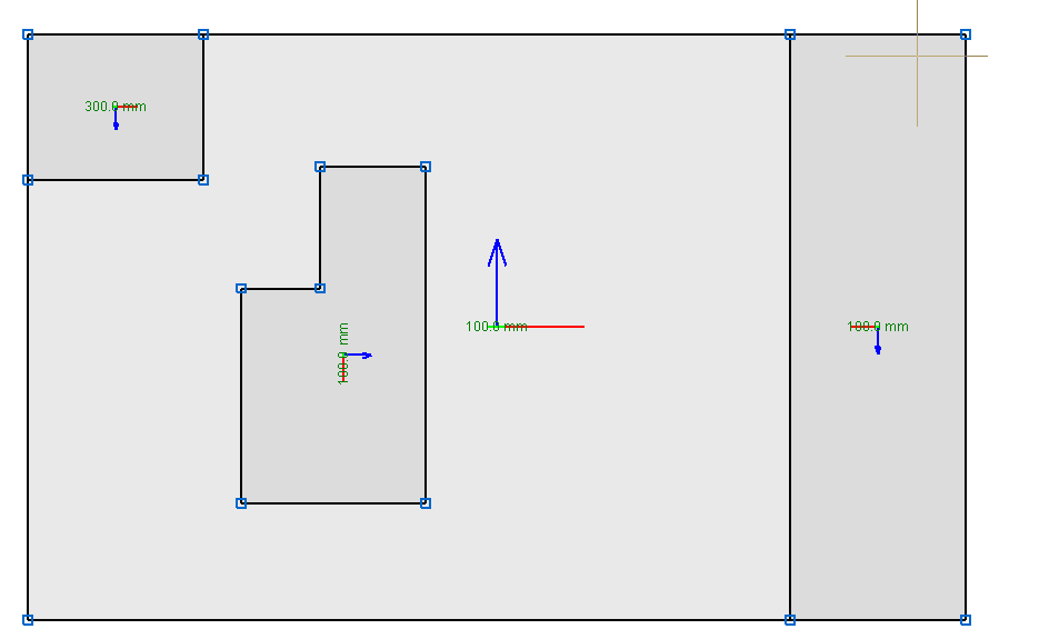
Under no circumstances can one shell be completely overlapped by others.
- Shell edge – Inside a shell
A shell is connected to another shell at the edge segments that are contained within the other shell.
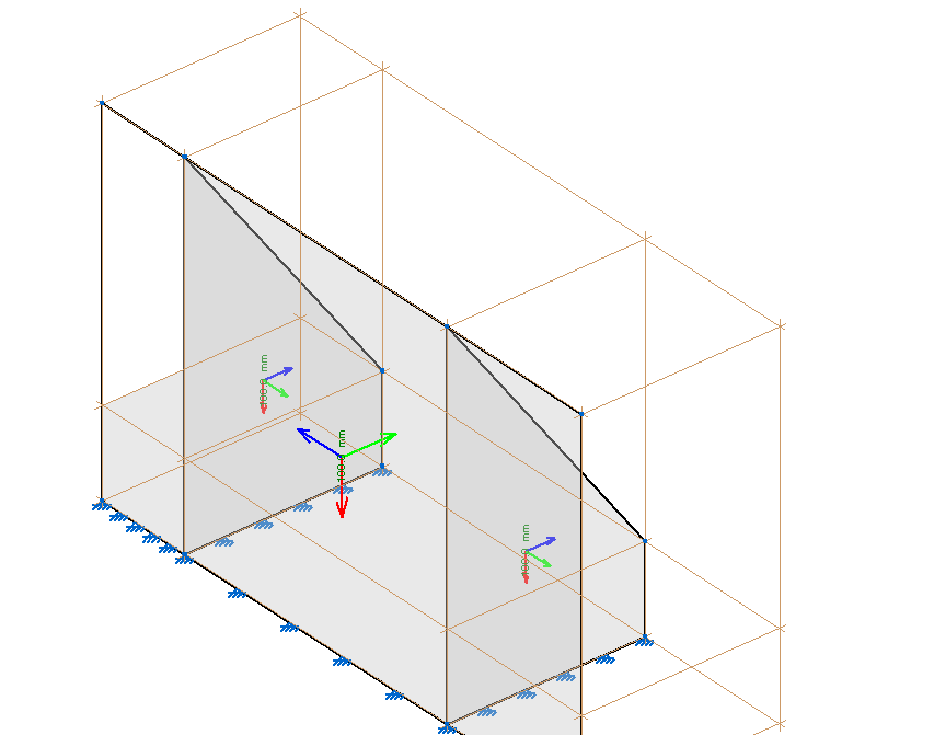
- Shell – Node inside the shell
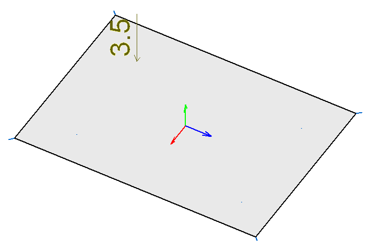
A node is connected to a shell if it is inside it. The editing possibilities of the internal fixity of the node are the same as for any other case. This interaction allows for point loads to be introduced on shells.
Connect/Disconnect bars from inside the shells
This option is located in the Bar menu. It allows users to indicate whether a bar, if it crosses a shell, is to be connected to it or not. It does not affect the Shell-Bar interaction at an edge. Bars that are not connected to shells are displayed with a discontinuous line.
Edit rotation angle of the local axes of a shell
This option is located in the Shells menu. It allows users to indicate a rotation angle with respect to the local x axis, by default. Using this option, the orientation of the axes of the shells can be adjusted.
Integration strips in overlapping shells
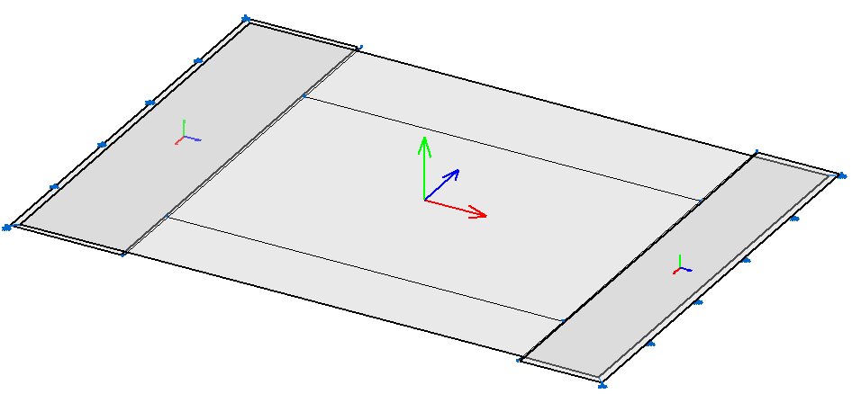
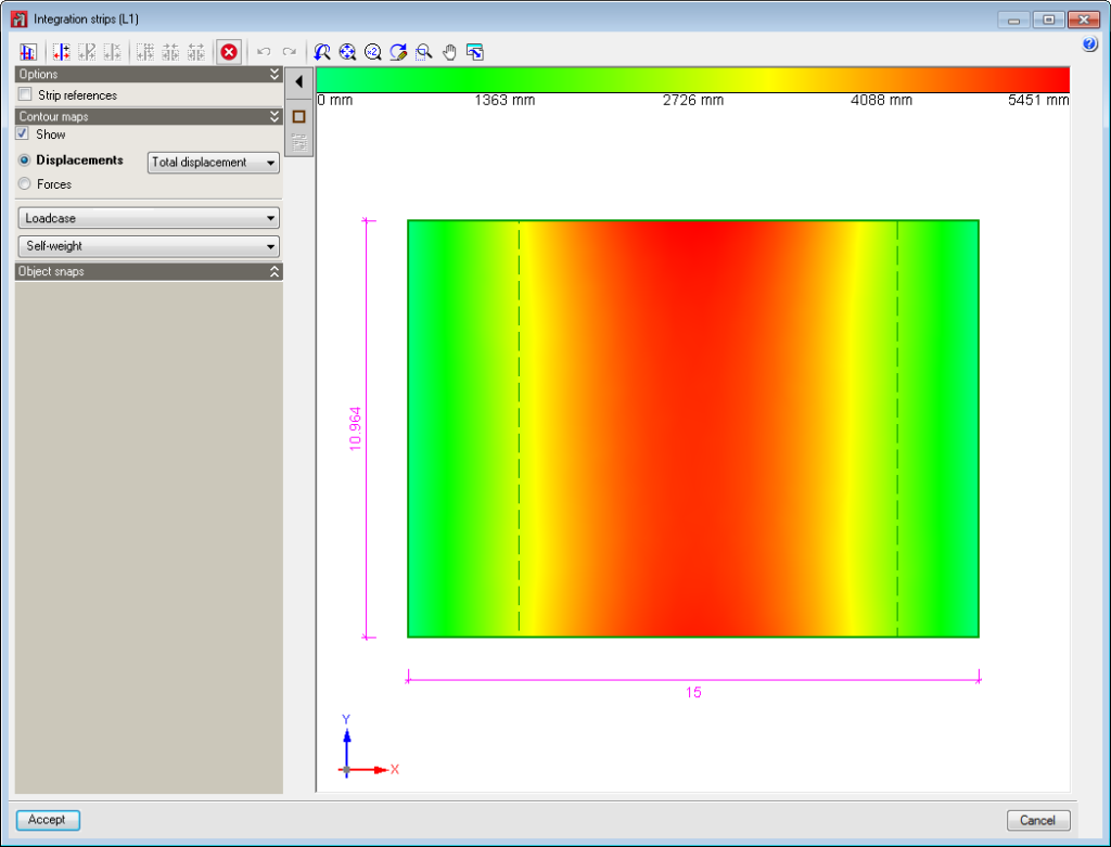
Integration strips can be drawn when shells contain other shells. Their axes do not necessarily have to coincide; the program transforms the forces from the reference system of the contained shells to those of the container shell.
The zone corresponding to the contained shells are marked with a discontinuous rectangle.
Internal fixity improvements of shells
When there are two shell edges with a shared node, if users indicate that the edges have free internal fixity, the shell will also be disconnected from the node.
CYPETHERM Suite. CYPETHERM HVAC LOADS
Export to COMcheck
A new option has been added with which users can export the thermal envelope and zones to COMcheck, a program offered by the US Department of Energy (DOE). Using the program, users can verify whether the requirements of the “International Energy Conservation CODE (IECC)”, of Standard 90.1 of ASHRAE are met, as well as those of various state codes.
A COMcheck file is automatically generated including the zones and properties of the thermal envelope of the building that has been introduced in the program. If several precinct group loadcases have been defined, only those which include the zones to be exported to COMcheck can be selected.

