New modules and programs
IFC Uploader (new program)
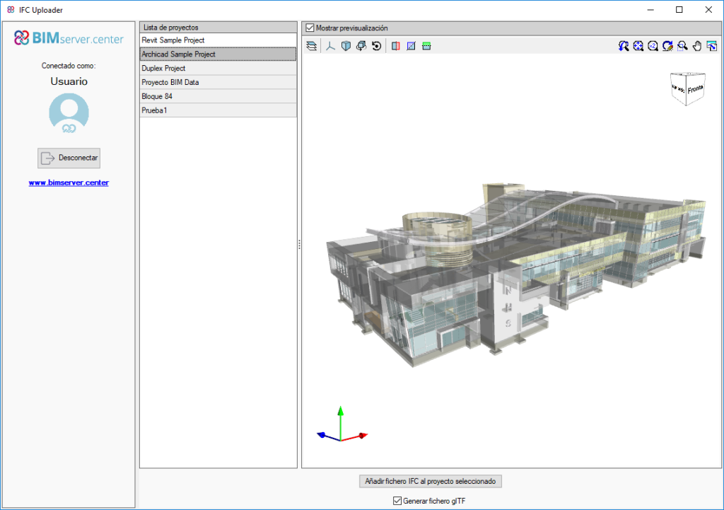
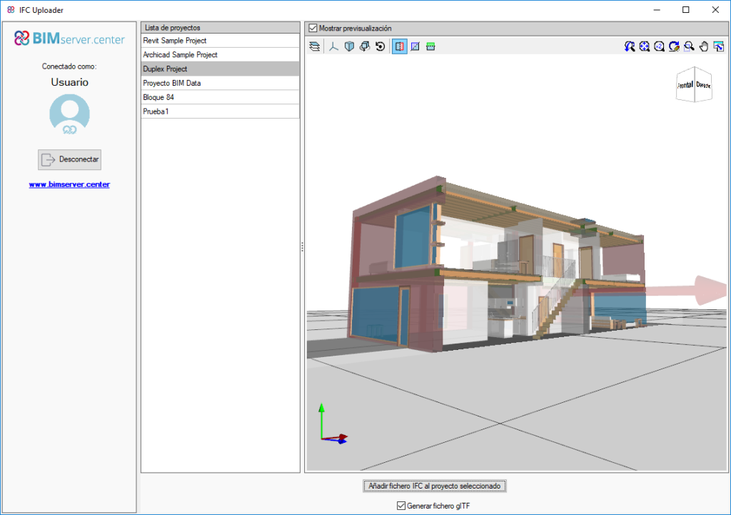
IFC Uploader is a free tool that allows users to add files in IFC format to projects on the BIMserver.center platform that also automatically generates GLTF files so they can be viewed, both on this platform and in the set of Open BIM workflow programs.
This application allows for other applications that generate standard IFC files, but do not currently have a direct communication with the BIMserver.center platform, to be integrated in the Open BIM workflow.
The tool has an integrated viewer to view the set of models linked to each project.
Open BIM Electrical Mechanisms (new program)
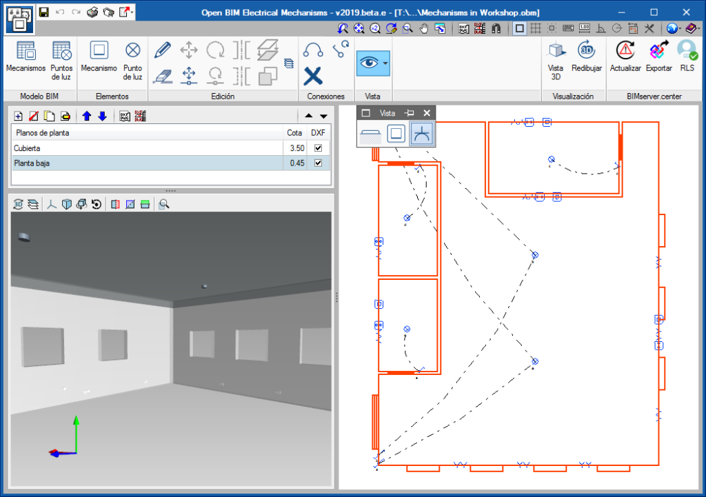
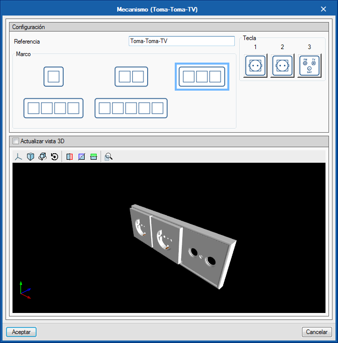
CYPELEC Electrical Mechanisms is a free program for users to design the arrangement of electrical mechanisms (such as switches, sockets and audiovisual and telephony connectors) based on an architectural model located on the BIMserver.center platform.
CYPELEC Electrical Mechanisms is integrated in the Open BIM workflow.
The program allows users to define the activation circuits by connecting mechanisms and light points.
The output of the program includes:
- IFC of the elements placed in the space and their 3D representation
- Floor plans
- Quantities in bc3 format
- Report with the materials schedule
- 3D view of the whole installation
Open BIM Sanitary Equipment (new program)
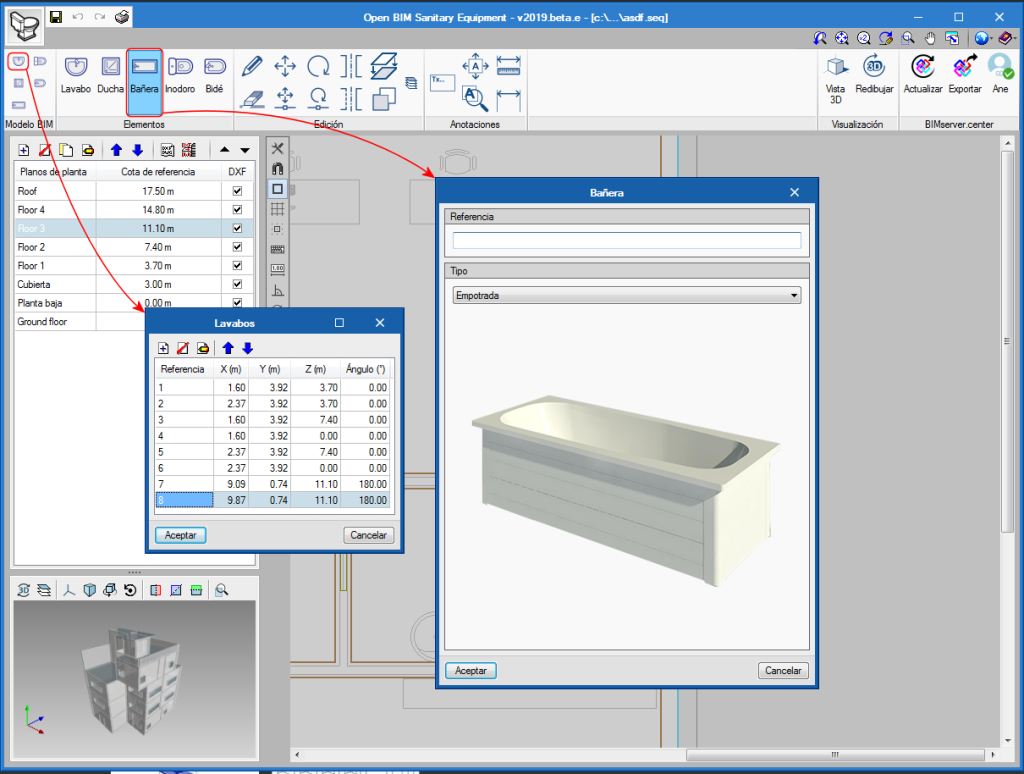
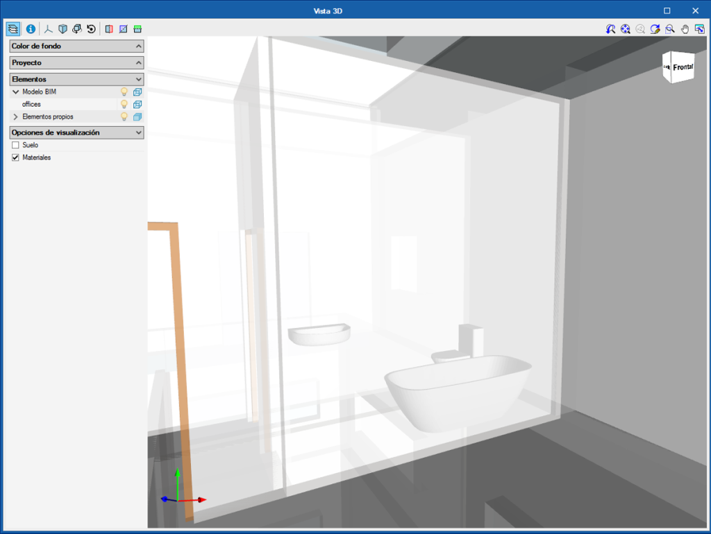
Open BIM Sanitary Equipment is a free tool developed to introduce sanitary equipment of bathrooms and toilets in the BIM model of the project: urinals, showers, bathtubs, washbasins and bidets.
Open BIM Sanitary Equipment exchanges information on the drains of the sanitary equipment with CYPEPLUMBING Sanitary Systems, which implies users save time by not having to introduce this data in the second program. This data can be exchanged thanks to the BIM model of the project that is located on the BIMserver.center platform.
The program provides a detailed list of the sanitary equipment elements of the project, and generates an IFC file with all the attached documents and a GLTF file with the 3D view of the elements that have been introduced. The IFC and GLTF files that have been generated are exported to the BIM model of the project located on the BIMserver.center platform.
CYPEFIRE FDS (new program)
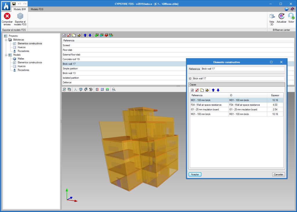
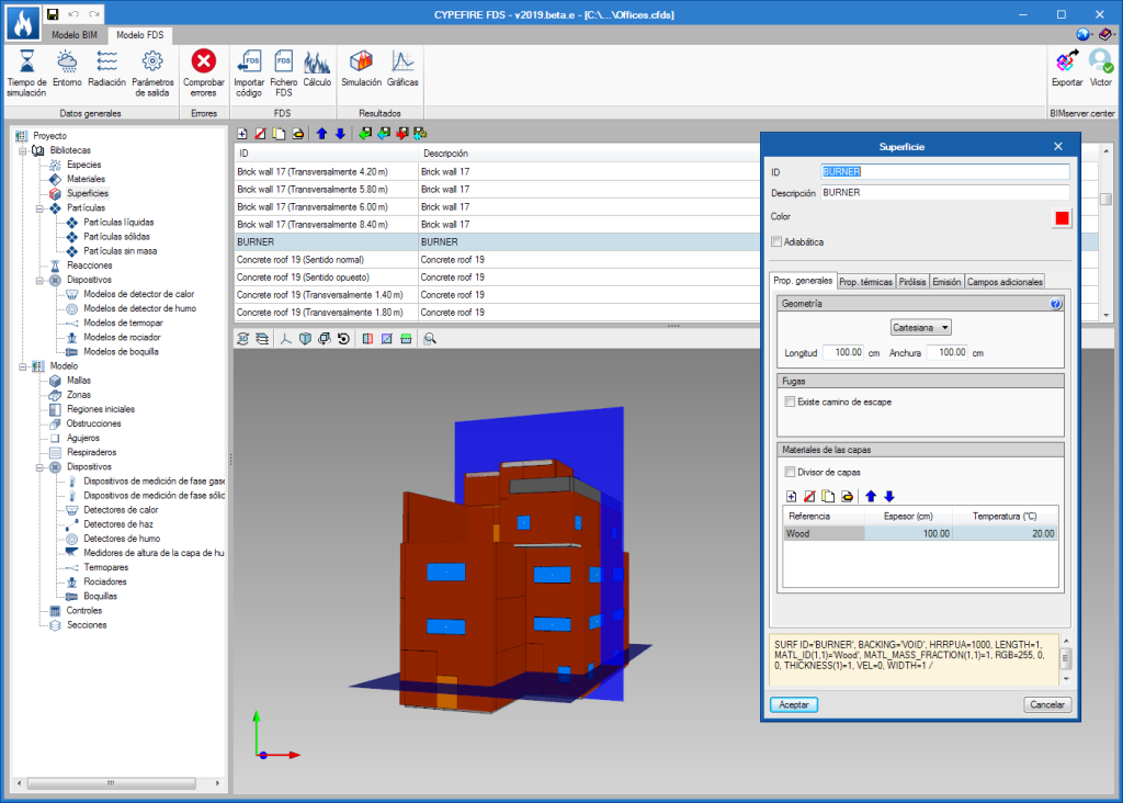
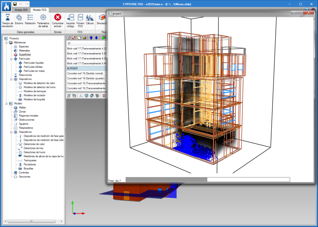
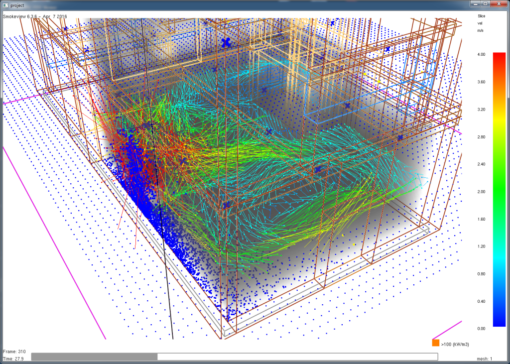
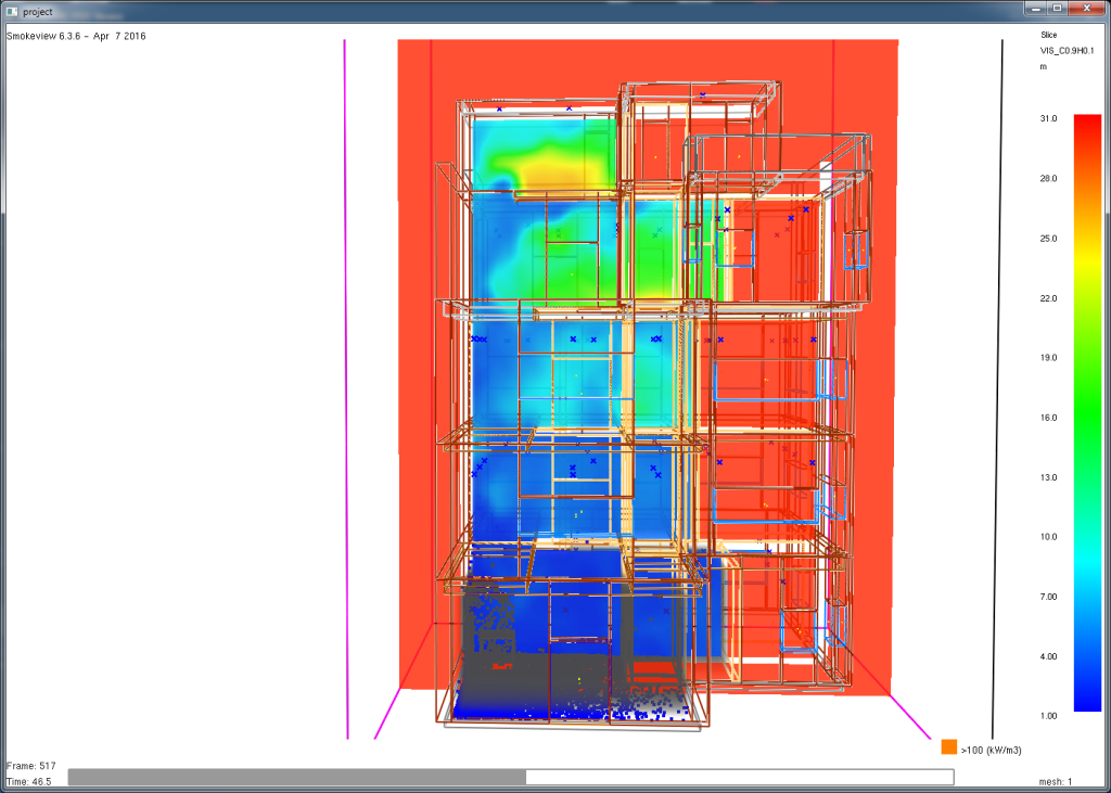
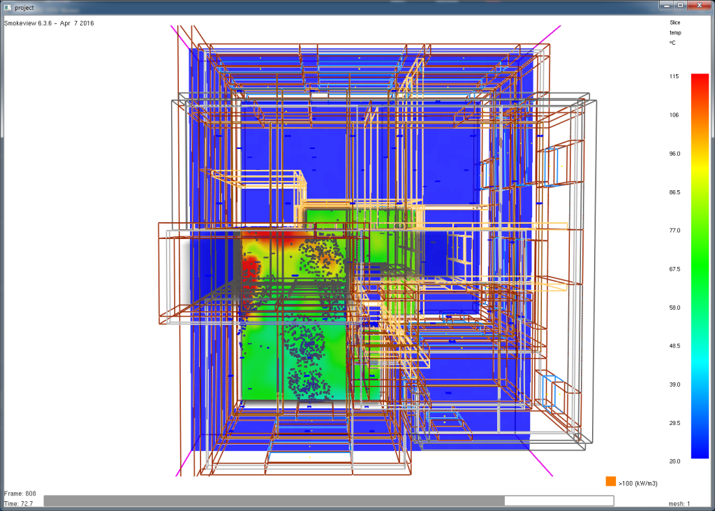
CYPEFIRE FDS is an application for use in the design of complex building models, to carry out simulations of the evolution of fires using the Fire Dynamics Simulator developed by the NIST (National Institute of Standards and Technology, USA).
This application is integrated in the Open BIM workflow using the IFC standard.
CYPEFIRE FDS is a multifunctional tool that can be very useful for firefighter training and for the technicians responsible for the design of the extinguishing systems, temperature control and smoke evacuation systems (SCTEH), to evaluate the fire safety of the buildings during the project stage as well as for the reconstruction of fire scenarios.
With the BIMserver.center web platform, all the participants and applications that are part of an integrated project communicate directly using the Open BIM workflow. This integration is carried out by exchanging IFC information files with a previously defined BIM model.
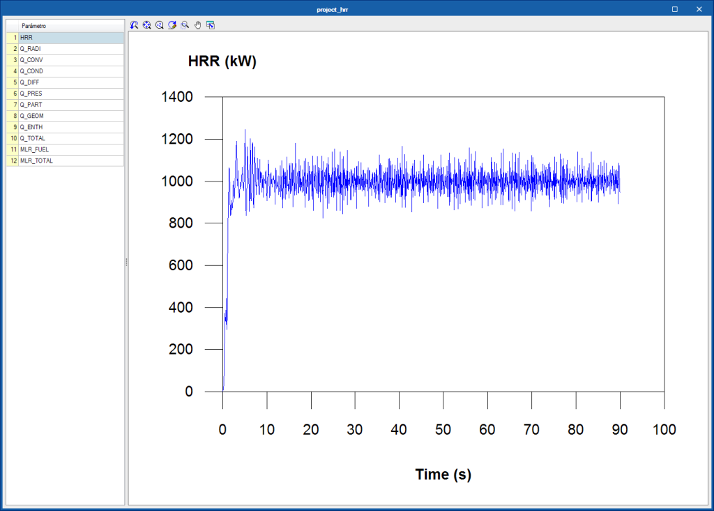
Once the simulation has been carried out using the FDS analysis engine, CYPEFIRE FDS can display the data in several ways, so users can analyse the results in the most efficient way according to their needs:
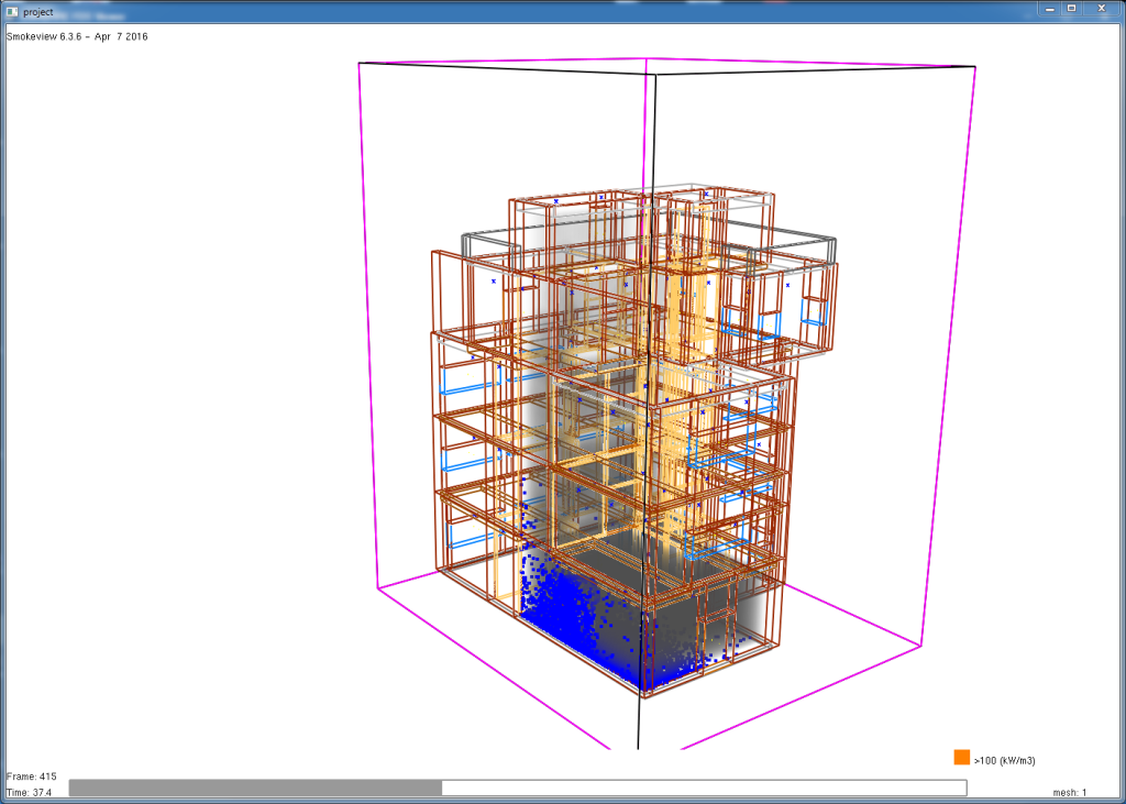
- Smokeview (SMV)
The Smokeview tool, developed by the NIST (National Institute of Standards and Technology, USA) can be launched to view the data of the fire dynamics simulation. - Graphs
During the simulation, the FDS analysis engine writes several files, with CSV format, containing values, obtained as a function of time, of parameters such as the heat emission or status of the devices and controls. The graphs that are generated with this information can be viewed in CYPEFIRE FDS, even during the analysis.
The complexity of performing a fire dynamics simulation in a building and the multiple factors that are involved, require greater hardware and software requirements compared to those that are necessary to carry out normal work with other programs.
To perform the fire dynamic simulation in a building, the CYPE programs user license must include the "Dynamic fire simulation" permit (which is the same that provides access to the "Dynamic fire simulation using the Fire Dynamics Simulator”) and the user license must be updated to the 2019 or higher version.
CYPEFIRE FDS Viewer (new program)
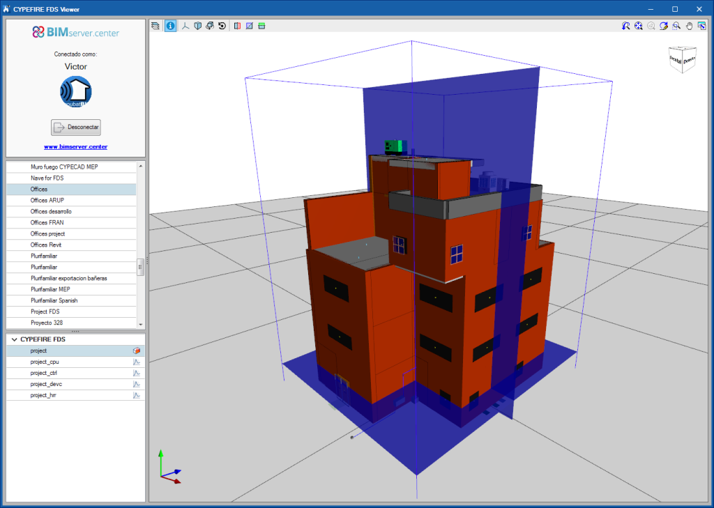
CYPEFIRE FDS is a free application to view simulations of the evolution of fires carried out using the Fire Dynamics Simulator developed by the NIST (National Institute of Standards and Technology, USA).
CYPEFIRE FDS Viewer is integrated into the Open BIM workflow. In order to use the viewer, users must connect to a BIM model located on the BIMserver.center platform. If the selected project contains data from the FDS analysis engine, CYPEFIRE FDS Viewer will interpret the values to display the simulation.
To calculate an FDS model and share the results via the BIMserver.center platform, the Open BIM fire dynamics simulation application, CYPEFIRE FDS can be used (program that has also been implemented in this version).
CYPETHERM Radiant Floor (new program)
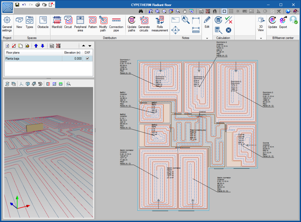
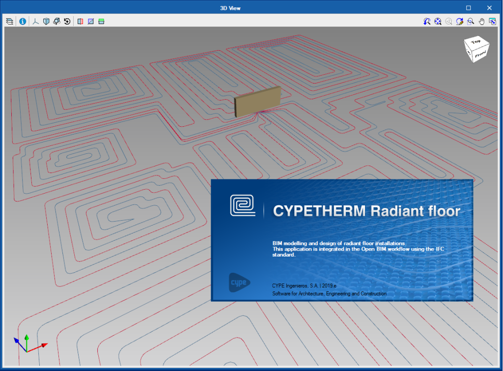
CYPETHERM Radiant floor is a program conceived to design air conditioning systems consisting of generic radiant floors.
It is included in the Open BIM workflow and can be downloaded from the BIMserver.center platform.
CYPETHERM Radiant floor replaces the tools that CYPETHERM HVAC had in previous versions to calculate hydronic radiant floor installations.
To use CYPETHERM Radiant floor, the user license must contain the “Radiant and cooling floor” permit.
More information on this new application will be available shortly.
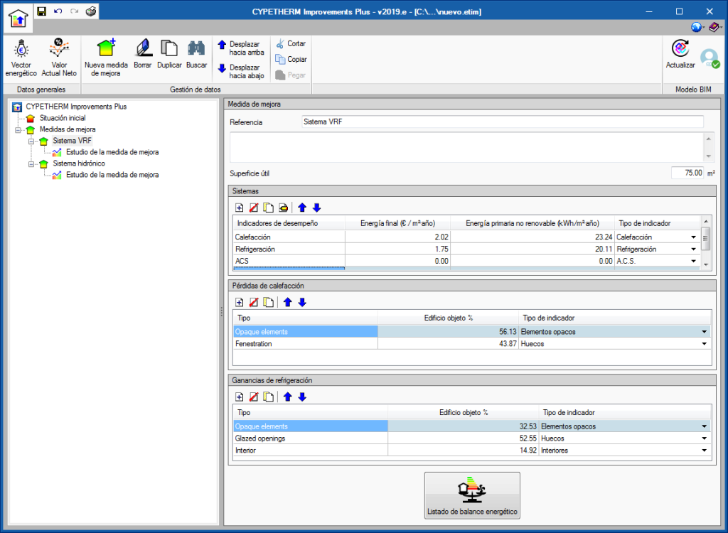
CYPETHERM Improvements Plus (new program)
New program to carry out the energy audit of the building and analysis of possible improvement measures, with energy and economic study of the different alternatives, oriented to the connection with CYPETHERM programs with the EnergyPlus™ analysis engine (CYPETHERM EPlus and CYPETHERM RECS Plus).
This new program is the evolution of CYPETHERM Improvements to optimize the connection of the program that studies the improvement measures with the results offered by CYPETHERM programs with the EnergyPlus™ analysis engine.
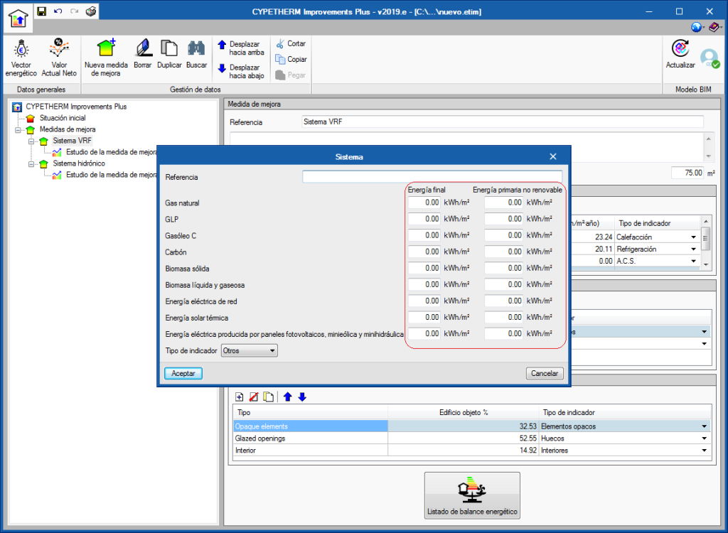
One of the main characteristics that distinguishes "CYPETHERM Improvements Plus" from "CYPETHERM Improvements" is the possibility to describe the energy consumption of the different services of the building, distinguishing the final energy from the primary, non-renewable energy.
To be able to work with "CYPETHERM Improvements Plus" the user license must have the “Improvement measures" permit, which is the same that provides access to "CYPETHERM Improvements".
More information on “CYPETHERM Improvements Plus”.
CYPE Water Supply, Open BIM Sewage, CYPE Electrification, CYPE Gas Supply (new programs)
In the 2019.e version of CYPE software, its "suite" of urban infrastructure programs (Water Supply, Sewage, Electrification and Gas Supply) is included in the Open BIM workflow. From then on, the "suite" can be accessed, as it could until now, from the CYPE program menu (with its classic name); and as programs that can be downloaded from the "BIMserver.center" platform:
- CYPE Water Supply
Can be installed in Spanish, Catalan, French and Portuguese - Open BIM Sewage
Can be installed in Spanish, Catalan, French and Portuguese - CYPE Electrification
Can be installed in Spanish, Catalan and Portuguese - CYPE Gas Supply
Can be installed in Spanish, Catalan, English and Portuguese
Both versions of each type of infrastructure are the same tool, with the same way of working during the introduction, analysis, design and obtaining of the documentation of the installation. The only difference between the classic versions of the infrastructure programs and those that can be downloaded from the BIMserver.center platform, is that in the classic, the connection to a BIM model is optional and those of the BIMserver.center platform must be connected to a BIM model.
Some of the advantages of including the infrastructure programs in the Open BIM workflow are:
- Import the topographic model of the terrain
If an IFC4 file exists in the BIM model, which is located on the BIMserver.center that includes the data of the terrain in an entity of the type “IfcGeographicElement”. - Import the 3D view of other specialties
- Export the documents and 3D view of the installation to the BIM model
- Update the imported information of the BIM model
3D views in CYPE programs
New 3D view system
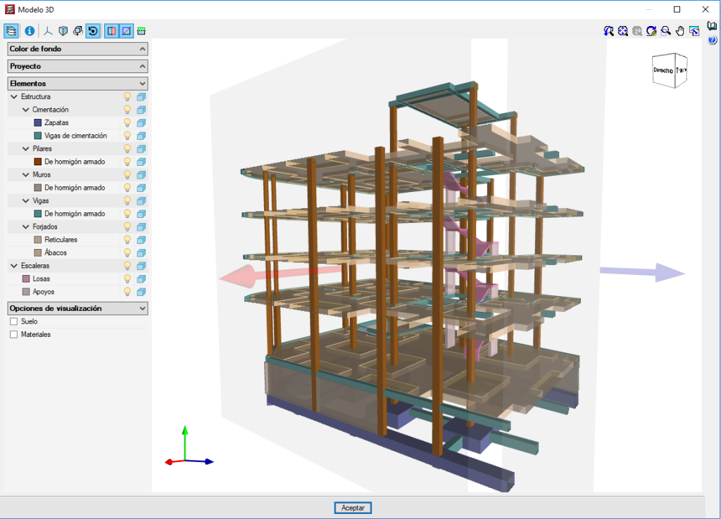
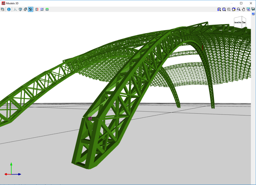
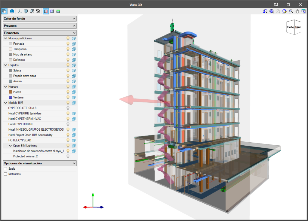
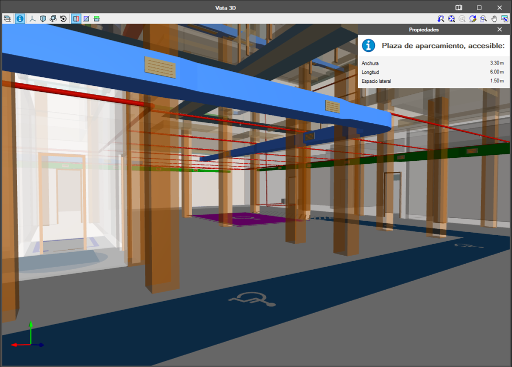
The 2019.e version includes a new 3D view system in most of its programs: CYPECAD, CYPE 3D and the entire family of applications integrated in the Open BIM workflow. It will be incorporated progressively in other programs.
The properties of the system are:
- Improvement in the speed with which scenes containing many objects are drawn
- Dynamic calculation of the rotation pivot of the camera
- Rotation around a point indicated by users
- Possibility to define global section planes X, Y or Z
- Zoom to the object under the cursor in the perspective and orthogonal views
For this viewing system to operate correctly, the applications require a video card that is compatible with OpenGL 3.3 or higher.
Improvements in code application
Acciones en las estructuras. Viento
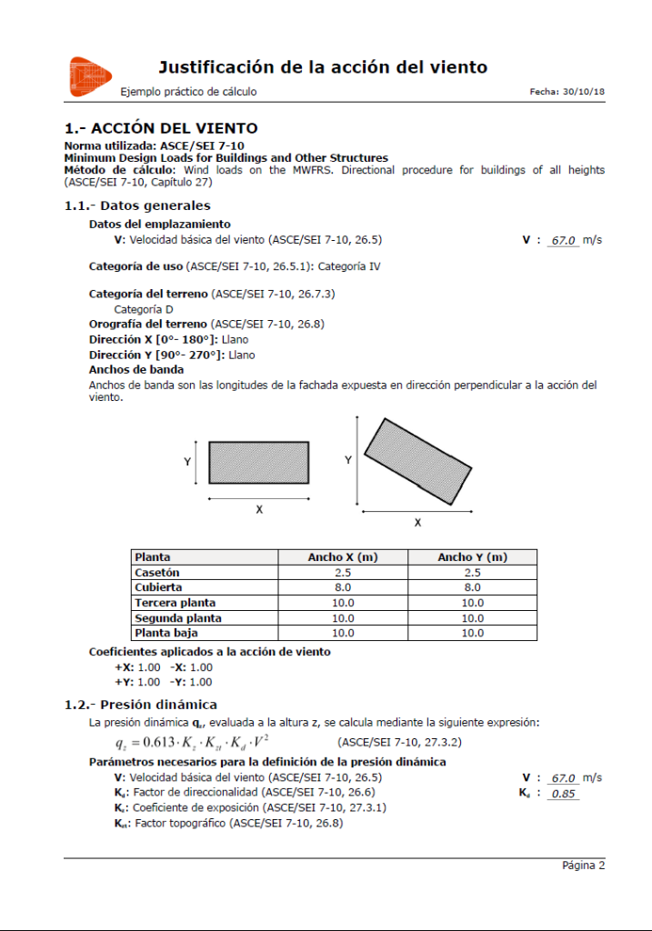
Wind load justification report
The standards for which this report has been implemented can be consulted in the “Wind load justification report” section of the new features of CYPECAD.
CYPE 3D
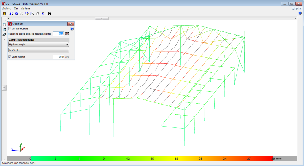
Maximum limit to view values in the deformed shape
As of the 2019.e version, users can set a displacement limit from which the deformed values are not shown.
That is, the deformed shape of the structure is still represented by the scale factor indicated by users regardless of whether the indicated limit is exceeded or not, only now, all the points that exceed the displacement limit are drawn in black.
To do so, the "Maximum value" option has been included in the "Deformed shape" panel that is represented in the "Deformed shape" dialogue.
This tool helps users to visualize the deformed values, discarding the parts with a displacement value higher than that established by them.
This new feature was implemented in CYPECAD in the 2019.d version.
CYPECAD / CYPE 3D
Dimensions in dxf/dwg
As of the 2019.e version, drawings exported in dxf /dwg format will generate “dimension” type element blocks. In previous versions, dimensions on drawings were exported as a series of lines and texts.
CYPECAD
Wind load justification report
In the 2019.e version, a “Wind load justification report” has been implemented for the following codes:
- ASCE/SEI 7-10 Minimum Design Loads for Buildings and Other Structures (USA)
- NB 1225003-1 Acciones sobre las estructuras. Acción del viento. (Bolivia)
- NCh432-2010 Diseño estructural. Cargas de viento. (Chile)
- NSR-10 Capítulo B.6 - Fuerzas de viento. (Colombia)
- NTC-2017 Normas Técnicas Complementarias para Diseño por Viento. (Mexico)
- REP-04 Reglamento para el Diseño Estructural. (Panama)
- REP-2014 Reglamento para el Diseño Estructural. (Panama)
- RNC-07 Reglamento Nacional de Construcción. (Nicaragua)
This report was implemented for other codes in previous versions and will be implemented for other codes progressively.
Infrastructures (Water supply, Sewage, Electrification and Gas supply)
Connection to a BIM model
In the 2019.e version of CYPE software, its "suite" of urban infrastructure programs (Water Supply, Sewage, Electrification and Gas Supply) is included in the Open BIM workflow. From then on, the "suite" can be accessed, as it could until now, from the CYPE program menu (with its classic name); and as programs that can be downloaded from the "BIMserver.center" platform:
- CYPE Water Supply
Can be installed in Spanish, Catalan, French and Portuguese - Open BIM Sewage
Can be installed in Spanish, Catalan, French and Portuguese - CYPE Electrification
Can be installed in Spanish, Catalan and Portuguese - CYPE Gas Supply
Can be installed in Spanish, Catalan, English and Portuguese
Both versions of each type of infrastructure are the same tool, with the same way of working during the introduction, analysis, design and obtaining of the documentation of the installation. The only difference between the classic versions of the infrastructure programs and those that can be downloaded from the BIMserver.center platform, is that in the classic, the connection to a BIM model is optional and those of the BIMserver.center platform must be connected to a BIM model.
Some of the advantages of including the infrastructure programs in the Open BIM workflow are:
- Import the topographic model of the terrain
If an IFC4 file exists in the BIM model, which is located on the BIMserver.center that includes the data of the terrain in an entity of the type “IfcGeographicElement”. - Import the 3D view of other specialties
- Export the documents and 3D view of the installation to the BIM model
- Update the imported information of the BIM model
Import the topographic model of the land
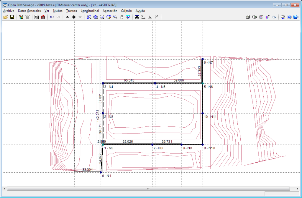
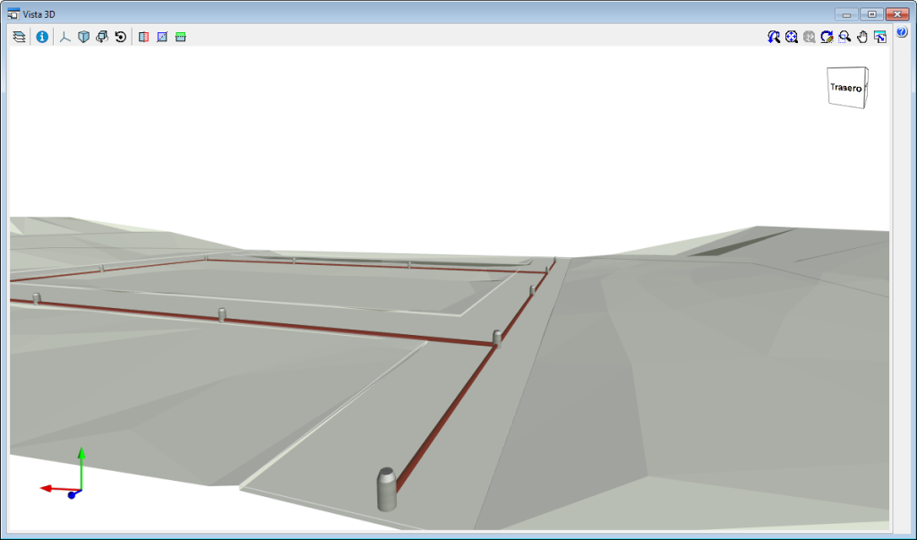
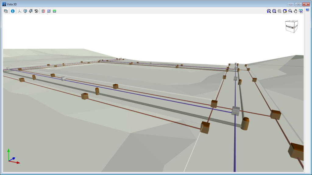
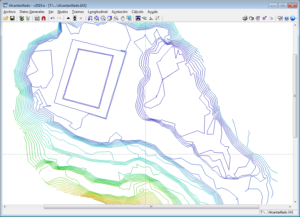
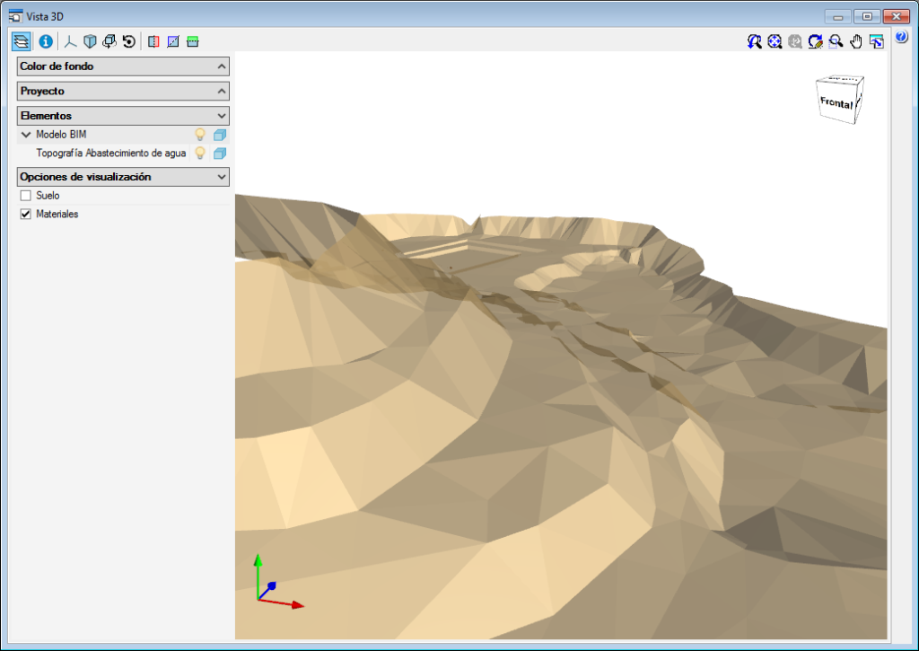
Any of the infrastructure programs (Water Supply, Sewage, Electrification and Gas Supply) can import a topographic model of the land if the project is connected to a BIM model located in BIMserver.center that contains an IFC4 file with the landa data defined in an “IfcGeographicElement” type entity.
If an IFC of these characteristics is imported, the land will appear on the screen represented with contour lines and when the nodes of the network are introduced, the elevation of the land where they are located will be used automatically, greatly aiding in the definition of the network.
If additionally, the geometry of the land is to be visible in the 3D views of the program and in the 3D viewer of BIMserver.center, the IFC4 must have an associated GLTF file that includes that 3D view.
The reading of topographic models of the land is also included in the new equivalent infrastructure programs that are installed from the BIMserver.center platform (CYPE Water Supply, Open BIM Sewage, CYPE Electrification and CYPE Gas Supply).
CYPELEC Networks
Edit, in series, elements belonging to the same class
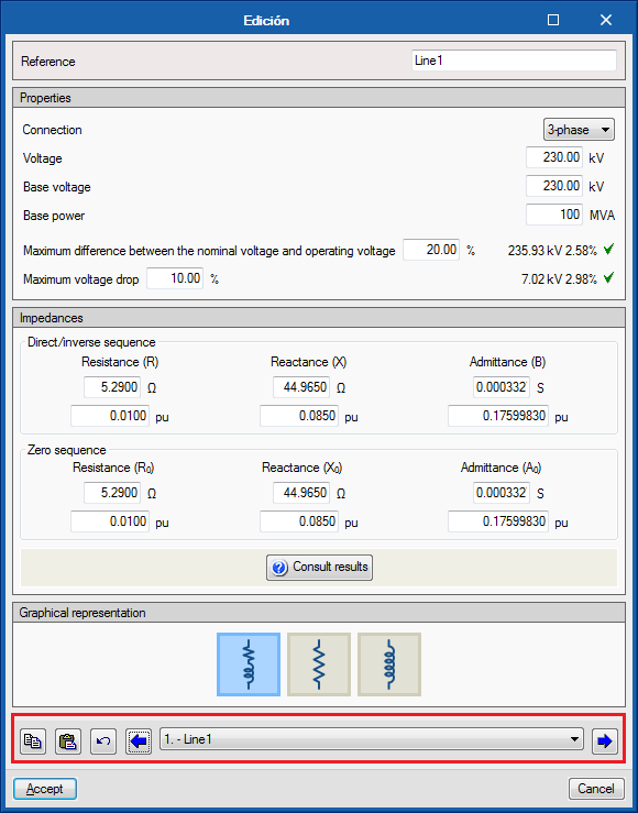
The “Edit series” tool has been implemented to edit, in series, elements belonging to the same category.
The tool is located in the “Edit” section of the toolbar.
If the “Edit series” tool is active when any element of the single-line diagram is edited, for example an impedance, the editing panel that appears has a lower bar that allows to scroll through (backwards and forwards) all the elements of the same category that are present in the single-line diagram. This tool also allows you to copy the editing parameters of the element that is being viewed and paste them onto another previous or subsequent element.
The “Edit series” tool has been created for quicker editing and viewing of the properties of the elements of the circuit diagram.
CYPEPLUMBING Sanitary Systems
CYPEPLUMBING Sanitary Systems
The 2019.e version of “CYPEPLUMBING Sanitary Systems” includes the new features detailed below:
- Representation of excavation volumes in the 3D view
- Graphical analysis of the total excavation per pipe span and per metre
- Longitudinal profile of several consecutive spans of the excavation
- Element reference search in drawings
- Insert elevation as a pipe tag on drawings
More information on these new features of “CYPEPLUMBING Sanitary Systems” will be available shortly.
CYPEPLUMBING Water Systems
The 2019.e version of “CYPEPLUMBING Water Systems” includes the new features detailed below:
- Element reference search in drawings
- Thermal insulation in pipes
- Pressure loss calculation considering the water temperature
- Calculation of heat dissipation in pipes
- Calculation of recirculation flow rates in pipes in return circuits and minimum values
- Graphical analysis of thermal insulation thicknesses, heat flow and pipe temperature
- Insert elevation as a pipe tag on drawings
More information on these new features of “CYPEPLUMBING Water Systems” will be available shortly.
CYPEPLUMBING Solar Systems
The 2019.e version of “CYPEPLUMBING Solar Systems” includes the new features detailed below:
- Element reference search in drawings
- Thermal insulation in pipes
- Insert elevation as a pipe tag on drawings
- Portuguese design code (REH)
- Italian design code (UNI/TS 11300-4)
More information on these new features of “CYPEPLUMBING Solar Systems” will be available shortly.
View photometric curves in the 3D views of the application and in GLTF
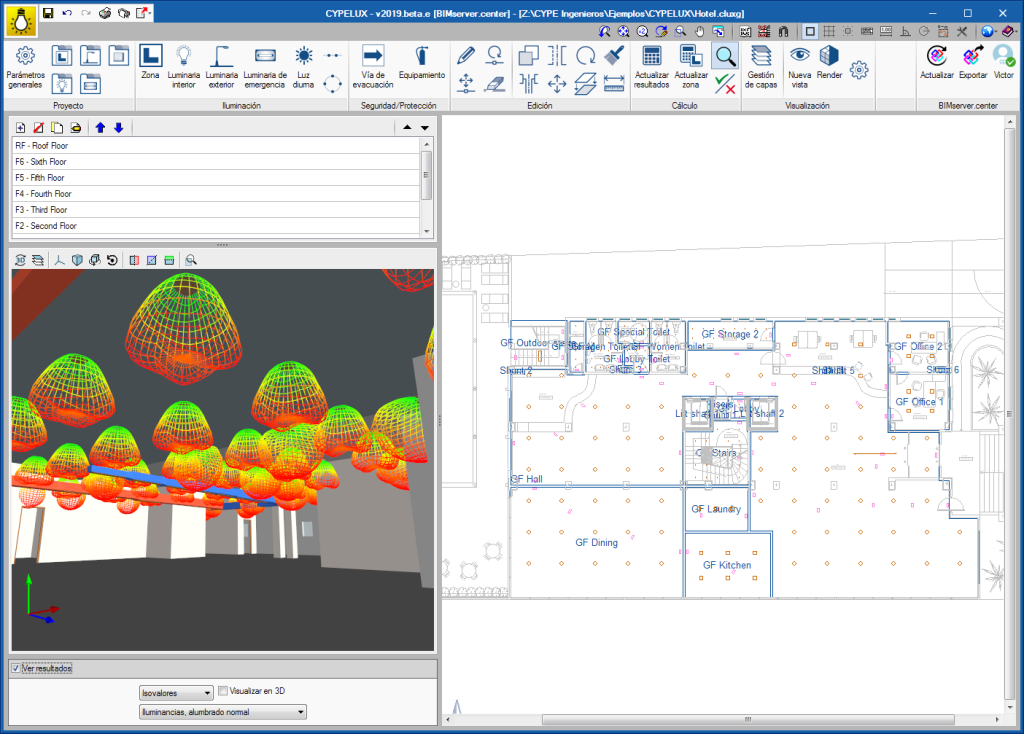
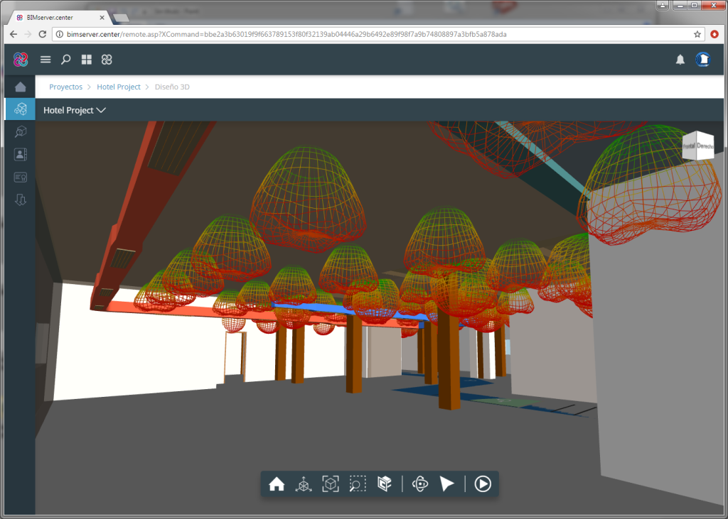
As of the 2019.e version, CYPELUX, CYPELUX CTE, CYPELUX EN and CYPELUX RECS display the photometric curves of the lights used in the project in the 3D view.
Additionally, this information can be included in the BIM model located on the BIMserver.center platform as part of a GLTF file. The user and the different collaborators of the project will be able to visualize the GLTF file with the photometry using the BIMserver.center web viewer or any program that can read GLTF format files.
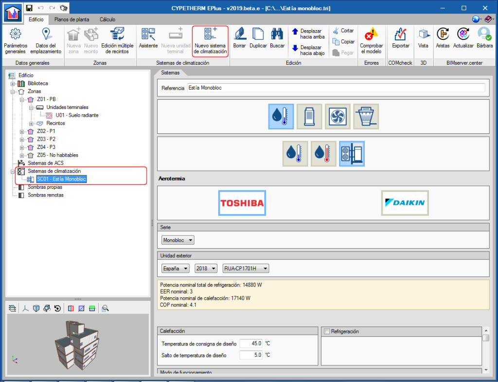
Toshiba EstiaMonobloc aerothermal system
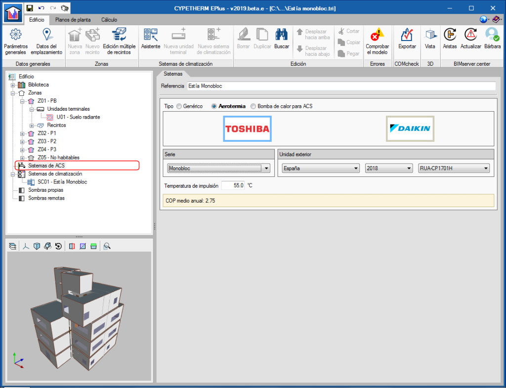
The EstiaMonobloc system, a new system in the 2018 Toshiba catalogue, has been added in the Toshiba aerothermal water-air conditioning systems and in the aerothermal DHW systems.
In the aerothermal air conditioning systems, below the Toshiba logo, users can choose amongst the different outdoor units of the Monobloc series. This equipment must be connected to water-air conditioning terminal units.
If users wish to use an EstiaMonobloc system for air conditioning and DHW, the same outdoor unit model must be selected in both sections (as occurs with the other aerothermal equipment).
Assistant to define air conditioning systems

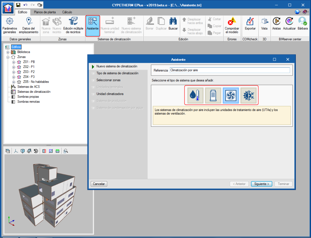
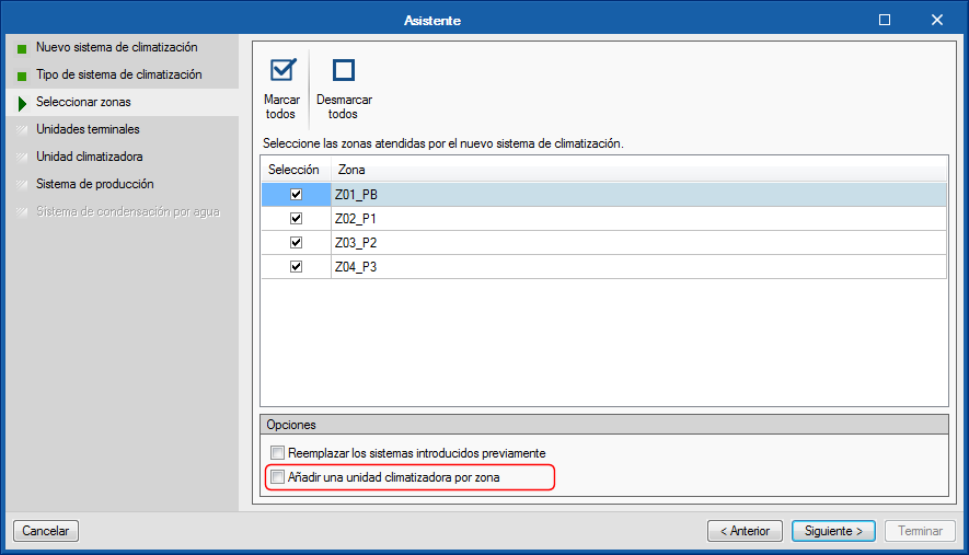
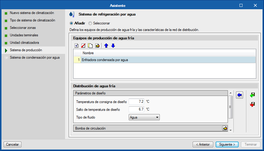
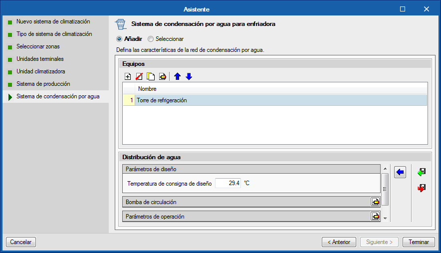
A new tool has been implemented to define the air conditioning systems of the building in a step-by-step way. Using the "Assistant" button, users can create a new complete air conditioning system, or add new terminal units to systems that are already defined in the project. This tool improves the ergonomics of the program, by allowing terminal units to be added and deleted in a single step in the different thermal zones of the building.
When the “Assistant” button of the "Climate control systems" section of the top menu of the program is selected, the window in which the name of the new system is to be provided appears. Users must also choose its typology amongst the water, direct expansion, air or constant performance system categories.
To the left of this window, users can see the steps which the assistant will guide him through to complete the definition of the air conditioning system. The different sections are displayed in black if they must be defined in accordance with the selected options. The buttons on the lower bar allow users to navigate in the assistant.
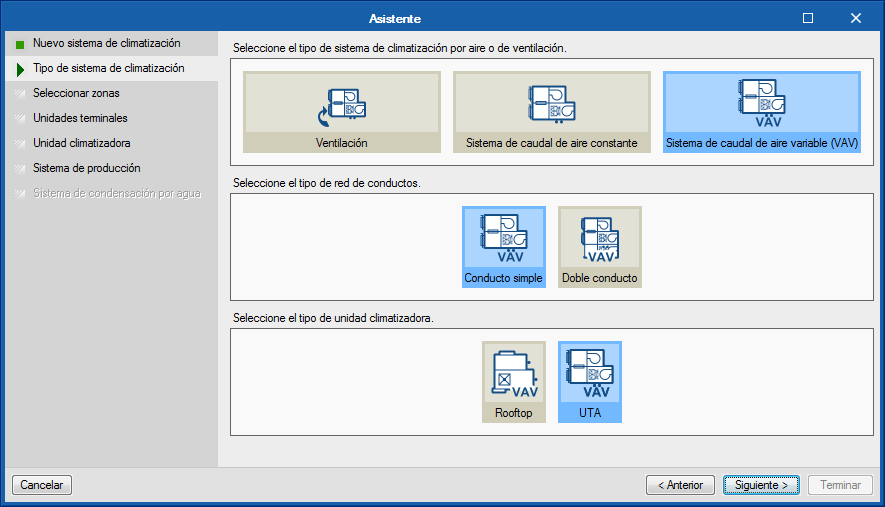
In the second step of the assistant, users must choose the type of air conditioning system, in accordance with the category chosen previously.
In the third step, users must select the areas of the building that will be associated with the air conditioning system. The assistant will automatically create the terminal units of the system defined in each of the selected zones. By default, all these terminal units will be connected to a single production system or to a single air conditioning unit in the case of air conditioning systems. On the other hand, if the option "Add an air conditioning unit per zone" is chosen, the terminal units created in each zone will be connected to their respective system.
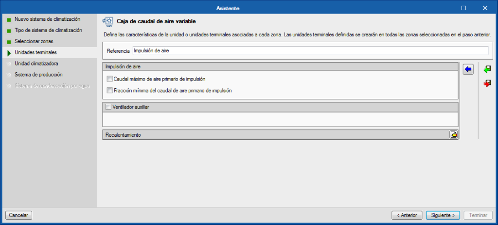
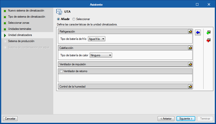
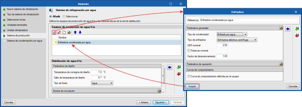
The following steps of the assistant run through the different elements that make up the type of air conditioning system that has been chosen, so users can define its properties. In general, the panels corresponding to the terminal units and air conditioning systems that are available in the program will be shown, as they are required.
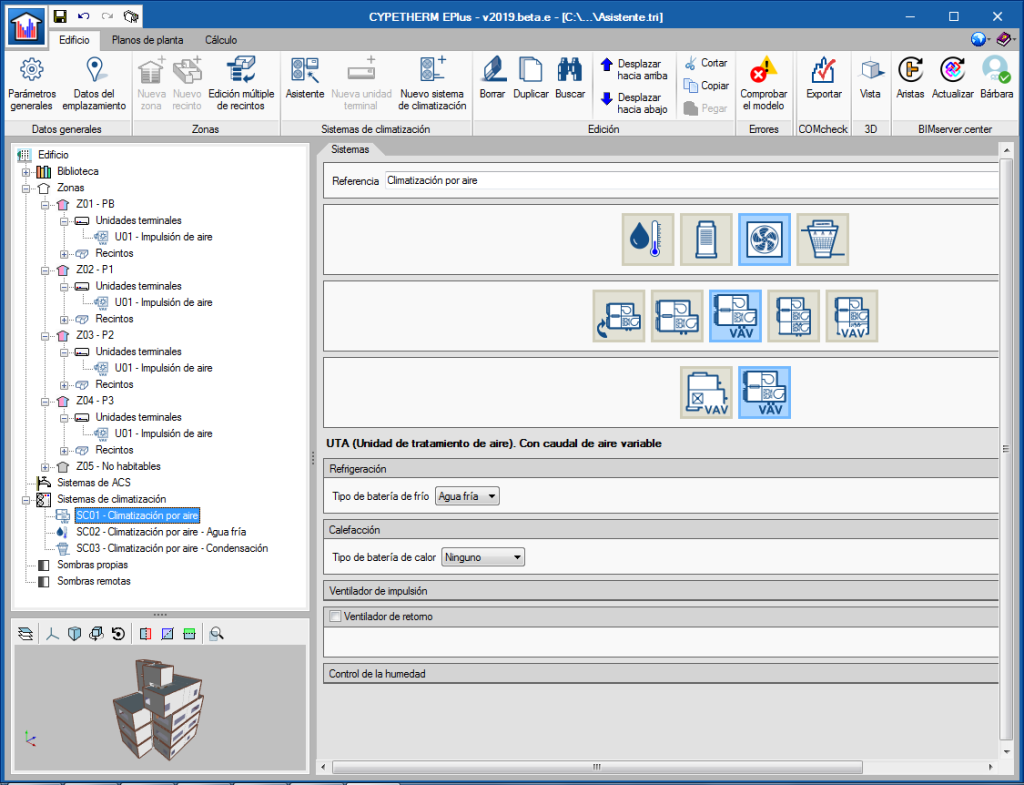
In the images, a variable air flow system has been defined that contains an air conditioning unit with a cold water battery connected to a water-cooled chiller. The assistant successively displays the panels to define the variable flow type box terminal units, the variable flow ATU, the water cooling system the chiller contains and finally, the water condensing system for the chiller. At the end of the wizard, the new elements of the air conditioning system will appear in the diagram of the main screen.
Export to “CYPETHERM Improvements Plus”
As of the 2019.e version, CYPETHERM programs with the EnergyPlus™ analysis engine, CYPETHERM EPlus and CYPETHERM RECS Plus, export the results of the simulation, with the "Improvement measure" option, via the Open BIM workflow to "CYPETHERM Improvements Plus" (implemented in this version). Therefore, they no longer export the results of the simulation to CYPETHERM Improvements.
Import “Open BIM TOSHIBA” equipment
CYPETHERM programs with the EnergyPlus™ analysis engine, CYPETHERM EPlus and CYPETHERM RECS Plus, can import the equipment and pipes introduced in "Open BIM TOSHIBA" (implemented in this version) if they are connected to the BIM project located on the BIMserver platform.
Update to version 9.0 of the EnergyPlus™ analysis engine
The 2019.e version of CYPETHERM programs with the EnergyPlusTM analysis engine uses version 9.0 of the engine, published on 10th October 2018.


