New features

2020.a Version

6 August 2019
Index

New programs

BIMEO2BIMserver (new program)

"BIMEO2BIMserver" is a free tool that allows users to add IFC format files belonging to the "BIMEO" platform to projects located on the "BIMserver.center" platform.

With "BIMEO2BIMserver", "BIMEO" IFC files that have been generated with "AR2BUILD" are also available to BIMserver.center Open BIM projects and are therefore, included in the Open BIM workflow.

"BIMEO2BIMserver" can be downloaded from the BIMserver.center platform and installed in English, French or Spanish.

More information on BIMEO2BIMserver.

Open BIM Layout (new program)

"Open BIM Layout" is a free application designed to compose drawings with views and sections created from BIM models.

The program allows users to create plan views, elevations, sections and axonometric perspectives.

The drawings that are generated using "Open BIM Layout" can be viewed on the BIMserver.center platform by the authorized participants of the BIM project, and so, users have access to all the information from any device and at any time.

"Open BIM Layout" can be downloaded from the BIMserver.center platform and installed in Catalan, English, French, Italian, Portuguese, Portuguese from Brazil or Spanish.

More information on Open BIM Layout.

Open BIM Model Checker (new program)

"Open BIM Model Checker" is a free application designed to analyse and inspect BIM models. The objective of this program is to facilitate the prompt and rapid detection of incidents in models.

The program is integrated in the Open BIM workflow, and so, models of a project located on the BIMserver.center platform can be imported and be part of the collaborative, multidisciplinary and multi-user workflow provided by Open BIM technology.

Any incidents that are generated with the program can be viewed by users in the warnings tab of the "BIMserver.center" platform, providing access to all incident information and requirements from any device and at any time.

Each incident is also displayed in the specialist program that generated the object to which that incident is assigned.

"Open BIM Model Checker" can be downloaded from the BIMserver.center platform and installed in Catalan, English, French, Italian, Portuguese, Portuguese from Brazil or Spanish.

More information on Open BIM Model Checker.

Open BIM Office Furniture (new program)

"Open BIM Office Furniture" is a free application that allows users to introduce a furniture arrangement proposal for office projects.

"Open BIM Office Furniture" has a catalogue with numerous furniture combinations for office building rooms: tables, countertops, desks, chairs, sofas, shelves, storage, refrigerators, microwaves, televisions and computers.

"Open BIM Office Furniture" can be downloaded from the BIMserver.center platform and installed in Catalan, English, French, Italian, Portuguese, Portuguese from Brazil, Spanish, Spanish from Argentina or Spanish from Mexico.

More information on Open BIM Office Furniture.

Open BIM Stairs & Ramps (new program)

"Open BIM Stairs & Ramps" is a free computer tool design to provide the architectural model of stairs and ramps in BIM projects.

Using "Open BIM Stairs & Ramps" users can automatically generate individual stair or ramp spans, or stairwells and ramp cores. The basic units of the program are stair spans, ramp spans, landings and railings. Using these four elements, users can generate the stairs and ramps in an Open BIM project.

"Open BIM Stairs & Ramps" can be downloaded from the BIMserver.center platform and installed in Catalan, English, French, Italian, Portuguese, Portuguese from Brazil or Spanish.

More information on this new application will be available shortly.

StruBIM Design Shear Walls (new program)

"StruBIM Design Shear Walls" is a program to design and check shear walls in accordance with the ACI 318-14 standard.

"StruBIM Design Shear Walls" imports the shear walls and the analysis results from the Open BIM project to which it is connected. From this data, it is possible to design, edit and check the reinforcement of the different shear wall sections. Once the reinforcement design process is complete, the results can be generated and exported. The program offers reinforcement description reports, check reports (summarized or extended) and a 3D view of results, where the resistant sections and interaction surfaces can be viewed.

The program also exports the information required by “StruBIM Rebar” to create the BIM model of the designed reinforcement, to the Open BIM project.

"StruBIM Design Shear Walls" can be downloaded from the BIMserver.center platform and installed in English or Spanish.

More information on StruBIM Design Shear Walls.

StruBIM Rebar (new program)

"StruBIM Rebar" is a program designed to carry out the BIM model of reinforcement in reinforced concrete structural elements.

In this first version, the program imports the information on shear walls and rectangular footings with constant depth, from a BIM project located on the BIMserver.center platform.

Additionally, "StruBIM Rebar" has generation wizards available for the indicated structural elements (so they can be included in the program even if they are not present in the BIM project) and other elements that cannot yet be imported in this first version (strip footings and strap and tie beams).

"StruBIM Rebar" can be downloaded from the BIMserver.center platform and installed in English or Spanish.

More information on StruBIM Rebar.

CYPETEL Schematics (new program)

"CYPETEL Schematics" is an application conceived to analyse and design telecommunications system diagrams.

"CYPETEL Schematics" analyses and designs telecommunications installations, in accordance with design standards or generic specifications, since the checks, the equipment and infrastructure elements can be configured by users. The program allows users to import the values and properties of predefined standards. In the first version of the program, the predefined standards are:

  • Real Decreto 346/2011 (Spain)
  • Manual ITED 3.ª edição (Portugal)
  • Manual ITUR 2.ª edição (Portugal)

"CYPETEL Schematics" can be downloaded from the BIMserver.center platform and installed in English, Portuguese or Spanish.

More information on CYPETEL Schematics.

CYPETEL Systems (new program)

"CYPETEL Systems" is an application to design the infrastructure of telecommunications systems.

"CYPETEL Systems" allows users to design the infrastructure of telecommunications systems in accordance with design standards or generic specifications, since the definition of the infrastructure elements can be configured by users. The program allows users to import the values and properties of predefined standards. In the first version of the program, the predefined standards are:

  • Real Decreto 346/2011 (Spain)
  • Manual ITED 3.ª edição (Portugal)
  • Manual ITUR 2.ª edição (Portugal)

"CYPETEL Systems" can be downloaded from the BIMserver.center platform and installed in English, Portuguese or Spanish.

More information on CYPETEL Systems.

CYPEFIRE Pressure Systems (new program)

"CYPEFIRE Pressure Systems" is an application developed to carry out the checks described in EN 12101-6, which establishes the requirements of a stair overpressure installation.

The application has the System A, B, C, D and E classes that are included in the standard so to perform all the checks that are required for each of them.

"CYPEFIRE Pressure Systems" generates a report for each system, providing details on each system, an estimate of leaks through doors, windows and walls, the flow obtained for each design criteria, etc.

"CYPEFIRE Pressure Systems" can be downloaded from the BIMserver.center platform and installed in Catalan, English, French, Italian, Portuguese, Portuguese from Brazil, Spanish, Spanish from Argentina or Spanish from Mexico.

More information on CYPEFIRE Pressure Systems.

Code implementation and improvements in its application

Concrete structures

Loads on structures. Wind

Loads on structures. Seismic loads

Sound insulation

IFC Builder

View shadows on the 3D model of the building

As of the 2020.a version, in the 3D view of the application, it is possible to show the shadows of the model and those produced by adjacent buildings. This new functionality is available in the “Shadows” group, in the left side menu of the 3D Views window.

When the shadow view is activated, they are projected onto the buildings represented in the 3D view and on the ground (if it is included in the 3D view).

The location of the project must be indicated by stating its “Orientation” and its “Latitude”. By default, the orientation will be obtained from the project (Project > Project > Orientation) although it is possible to modify it in the 3D view.

Users can choose the solar time and any day of the year on which the shadows are to be reproduced, as well as show the position of the sun and its trajectory.

It is also possible to represent an animation of the 3D view in which the daily variation of the shadow is observed every day of the year at the selected time. The animation can be stopped at any moment, allowing users to view the shadows that are cast at any time and day of the year.

Plugin Open BIM – Revit

View requirements and incidents of the Open BIM project

As of the 2020.a version, the "Plugin Open BIM - Revit" allows users to view the incidents and requirements of BIM Open projects of the BIMserver.center platform in Revit.

To do so, an "Incidents" section has been implemented in the plug-in. From this new section of the plug-in, users can consult the name, date, author, description and an image of the requirements and incidents.

By double clicking on one of the incidents that appears in the new section, Revit will show the element to which the incident refers to in the active window, which helps to easily detect the error in the project.

Open BIM Carpentry

Reading and editing of doors and skylights

As of the 2020.a version, the "Open BIM Carpentry" application imports doors and skylights, which allows users to completely define the carpentry of the building in the BIM model.

Open BIM Residential Furniture

Open BIM Water Equipment

CYPECAD

Open BIM workflow

Management of the connection with Open BIM projects

In the 2020.a version, different tools have been implemented to manage the connection with Open BIM projects on the BIMserver.center platform.

In previous versions, a CYPECAD project was only linked to an Open BIM project on the BIMserver.center platform if the project had been started by importing a BIM model, which could not be unlinked. As of the 2020.a version, the new tools also users to link an existing CYPECAD project to an BIMserver.center Open BIM project and unlink it at any time.

The tools to manage the connection with an Open BIM project are grouped in the BIMserver.center menu. Some already existed in previous versions and others have been implemented in the 2020.a version:

  • Link
    This tool allows users to connect a project to a new or existing BIMserver.center project. When a project is linked to a BIMserver.center project, users can export the results, as well as import the 3D views from other technical fields that will be displayed in the 3D view of the BIM model.
  • Unlink
    This tool allows users to unlink a project from a BIMserver.center project.
  • Import (available since the 2018.c version)
    Unlike the "Link" tool, the "Import" tool reads the architectural model of the linked project and generates floors, columns, floor slab outlines and construction elements. It is only available when no new floors have been created.
  • Consult
    This tool allows users to check the status of the IFCs that are present in the linked Open BIM project and update them. The design model in CYPECAD does not undergo any changes during the update. "Consult" is available when the project has been linked to an Open BIM project after it has been created.
  • Update (available from previous versions)
    This tool operates differently if the CYPECAD project has been connected to a BIM project since its creation or if it has been connected later on.
    • If the CYPECAD project has been linked to a BIM project from the start
      This tool updates the design model and the BIM models of the other fields of the project that are represented in the 3D view of the BIM model in CYPECAD.
    • If the CYPECAD project has been linked to a BIM project after its creation
      This tool only updates the BIM models of the other fields of the project that are represented in the 3D view of the BIM model in CYPECAD.
  • Export (available from previous versions)
    Exports the information generated by CYPECAD to the linked BIMserver.center platform project.

Export the animation of the deformed shape to the BIM model

In the 2020.a version the animated 3D views of the deformed shape can be exported. To do so, users have to mark the type of loadcase for which the deformed shape is to be exported in the panel that appears when the information generated by CYPECAD is exported to the Open BIM project, and define an amplification factor. This way, the IFC that is generated during the export will include the GLTF files that contain the different 3D views. The 3D views of the deformed shapes can be consulted in the BIMserver.center platform viewer.

Shear wall design

In the 2020.a version the design of the shear walls from a CYPECAD project has been implemented. The design process begins in CYPECAD where the shear walls are defined and the analysis of the structure is carried out. Then, the shear walls and their forces are imported in in StruBIM Design Shear Walls to design the reinforcement. Finally, the 3D model of the reinforcement is created in StruBIM Rebar. "StruBIM Design Shear Walls" and "StruBIM Rebar" are two new applications that have been implemented in the 2020.a version. These applications and CYPECAD are integrated in the Open BIM workflow.

Introduce or assign shear walls

In the 2020.a version of CYPECAD, there are two ways to assign “shear wall” properties to reinforced concrete walls and plane stress walls.

  • During the introduction of the wall
    When a reinforced concrete wall or plane stress wall is introduced in CYPECAD, the "Shear wall" option can be activated in the panel that appears on the screen, and a tag can be assigned. All the walls that have the same tag are grouped together to make up a shear wall.

  • Assigning the properties to a wall that is already introduced
    In the "Walls" menu of CYPECAD, an option has been implemented to assign the shear wall properties and a tag to walls selected by users. Only reinforced concrete walls and plane stress walls can be selected.

Walls that have been assigned the same tag will be represented with the same colour and make up a shear wall.

Shear walls intervene in the force analysis of CYPECAD, but are designed in StruBIM Design Shear Walls.

3D view of shear walls

A 3D view for shear walls has been implemented. The option can be accessed from the "Walls" menu. The shear walls of the structure are represented in this view and are drawn in a different colour depending on the type of shear wall (walls that are introduced with the same tag are grouped and so, have the same colour). The tag that has been assigned to each shear wall can be consulted in this 3D view.

Export and design in StruBIM Design Shear Walls

To design the reinforcement of the shear walls that have been defined in CYPECAD, the project must be linked to an Open BIM project on the BIMserver.center platform. In CYPECAD, once the shear walls have been defined and the structure has been analysed, the BIM model that is created by CYPECAD must be exported. This is when the information, as well as other data in open format, that "StruBIM Design Shear Walls" requires to design the shear wall reinforcement is generated.

Shear wall forces report

A section on shear wall forces has been included in the “Forces and reinforcement of columns, shear walls and walls” report that is generated by CYPECAD. This section will appear when shear walls have been defined in the project. The forces are displayed in the general axes and referred to the centre of gravity of the group of walls that make up the shear wall.

CYPELEC Electrical Mechanisms

Customize symbols

As of the 2020.a version of "CYPELEC Electrical Mechanisms" users can create customized symbols for the elements of the installation.

To do this, the "Symbols" button has been provided in the "General options" menu, which allows users to create new symbols, and then assign them to an element of the installation.

CYPELEC CORE

Export drawings to the BIM project

As of the 2020.a version, users of CYPELEC Core, CYPELEC REBT, CYPELEC NF and CYPELEC RETIE can export drawings to the BIM project to which they are linked on the BIMserver.center platform.

CYPEPLUMBING Sanitary Systems / CYPEPLUMBING Water Systems / CYPEPLUMBING Solar Systems / CYPEHVAC Hydronics

New editing tools

New editing tools have been added to the toolbar:

  • Move element
    Moves the selected element and disconnects it previously from the pipe.
  • Move span
    Allows users to only move spans and disconnects it previously them from the elements to which they are connected.
  • Rotate element
    Rotates the selected element and disconnects it previously from the pipe.

Improvements in the 3D view

The 3D views of the plans that are generated can be configured in different ways:

  • In colour, without marked edges
  • In colour, with marked edges
  • Monochrome, with marked edges

CYPEPLUMBING Water Systems / CYPEPLUMBING Solar Systems / CYPEHVAC Hydronics

Introduce the weather data by selecting it on a map

In previous versions, the introduction of weather data by selecting it on the map was already available for certain countries. Now, this selection is also possible for France.

The data that is automatically entered when an area is selected on the map is:

  • In CYPEPLUMBING Water Systems
    The outside temperature and cold water temperature data of the network that is required to calculate the energy dissipation in the pipes, the water temperature and recirculation flow rates.
  • In CYPEPLUMBING Solar Systems
    The data of the outside temperature, cold water temperature of the network and solar irradiation that is required to calculate the energy dissipation in the pipes, to calculate the temperature of the water in the network and the solar energy contribution.
  • In CYPEHVAC
    The outside temperature data that is required to calculate the energy dissipation in the pipes and to calculate the temperature of the water.

CYPEPLUMBING Sanitary Systems / CYPEPLUMBING Water Systems

3D animation in the direction of the flow

In the 3D view of "CYPEPLUMBING Sanitary Systems" and "CYPEPLUMBING Water Systems" an animation of the direction of the water flow can be seen. The velocity of the animation is proportional to the velocity of the water in each span.

Automatic selection of design criteria

As of the 2020.a version, CYPEPLUMBING Sanitary Systems and CYPEPLUMBING Water Systems can carry out the automatic selection of the design criteria for horizontal pipes in all the zones of the installation.

To do so, the “Design criteria” option has been implemented in the “Design options” dialogue, which users can activate or deactivate. By default, existing projects from previous versions will have this option deactivated and in new ones, it will be activated.

This automatic design criteria selection can be configured by users.

If the design criteria are not to be assigned to a specific span during the design process, users must select the span and block the automatic assignment of the design criteria by clicking on the design criteria padlock.

CYPEPLUMBING Sanitary Systems

Slope indication on drawings

In previous versions of the program slopes were indicated on drawings using the percentage symbol (%). Now the slope can be represented using the text "/ 100".

CYPEPLUMBING Water Systems

AcouBAT by CYPE

Code implementation: CTE DB HR (Spain)

As of the 2020.a version, AcouBAT by CYPE allows users to import the configuration of the acoustic limits contained in the document “DB HR Protección frente al ruido” of the “Código Técnico de la Edificación” of Spain. To automatically provide the acoustic requirements with the values of the standard, users must indicate the "Use of the building", the "Type of predominant outside noise" and the "Day noise index (Ld)".

Open BIM Lightning

Improvements in the 3D environment of the application

As of the 2020.a version, "CYPE Lightning" has begun to use a new 3D work environment with significant visual and functional improvements in the application. To adapt the user interface to this implementation, the "View" tab has been added to the toolbar of the program and the list of floor plans has been transformed in the view navigator.

Now users can generate different total or partial representations of the building model. These will be added to the view navigator located on the left side of the work area. It is important to note that the views are not linked to the data structure of the project, so that they can be created, modified and deleted without affecting the underlying model.

Each view has several associated configuration parameters, such as the range of vision and the level elevation, which vary depending on the type of view. In this version the following types of views are available:

  • Floor plan
    Floor plans are representations of the building on a horizontal plane viewed from above.
  • Ceiling plan
    Ceiling plans, like the floor plans, are representations of the building on a horizontal plane but, in this case, seen from below.

  • Elevation
    Elevation views are representations of the building on a plane that is perpendicular to the horizontal plane of the project.

  • Section
    Section views are cuts of the building that are perpendicular to the horizontal plane of the work.

  • Generic plan
    In a generic plan, the view is generated from a plane that is located anywhere in the space.

  • Vista 3D
    Users can create several 3D representations of the model with different visibility options and camera positions.

Finally, the "Object snap options" panel has been modified so users can modify the visibility and references to objects of the project elements independently. This way, the components of the design model can be superimposed with those of the digital model of the building defined in the BIMserver.center platform project using other Open BIM tools.

CYPEHVAC Schematics

Symbol drawing tool

Sometimes users may wish to represent an element of the diagram with a symbol that is different from the default symbol that comes in the ASHRAE database. This may be due to several reasons: customer requirements, to continue with the symbols used in a rehabilitation project or the designer's own custom.

As of the 2020.a version, it is possible to design symbols and assign them to elements.

Colour and path of pipes, and tool to copy format

As of the 2020.a version of "CYPEHVAC Schematics", users can customize the colour and appearance of the lines of the pipe paths.

Furthermore, with the new "Copy format" tool, the same properties can be assigned to other elements (colour, line type, flow, temperature).

CYPEHVAC Ductwork

Diffusers

As of the 2020.a version, diffusers can be introduced in duct installations.

In the "Air terminals" section of the toolbar, the "Discharge diffuser" button has been implemented with which users can introduce diffusers in the installations. As occurs with the rest of the elements, the program contains a default library and users have the possibility to create their own library using the import/export options.

CYPETHERM EPlus

Compatibility improvements of air conditioning systems

As of the 2020.a version, more than one condensation system can be defined for reversible heat pumps in the project. Furthermore, the terminal unit of the "Water-air heat pump" can be combined with other terminal units in the same thermal zone, except with air conditioning terminal units connected to air conditioners.

Similarly, it is possible to combine "Constant performance equipment" type terminal units with other terminal units in the same thermal zone, except with air conditioning terminal units connected to air conditioners.

New options in the constant performance equipment: power and programming

An option has been added to define the heating and/or cooling power of "Constant Performance Equipment" type terminal units. If the power is not specified, the equipment will overcome the thermal load of the area where it is located, according to the activation sequence of the terminal units defined in the area.

Furthermore, the equipment operation schedule can be defined. Users can choose the equipment that is always available to overcome the load, as until now, or establish an operating schedule.

VAILLANT fan coils

The VAILLANT "aroVAIR" fan coils catalogue has been implemented. Within the Fan coil-type water air conditioning terminal units, the VAILLANT logo appears. In the panel that opens when the logo is clicked on, users can choose amongst the different fan coil types and models this manufacturer has to offer. The equipment is fully defined in the program.

Fan coils must be connected to a water air conditioning system, either of the water distribution type or of the aerothermal type. They are compatible with the water production equipment of all the other manufacturers.

SAUNIER DUVAL fan coils

The SAUNIER DUVAL "Genia Fan" fan coils catalogue has been implemented. Within the Fan coil-type water air conditioning terminal units, the SAUNIER DUVAL logo appears. In the panel that opens when the logo is clicked on, users can choose amongst the different fan coil types and models this manufacturer has to offer. The equipment is fully defined in the program.

Fan coils must be connected to a water air conditioning system, either of the water distribution type or of the aerothermal type. They are compatible with the water production equipment of all the other manufacturers.

SAUNIER DUVAL DHW heat pumps

The catalogue of heat pumps for domestic hot water production (DHW) "Magna Aqua" by SAUNIER DUVAL has been added. Within DHW Systems, when “Heat pump for DHW” is selected, the SAUNIER DUVAL logo appears. By clicking on it, users can choose amongst the different models the manufacturer has to offer.

The specifications of these devices depend on the type of weather selected in "SPF climatic conditions", within the "Location data" panel.

CYPETHERM LOADS / CYPECAD MEP

ASHRAE weather database update

The ASHRAE weather database has been updated to “Weather Data Viewer” version 6.0. This database has 8118 stations located throughout the world, included in 2017 ASHRAE Handbook, and is available in CYPECAD MEP, CYPETHERM LOADS, Open BIM TOSHIBA, Open BIM DAIKIN, Open BIM FUJITSU and Open BIM MIDEA.

Arquimedes. Bill of quantities of Revit models

The section “RVT links” is added to the Revit entities tree

When the Revit BIM model that is linked to Archimedes contains Revit links, the "RVT Links" section appears in the Revit entities tree. This section aids users to obtain quantities and to make comments in the quantity tables of the selected Revit link.

A new zone called "Links" is also included in the "Quantity filters" option that appears when the new zone button is pressed. In the "Links" area users can mark, to "Show" or "Measure" Revit links to see the number of instances that contain the links and to activate the option "Detail elements" in the quantity tables, depending on the composition of the comments that is defined.

Option improvements for the option “Deduct openings greater than...”

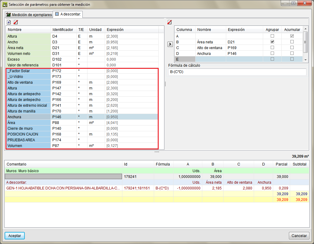
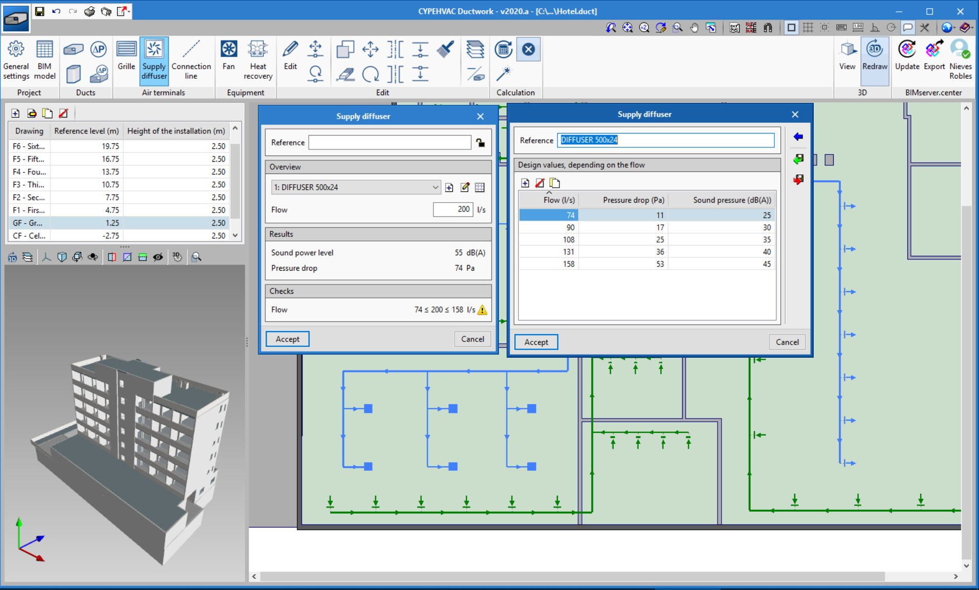
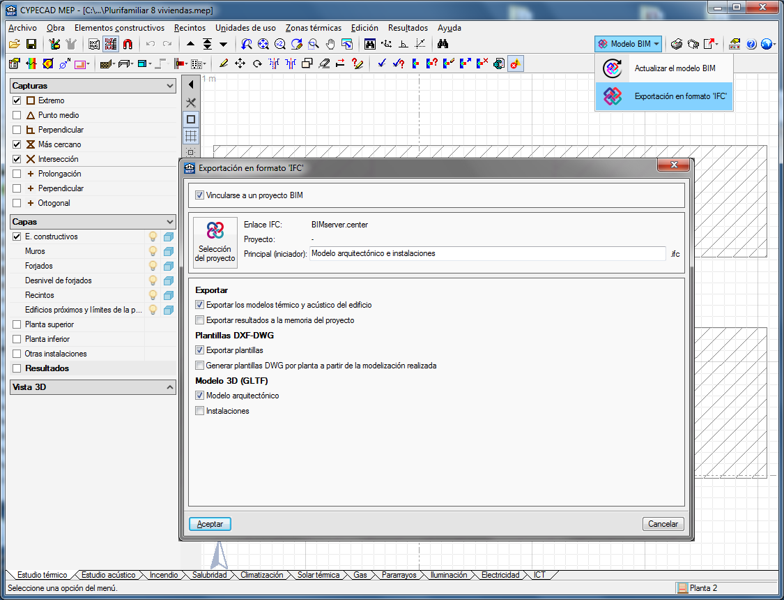
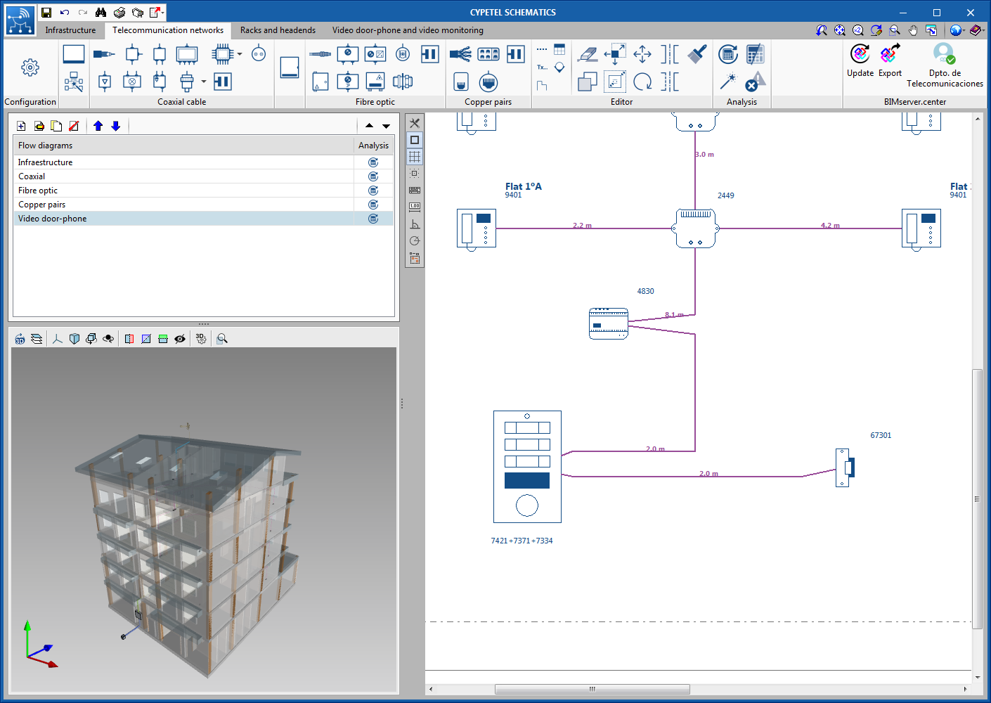
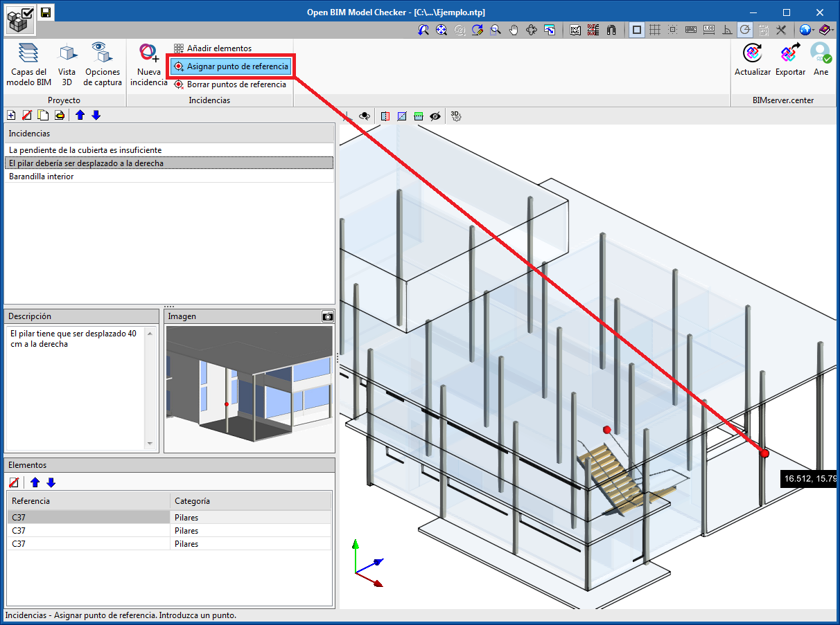
The number of fields available for openings measurements and for measurements of elements that use a material have been increased.

When a Revit entity or material with the possibility to have openings deducted is linked to a budget item in Arquimedes, all the numerical parameters of elements and material quantities that produce openings are made visible in the “To deduct” tab, when the option “Deduct openings greater than...” is activated. For example, in a "Wall", both the dimensions of openings provided by the Revit complement and the numerical parameters of the elements that produce openings (windows, doors, etc) are shown in the "To deduct" tab.