New features

2024.d Version

22 November 2023
Index

New programs or modules

Bars only in tension (new CYPE 3D module)

In version 2024.d of CYPE 3D, non-linear analysis has been implemented so that elements with non-linear behaviour can be considered. One such element is a bar that works only in tension. This analysis is carried out by means of the "OpenSees analysis engine".

The non-linear analysis of bars working only in tension is part of the new CYPE 3D module "Bars only in tension". In order to be able to use this module, the program license must include the permission required to use it as well as the permission to use the "OpenSees analysis engine".

In CYPE 3D's new feature “Non-linear analysis to consider "Bars only in tension" and "Uplift at supports" (new modules)” more information on non-linear analysis, on this module and on another new CYPE 3D module, which also performs non-linear analysis for supports with uplifts, can be found.

Uplift at supports (new CYPE 3D module)

In version 2024.d of CYPE 3D, non-linear analysis has been implemented so that elements with non-linear behaviour can be considered. These elements include supports with uplifts. This analysis is carried out by means of the "OpenSees analysis engine".

The non-linear analysis of supports with uplifts is part of the new CYPE 3D module "Uplift at supports". In order to be able to use this module, the program license must include the permission required to use it as well as the permission to use the "OpenSees analysis engine".

In CYPE 3D's new feature “Non-linear analysis to consider "Bars only in tension" and "Uplift at supports" (new modules)” more information on non-linear analysis, on this module and on another new CYPE 3D module, which also performs non-linear analysis for supports with uplifts, can be found.

Buckling analysis (global stability) (new CYPE 3D module)

As of version 2024.d, users can carry out the linear buckling analysis. The linear buckling analysis allows the critical load factors and the buckling deformations of the structure to be determined for each analysed combination by solving an eigenvalue problem.

In order to carry out this analysis, the user's license must have the necessary permission for this module and for the "OpenSees analysis engine".

Further information on this new module can be found in the CYPE 3D new feature "Buckling analysis (global stability)".

Open BIM Signs (new program)

As of version 2024.d, the new Open BIM Signs application is now available. This program is designed to provide signage solutions for any type of building using the various manufacturers included in the manufacturers' library.

Open BIM Signs can collect the sign requirements for fire protection, evacuation and accessibility elements, requirements generated by CYPEFIRE and CYPE Accessibility, respectively.

The application's connection to the manufacturers' catalogue allows the download and use of the complete manufacturers' catalogue as well as subsequent updates.

Open BIM Signs can be installed in Catalan, English, French, Portuguese and Spanish. In order to use it, users must have the corresponding permission for this program.

Open BIM Cable Routing (new program)

Open BIM Cable Routing is a program designed for the BIM modelling of cable routing systems. By means of a three-dimensional work environment, the tool enables the spatial layout of manufacturers' solutions for cable routing.

In order to help users design and distribute cable routing, the program incorporates technical information for cables from different manufacturers, both electrical and telecommunication cables. The program can also read information from the single-line diagram of the electrical system designed in programs such as CYPELEC REBT or CYPELEC Core.

Open BIM Cable Routing can be installed in Catalan, English and Spanish. In order to use it, users must have the corresponding permission for this program.

Implementing codes and improving their enforcement

Concrete structures

Implementation of national annexes to Eurocode 2 (EN 1992) in CYPE Connect and StruBIM Steel

In version 2024.d of CYPE Connect and StruBIM Steel, the national annexes to Eurocode 2 have been added for the following countries:

  • EN 1992-1-1 (Design of concrete structures. Part 1-1: General rules and rules for buildings)

    • Bosnia and Herzegovina
      BAS EN 1992-1-1/NA:2019

    • Sri Lanka
      SLS EN 1992-1-1:2013/NA

  • EN 1992-4 (Design of concrete structures. Part 4: Design of fastenings for use in concrete)

    • Bosnia and Herzegovina
      BAS EN 1992-4/NA:2021

Rolled and welded steel structures

Implementation of national annexes for Eurocode 3 (EN 1993) in CYPE Connect and StruBIM Steel

In version 2024.d of CYPE Connect and StruBIM Steel, the national annexes to Eurocode 3 have been included for the following countries:

  • EN 1993-1-1 (Design of steel structures. Part 1-1: General rules and rules for buildings)

    • Sri Lanka
      SLS EN 1993-1-1:2017/NA
  • EN 1993-1-8 (Design of steel structures. Part 1-8: Design of joints)

    • Sri Lanka
      SLS EN 1993-1-8:2017/NA

Implementation. Çelik Yapılar Yönetmeliği (Turkey)

"Çelik Yapılar Yönetmeliği" (Principles of design, analysis and construction of steel structures)

Implemented in CYPE Connect and StruBIM Steel for designing and checking steel connections.

Loads on structures. Wind loads

Implementation. NTP RK 01-01 (4.1)-2017 (Kazakhstan)

Normative and Technical Document of the Republic of Kazakhstan. Loads on structures. Part 1-4: Wind actions (according to SP RK EN 1991-1-4:2005/2011) (modified on 30.12.2021).

Implemented in CYPECAD and Portal frame generator.

Implementation. HRN EN 1991-1-4:2012/NA:2012 (Croatia)

Croatian national annex to Eurocode 1: Actions on structures. Part 1-4: General actions - Wind actions.

Implemented in CYPECAD and Portal frame generator.

Implementation. SS EN 1991-1-4:2005/NA:2009 (Singapore)

Singapore national annex to Eurocode 1: Actions on structures. Part 1-4: General actions - Wind actions.

Implemented in Portal frame generator.

Implementation. CYS EN 1991-1-4:2005/NA:2010 (Cyprus)

Cyprus national annex to Eurocode 1: Actions on structures. Part 1-4: General actions - Wind actions.

Implemented in Portal frame generator.

Loads on structures. Snow loads

Implementation. HRN EN 1991-1-3:2012/NA:2016 (Croatia)

Croatian national annex to Eurocode 1 - Actions on structures. Part 1-3: General actions - Snow loads.

Implemented in Portal frame generator.

New features common to several programs

Installation modes (professional, campus, evaluation, temporary license)

All CYPE programs can be installed in their different versions (Professional Version, Evaluation Version, Campus Version, Temporary License). In previous versions, users could only choose the type of version to be installed from the classic CYPE menu.

As of version 2024.a, the selection of version types has been implemented in all CYPE programs on the BIMserver.center platform.

As of version 2024.d, this selection can be made during the installation of all CYPE programs, regardless of where they are downloaded.

Change of application names

In version 2024.d, the following CYPE applications have been renamed:

Previous nameNew name
CYPEHVAC HydronicsCYPEHVAC
CYPELEC SwitchboardOpen BIM Switchboard
Open BIM Construction SystemsCYPE Construction Systems
Open BIM Cost EstimatorCYPE Cost Estimator
Open BIM Gas SupplyCYPE Gas Supply
Open BIM Health and safetyCYPE Health and safety
Open BIM LightningCYPE Lightning
Open BIM SewerageCYPE Sewerage
Open BIM Water SupplyCYPE Water Supply

Open BIM Construction Systems - CYPE Construction Systems

Change of program name

In version 2024.d, "Open BIM Construction Systems" is now called "CYPE Construction Systems".

Defining "Thermal conductivity" in layers

As of version 2024.d, users can now enter the "Conductivity" of a layer associated with a construction system defined by layers instead of the "Thermal resistance".

Unlike previous versions where the "Thermal resistance" value could be calculated from the "Conductivity", now the "Conductivity" can be stored directly as layer data.

Calculating the thermal transmittance in a construction system defined by layers

The result of the thermal transmittance calculated from the definition of the layers of a construction system has been added to the "Construction systems" window. This value appears in the caption of the layer configuration in walls and floor slabs.

New construction system: Defences

"Defences" have been added to the construction systems available in the application.

This new category is located in the "Walls and partitions" group of the construction system library.

Importing and exporting the library of construction systems

The complete library of constructive systems can now be imported and exported.

For this purpose, the "Import" and "Export" buttons have been added to the right-hand side of the "Construction systems" window. This means that it is no longer necessary to export each category of construction systems separately in order to reuse them in other projects.

Plugin Open BIM - Revit

Extended number of IFC entities to be processed in the default import mapping

As of version 2024.d, in the default import mapping of the Open BIM - Revit plugin, the number of IFC entities to be processed with their corresponding REVIT category assigned has been extended.

"Do not import" option in import mapping

A new button has been added to the import mapping editing options, which allows users not to import the selected entity and IFC type into the project.

Selecting the origin in the IFC links to be imported

In the import options, the Open BIM - Revit plugin allows users to select the point where the origin of the IFCs for the selected contributions in the import is entered.

On the other hand, once these are loaded, from the plugin tab, these links can be moved to the reference points in two ways:

  • Moving them all at the same time.
  • Moving each one individually.

New view of the work window

As of version 2024.d, in the Open BIM - Revit plugin work window, each of the links and their status will be displayed in the following points:

  • Link status

    Shows whether the link is loaded or unloaded.

  • Original IFC status

    Displays the status of the IFC located in the bim_projects folder.

  • Local IFC status

    Displays the status of the IFC located in the local directory folder where the project is stored.

  • Content status

    Displays the status of the extracted contents (DirectShapes) of each of the links.

Link locking options

The feature for locking both IFC links and generated DirectShapes has been added, allowing the following:

  • Locking IFC links

    With the IFC links locked, when the project information is updated and the contribution changes, the IFC link will not be updated.

  • Locking extracted content

    With the extracted content locked, the operation cannot be reversed.

Setting up the project linking cancellation

When cancelling the collaboration with a project, by selecting the "Select the links to keep or delete" checkbox, the Open BIM - Revit plugin displays the list of imported links and allows users to select two options that can be combined:

  • Delete IFC file of the project.

  • Delete the extracted content (DirectShapes).

Creating a local folder when using the "Save as" option

If the REVIT job under development is linked to a BIMserver.center project via the Open BIM - Revit plugin, using the "Save As" option creates another local folder with the required files in the same location as the original job and with the reference of the new file name.

CYPECAD

Reading the fixed points of columns entered in REVIT

As of version 2024.d, CYPECAD has implemented the reading of the fixed points of columns included in the IFCs generated by REVIT. For this reading to be carried out correctly, REVIT must use column families created with a fixed point which is the origin of the coordinates of this IFC.

More information on how to create or use these families can be found at https://learning.cype.com/en/faq/how-can-the-fixed-points-of-revit-columns-be-read/. In the same link, users can also download the parameterised column families supplied by CYPE for different Revit versions.

Other improvements and corrections

CYPECAD version 2024.d includes the following improvements and corrections to the program for some specific cases:

  • Pre-stressed ceramic slabs for floor slabs manufactured by Cerámica Pastrana, S.A. have been added. By incorporating the technical data sheets of these products in the program, they are now available for use in the "Selection of hollow core plates".

  • The design of portal frames has been modified to consider paragraph 5.6.3(3) of Annex 20 of the Spanish structural code "Código Estructural" as well as Eurocode 2, Part 2-2. In order to meet the criteria indicated in these sections, in the case of fire resistance equal to or greater than R90, an extension of the negative reinforcement is applied up to 0.3 times the span length.

  • The updating of DXF/DWG templates by pressing the F5 key has been improved. In the previous patch, there was a new implementation for updating the templates, if new layers appeared, these were automatically made visible. This was made for updating via 'Edit templates > Import templates - Update file'. The same now applies when pressing the F5 key on the main screen.

  • The “Diagrams of pressures acting on the wall > Pressure diagrams list” has been improved. Previously, when adding a "Generic pressure diagram" after having entered another one without accepting the panel, the data of the first one was lost.

  • An error that could occur in the "Recover reinforcement copy of all groups" option has been solved. This occurred when the angle of the longitudinal reinforcement of a slab was greater than 180º. Now, when an angle greater than 180º is entered, in a flat slab or a waffle slab, it is automatically modified.

  • The entry of grid lines has been improved. Templates defined in "Column definition" can now be snapped.

  • An error that could occur in some situations when displaying the 3D view of concrete walls with continuous reinforcement on some floors has been fixed.

  • The 3D view of the reinforcement of circular frames, or frames where the origin coincides with the end, has been improved. Due to a programming error, in these cases, every time "3D view with details" was launched, the order of the beams in these frames was inverted and the reinforcement was shown alternately, correctly positioned and incorrectly positioned.

  • The "Electrowelded meshes > Check" has been improved. The checking process has been optimised to reduce processing time. More optimisations of this kind will be carried out in future versions.

  • The entry of generic column sections has been improved. The ability to enter points by snapping the elements of a template, which was lost in version 2024.c, has now been restored.

  • An error that could occur very rarely during the analysis process when a wall was in contact with flat slabs and the direction of this wall was not parallel to the direction of the reinforcement of one of the slabs involved, has been solved.

  • The ratio analysis for primary beams according to Eurocode 8 requirements 5.4.3.1.2(5)P and 5.5.3.1.3(5)P has been improved.

  • An error has been corrected in the units shown for air density in the wind action report according to Eurocode 1-4.

  • The steels and bar diameters commonly used in Thailand for the ACI 318M-11 (USA) concrete standard have been incorporated.

CYPE 3D

Non-linear analysis to consider "Bars only in tension" and "Uplift at supports" (new modules)

Up until version 2024.d, CYPE 3D designed structures with linear analysis, meaning that all elements only had linear behaviour. Now, as of version 2024.d, elements with non-linear behaviour will also be implemented, along with the non-linear analysis.

Elements with non-linear behaviour implemented in this update are bars that only work in tension and supports with uplifts. The non-linear analysis of these two elements is part of two CYPE 3D modules ("Bars only in tension" and "Uplift at supports"), which means that, in order to be able to perform this analysis, the user's license must include them. Furthermore, users must also have the "OpenSees analysis engine" in their license.

Non-linear combinations

In the non-linear analysis, a superposition of loadcases is not possible, so users must perform an analysis of the model for each load combination to be studied. Therefore, the load combinations are defined on the basis of the loadcases defined in the job data and the types of combinations to be used for checking the elements of the structure are indicated for each of them.

The program allows users to define the combinations to be analysed in three ways:

  1. By manually entering each combination.
  2. By automatically generating all possible combinations from the situations defined in the project.
  3. By analysing the results obtained from a linear analysis.

Analysis

The program shall offer the option to perform the non-linear analysis when non-linear combinations have been defined and/or elements with non-linear behaviour have been entered into the model.

In the linear analysis, the behaviour of the non-linear elements shall be considered linear. A non-linear analysis can be carried out without having previously defined the combinations, in which case the program will determine the combinations that need to be analysed from the results of the linear analysis.

The checking of the bars is carried out with the results available after the analysis. If both linear and non-linear results are available, the program combines the results of both types of analysis according to the types of combination that apply to each element.

Viewing the results

As well as being able to view the results by loadcase and by combinations, as of this version, the results by non-linear combinations can also be checked. When checking by combinations, if a combination has been analysed as non-linear, it will be indicated with the suffix "NL". The results of the linear analysis for that combination can also be checked by ticking the "Only linear combinations" option.

Bars only in tension (new CYPE 3D module)

To consider a bar that works only in tension, enter a generic type of bar and, in the new "Behaviour" option, select the "Only tension" value.

Uplift at supports (new CYPE 3D module)

The program allows users to define the non-linearity of the supports for two types of elements. For nodes with external fixity, the working direction of the elastic restraint can be specified for each restrained degree of freedom.

For shells with subgrade modulus, users can specify whether the behaviour is "Linear" or "Only compression".

Reports

The program allows users to generate force reports for non-linear combinations for nodes, bars and shells.

Buckling analysis (global stability) (new module)

As of version 2024.d, users can carry out the linear buckling analysis. The linear buckling analysis allows the critical load factors and the buckling deformations of the structure to be determined for each analysed combination by solving an eigenvalue problem.

In order to carry out this analysis, the user's license must have the necessary permission for this module and for the "OpenSees analysis engine".

Before solving this problem, a static analysis of the defined combinations is carried out. The result of this analysis allows users to determine both the axial compression forces of each bar and the behaviour of the non-linear elements for each combination.

Once the buckling analysis has been carried out, a participation analysis is performed to determine the influence of a buckling mode on the bars in the structure. To obtain it, a participation percentage of 100% is assigned to the bar that absorbs the greatest deformation energy in that mode and, for the rest of the bars, it is calculated as the quotient between their deformation energy and that of the previously mentioned bar.

The options related to this new feature can be found in the new "Buckling analysis" menu.

Combinations for the buckling analysis

The stability of the structure must be analysed by load combinations. Just as for the non-linear analysis, the load combinations are defined based on the loadcases defined in the job data.

The program allows users to define the combinations to be analysed in three ways:

  1. By manually entering each combination.

  2. By automatically generating all possible combinations from the situations defined in the project.

  3. By analysing the results obtained from a linear analysis. In this case, the combinations in which the highest axial compression is produced are added to the bars of the structure depending on user-defined conditions.

Analysis

For the buckling analysis, users can define the number of buckling modes to be analysed and filter them by the maximum eigenvalue. The number of discretisation spans of the bars or the maximum length of each span can also be set.

For steel bars, users may indicate the minimum percentage of axial compression force below which a bar will not be included in the buckling analysis.

Assigning buckling coefficients

The program automatically analyses the buckling coefficients for each bar considered in the analysis. These coefficients can be assigned immediately after the buckling analysis, or by means of the "Assign buckling coefficients" option.

From the factors of both the critical load and the acting axial force, the program assigns the buckling coefficients. The participation analysis allows the buckling modes affecting each bar to be determined in order to analyse and assign the buckling coefficients.

Viewing the results

The buckling analysis results can be checked for each combination and buckling mode through the "Buckling modes" option. The program allows users to visualise both the deformation and the participation coefficient of each bar.

Buckling in bars

When defining the buckling data of a bar, users can indicate whether or not it will participate in the buckling analysis and, in case of updating the coefficients from the analysis results, which buckling coefficients will be updated.

Reports

The program allows the following reports to be generated:

  • Buckling modes by analysis combination.
  • Extended report of buckling modes for each bar.
  • Summary report of the most influential buckling modes for each bar.

Fixity at bar ends

Up until version 2024.d, CYPE 3D allowed users to edit the fixity at bar ends in the XY and XZ planes.

As of version 2024.d, the degree of fixity in the YZ plane can also be edited. Each end can be assigned a fixity coefficient (0 for the hinged end; 1 for the fixed end) or a rotational stiffness can be assigned.

Shells with orthotropic material. Assistant for entering CLT panel properties

In version 2024.c, the possibility of defining orthotropic materials for designing shells was added to CYPE 3D. As of version 2024.d, a tool is included to make it easier to enter the data specified by a CLT panel manufacturer in their European Technical Assessment document.

CYPE Connect / StruBIM Steel

Installation in Romanian

As of version 2024.d, CYPE Connect and StruBIM Steel can also be installed in Romanian. The languages in which these applications can be installed are the following: Catalan, English, French, German, Italian, Japanese, Polish, Portuguese, Romanian, Russian and Spanish.

Improved buckling analysis times

In version 2024.d, the buckling analysis process has been significantly improved, thus reducing analysis times considerably.

FISCHER brand mechanical anchors and chemical anchors for concrete fixings

In version 2024.d of CYPE Connect and StruBIM Steel, the possibility of using post-installed anchors from the FISCHER brand catalogue as concrete fixing elements in anchor plates has been incorporated. The checking of these elements is carried out in accordance with the criteria from EN 1992-4:2018, based on the data provided in the respective ETA (European Technical Assessment) for each fixing.

The post-installed anchors incorporated in version 2024.d are the following:

  • Chemical fixings
  • Torque-controlled expansion anchors
  • Drop-in anchors
  • Concrete screws

HILTI brand mechanical anchors and chemical anchors for concrete fixings

In version 2024.d of CYPE Connect and StruBIM Steel, the possibility of using post-installed anchors from the HILTI brand catalogue as concrete fixing elements in anchor plates has been incorporated. The checking of these elements is carried out in accordance with the criteria from EN 1992-4:2018, based on the data provided in the respective ETA (European Technical Assessment) for each fixing.

The post-installed anchors incorporated in version 2024.d are the following:

  • Chemical fixings
  • Torque-controlled expansion anchors
  • Drop-in anchors
  • Undercut anchors
  • Concrete screws

Open BIM Health and safety - CYPE Health and safety

Change of program name

In version 2024.d, "Open BIM Health and safety" is now called "CYPE Health and safety".

Updated work environment

Up until version 2024.d, the program had a list of floor plans on which the protection elements were entered, and the work environment was exclusively in 2D. As of version 2024.d, the program has a 3D work environment.

This new work environment allows elements to be entered using any element of the project's contributions as a reference.

Phases

The program imports the building elements so that, as well as being able to assign phases to the protection elements, phases can also be assigned to the building elements. The building elements, although not specific to the program, are necessary as a context for documenting the layout of the collective protection elements.

An improvement of this new environment is also the view by phases, where the display of each phase can be activated or deactivated.

Plans

Version 2024.d also includes a new tool for creating drawings as an improvement. From the "Drawings" button on the top button bar you can access the particular working environment for drawings, this environment is the same as the one in Open BIM Layout, StruBIM Steel or CYPE Connect.


In this panel, users can add sheets and, in each sheet, scenes or views can be added from the 3D model of the project. The program offers one predefined view for each view of the model, one for each phase and one for each informative sign.

Overhead coverings

In version 2024.d, a new element type has been implemented: overhead coverings.

In "Elements library >Types of canopies" users can find the canopy library where each type of canopy can be defined.


Canopies consist of a horizontal and a sloped span, with a corrugated metal sheet placed on equidistant supports.

CYPELEC Switchboard - Open BIM Switchboard

Enhancements made to the program's features and name change

The distribution panel design program CYPELEC Switchboard will be renamed Open BIM Switchboard as of version 2024.d.

The new program is based on the core features of its predecessor and also includes new features.

  • Connecting with the BIM project in order to import the single-line diagram of the electrical system.

  • Designing generic distribution panels.

  • Representation of busbars.

  • Representation of bridge lines.
  • Selecting manufacturers' catalogues and designing distribution panels based on their enclosure models and protection devices (switchgear) (new feature).
  • Automatically selecting manufacturer's devices in order to comply with BIM project specifications (new feature).
  • 3D work environment including the possibility of reading the architecture of the BIM project for the location of the different distribution panels (new feature).

CYPELEC PV Systems

Installation in Chinese

As of version 2024.d, CYPELEC PV Systems can also be installed in Chinese. The languages in which this application can be installed are now as follows:

  • Catalan
  • Chinese
  • English
  • French
  • Portuguese
  • Spanish

CYPEFIRE

Expansion of the types of projects that can be solved with Portuguese codes

In version 2024.b, the Portuguese fire safety code "Regulamento Técnico de Segurança contra Incêndio em Edifícios (SCIE)" was implemented in CYPEFIRE for projects such as "Utilização-tipo I - Habitacionais". In version 2024.c, the project types that can be solved in CYPEFIRE with the SCIE regulation according to "Portaria n.° 135/2020, de 2 de junho" have been expanded.

Now, version 2024.d includes all project types that can be solved with this code:

  • As of version 2024.b:
    • Utilização-tipo I «Habitacionais»

  • As of version 2024.c:
    • Utilização-tipo II «Estacionamentos»
    • Utilização-tipo III «Administrativos»
    • Utilização-tipo IV «Escolares»
    • Utilização-tipo V «Hospitalares e lares de idosos»
    • Utilização-tipo VI «Espectáculos e reuniões públicas»
    • Utilização-tipo VII «Hoteleiros e restauração»

  • As of version 2024.d:
    • Utilização-tipo VIII «Comerciais e gares de transportes»
    • Utilização-tipo IX «Desportivos e de lazer»
    • Utilização-tipo X «Museus e galerias de arte»
    • Utilização-tipo XI «Bibliotecas e arquivos»
    • Utilização-tipo XII «Industriais, oficinas e armazéns»

CYPEHVAC Hydronics - CYPEHVAC / CYPEHVAC Ductwork

Integrating duct analysis in CYPEHVAC Hydronics and program name change (CYPEHVAC)

As of version 2024.d, "CYPEHVAC Hydronics" (design of water distribution systems for air-conditioning) includes the analysis of ducts and, as a consequence, changes its name to "CYPEHVAC" (design of air-conditioning systems - heating, ventilation and air-conditioning).

Integrating the analysis of ducts in CYPEHVAC means that the program that in previous versions carried out the ductwork analysis (CYPEHVAC Ductwork) will not evolve from this version onwards. The latest available versions of CYPEHVAC Ductwork (2024.b) and CYPEHVAC Hydronics (2024.b) can still be downloaded from the BIMserver.center platform. However, we recommend that from now on, for designing air conditioning systems and analysing air ducts, CYPEHVAC should be used as this program will continue to evolve.

In order to be able to use all the CYPEHVAC features, the user license must have all the permissions included in "CYPEHVAC Hydronics" and "CYPEHVAC Ductwork". The user licence may only have some of the permissions to carry out the design of air conditioning systems (heating, ventilation and air conditioning) and may or may not have the permission to carry out the analysis of ducts. In this case, the program can be used for the design and analysis of the systems included in the user license.

The main change that users will notice in the application interface is the division of the "Installation" tab into the new "Water distribution" and "Air distribution" tabs. This division only affects the options available in the toolbar, as only those options that are required for each type of system are displayed. Both tabs share the display of the design model.

Among the improvements for the ductwork design in CYPEHVAC compared to CYPEHVAC Ductwork, we would like to highlight the following:

  • Integrating new ducted water-air-conditioning units (fan coils).

  • Automatically generated connections.

  • The ability to work with the actual dimensions of each unit.

  • Specific report of the results of the duct distribution with only the worst spans.

Applications with a "Bill of quantities" tab

Saving quantities on the 2D/3D model

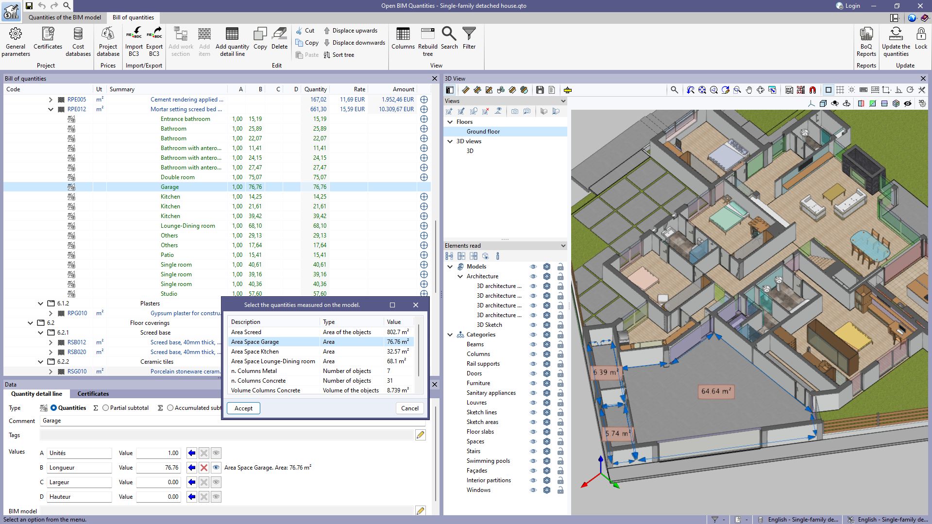
In version 2023.d, the "Quantities on the 2D/3D model" were implemented in the applications that have a "Bill of quantities" tab. This tool has now been enhanced in order to allow users to save quantities measured on the 3D view so that they can be used in several quantity detail lines. To this end, the "Save the current quantities" option has been added to the toolbar of the 3D view. By clicking on it, a window is displayed where a description for the quantity can be entered before saving it. In order to display the list of saved quantities, the "Measurements carried out on the model" option has also been added. This option displays a list of the measurements taken, showing the description, type of measurement (length, area, angle, etc.) and value for each one.

The "Assign the quantities measured on the model to the variable" option, which appears next to each variable in a quantity detail line, has changed the way it works as a result of this new feature. In previous versions, clicking on it assigned the last measurement taken on the 3D view, whereas now the "Measurements carried out on the model" list is displayed to select the saved quantity to be used.

Additionally, next to each variable linked to a quantity on the model, the description, type of measurement (length, area, angle, etc.) and value of the selected measurement can be viewed. Also, the "Delete the link between the variable and the quantities measured on the model" and "View the quantities measured on the model in the 3D view" options have been added. The first option allows users to remove the link between the value of the variable and the quantities measured on the model. The second option allows users to display the representation of the assigned measurement in the 3D view. If this option is used on another variable or if another element is selected in the "Bill of quantities" window, this representation will no longer be displayed.