Introduction
CYPE Connect Classic is a program designed for designing, checking and generating the detailing and detailed check reports of welded and bolted connections with rolled and reinforced double-T sections, welded connections of hollow tubular sections, and welded anchor plates of steel columns.
It can run as a stand-alone program or it can be integrated within CYPE 3D, CYPE's program for 3D structures discretised using bars and sheets.
Work environment
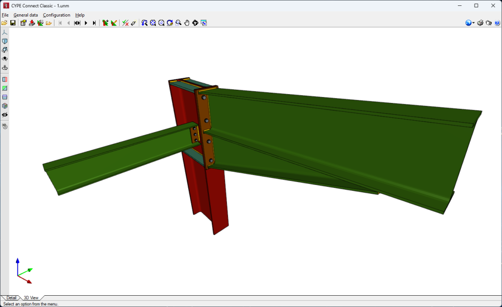
The CYPE Connect Classic work environment is divided into two distinct tabs on the bottom left-hand side of the program: "Detail" y "3D View".
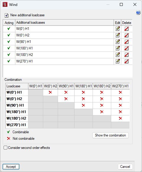
The main toolbar contains different features that allow users to define the general data and configuration of the project. Combinations, loadcases, design options, geometry and connection editing applied to the node, and checking and design are some of these features.
The "Detail" tab shows the details of the selected connection, such as sections, haunch details and plate details, among others.
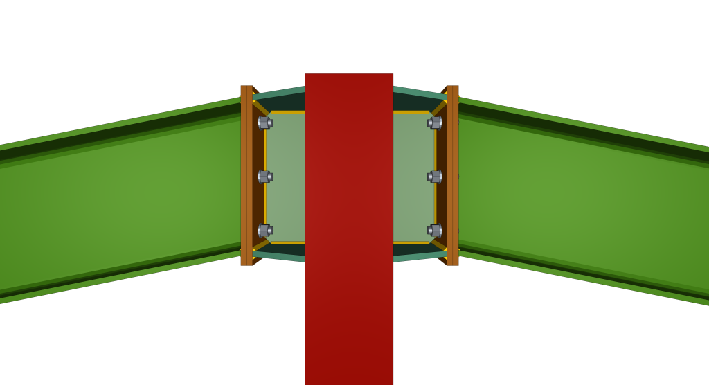
In the "3D View" tab, the 3D model of the connection is displayed together with details of sections, haunches, plates, stiffeners, bolts or welds.
Defining the project characteristics
General data
In the "General data" menu, the options and tools are divided into four groups.
The first group contains the options for selecting and creating combinations and loadcases, the options for their general design, as well as those for managing the section library. The second group shows the options for navigating between the different connections in the project. The third group contains the options for editing the geometry of the node and editing the connection applied to the node. Finally, the "Check" and "Design" options are shown for the edited connection or all the connections in the project.

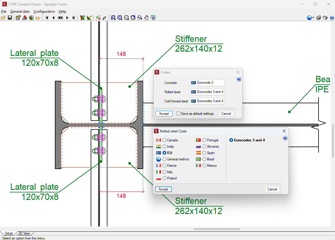
Configuration
The "Configuration" menu contains options for modifying the design standard for the connections, the system of units to be used, the size and orientation of the sheet, the selection of the printer and the styles for the program's reports. The program offers options for sending jobs. The addresses of contacts can be added here so that they are available when a job is sent. With the "Drawings" option, users can create drawing formats and configure the peripherals on which these formats are to be used. In the "Details" section, a library can be created by incorporating CAD files in DXF or DWG formats so that they can be incorporated into the drawings. Finally, the program offers an option to change the background of the program's working area.
Codes available in the program
Creating and editing nodes
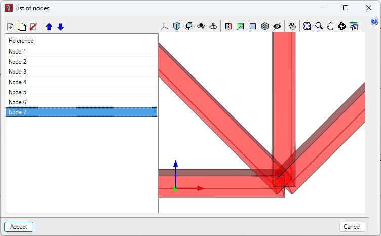
From the "List of nodes" option, available under "General data", users can access the interface to visualise and manage the different nodes in the project.
Click on the "Add" button to add a new node. To make it easier to enter the node, the program allows users to generate the node with the help of predefined types, or to define them themselves.

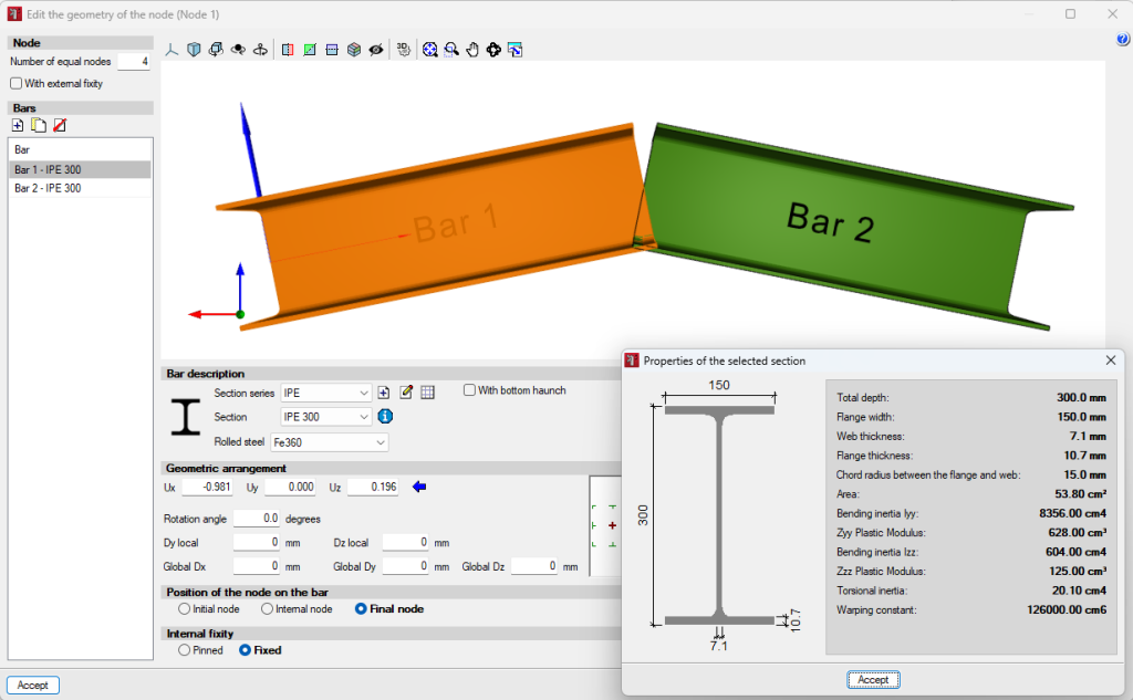
From the "Edit the geometry of the node" option, available under "General data", users can access the interface to define the series and sections of the bars, as well as the loads to be considered in the bar design.
For the description of bars, users can access a manufacturer's library from which they can import section series. Sections can also be created manually and edited.
From the editor, the geometrical layout is also described, as well as the position of the node in the bar and the internal fixity.
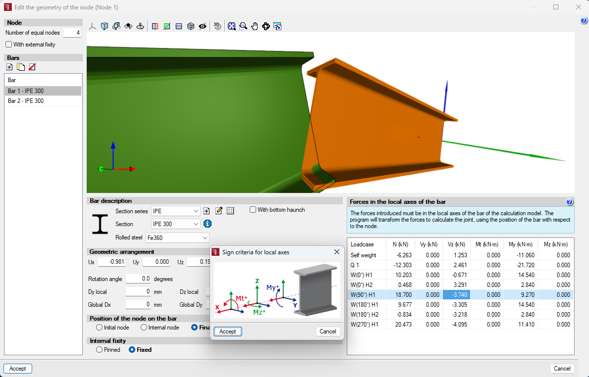
From the node geometry editor, the loads are entered for each of the previously defined loadcases. To do this, the bar is selected and the corresponding loads are entered.
Designing, checking and editing the connection applied to the node
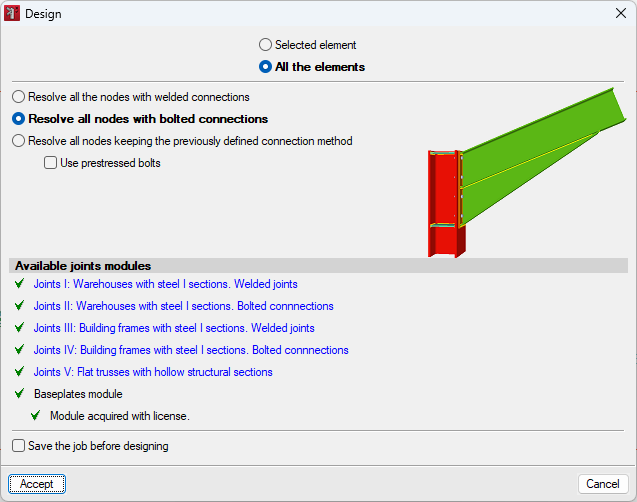
The "Design" option in the "General data" menu allows users to design a selected element or all the elements.
The program has three options for solving the nodes:
- Solving all nodes with welded connections.
- Solving all nodes with bolted connections, with the possibility of using prestressed bolts.
- Solving all nodes by maintaining the previously defined connection method.
The available connection modules are as follows:
- Joints I: Warehouses with steel I sections. Welded joints.
- Joints II: Warehouses with steel I sections. Bolted connections.
- Joints III: Building frames with steel I sections. Welded joints.
- Joints IV: Building frames with steel I sections. Bolted connections.
- Joints V: Flat trusses with hollow structural sections
- Baseplates module.
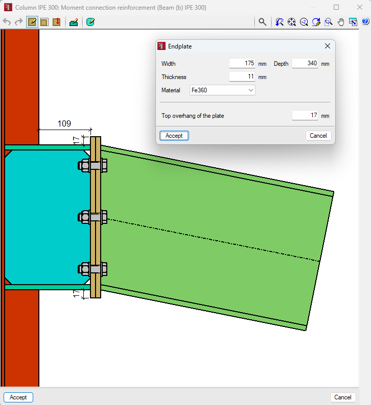
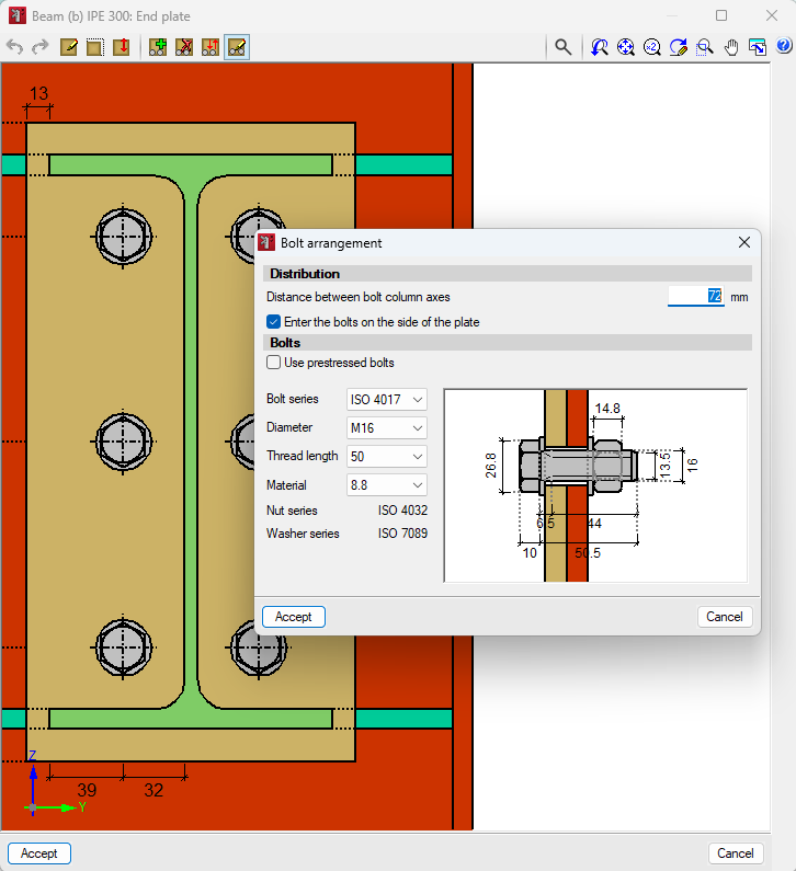
From the "General data" menu, users can access the option to "Edit the joint applied to the node".
On the left-hand side of the editing window is the list of components involved in the connection and, for each of them, a button for editing. On the right-hand side of the list of components is a 3D view of all the modifications made to the node. At the bottom of this view is a list of the node's issues, and at the top are the "Design”, “Check”, ”Complete report of the node” and ”Detailing” options.

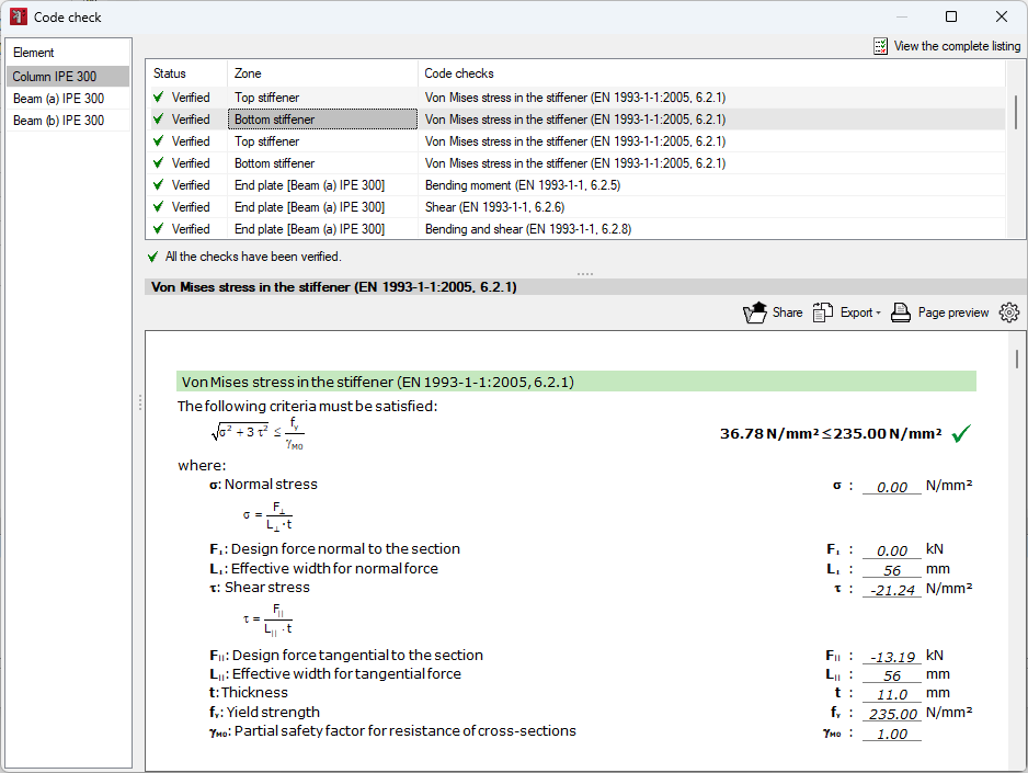
Once the editing has been completed, the code check can be carried out, showing whether or not they are compliant and the area where they are located.
By clicking on each of the lines, the detailed report of each check is displayed in the viewer at the bottom, including a reference to the code, as well as the development of the analysis.
This way, users can check if there is an element in the connection that does not meet one or more of the checks. In this case, the link can be modified and rechecked.
At the top right-hand side, users will find the option to "View the complete listing" of the connection.
A complete report of the connection is available, including the detailed drawings of the connection, the description of the connection components and the summary tables of the checks.
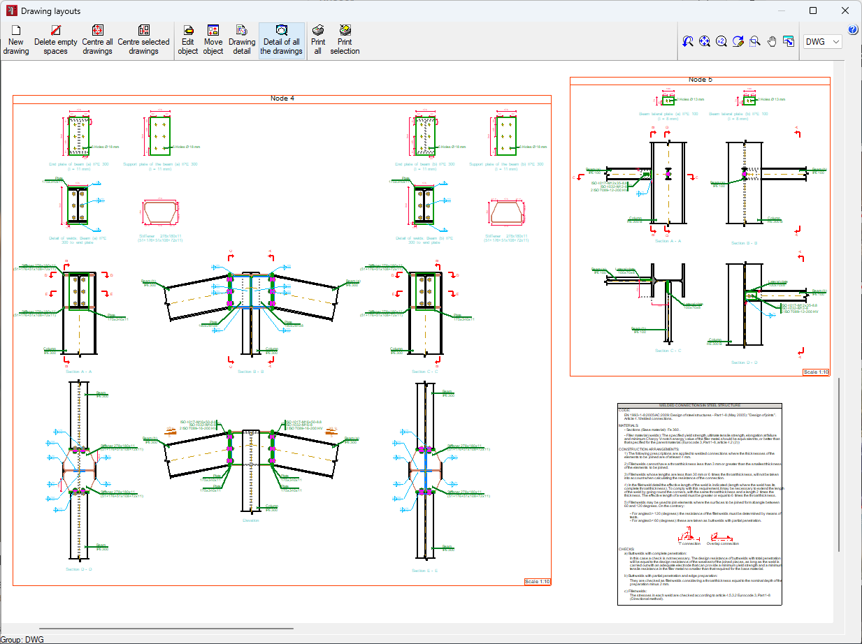
The "Detailing" option allows users to obtain a detailed view of the connection detailing.
The detailing of all the connections is then obtained via the printout of drawings. Here, users can “Print the current view” to obtain the information directly in different formats.
Results
CYPE Connect Classic provides reports and drawings of the connections as results.
- Reports
They provide information on job data, such as the codes considered and the limit states. The reports also provide information on nodes and connections, such as specifications for welded and bolted connections, references and symbols, checks on baseplates, calculations and quantities. - Drawings
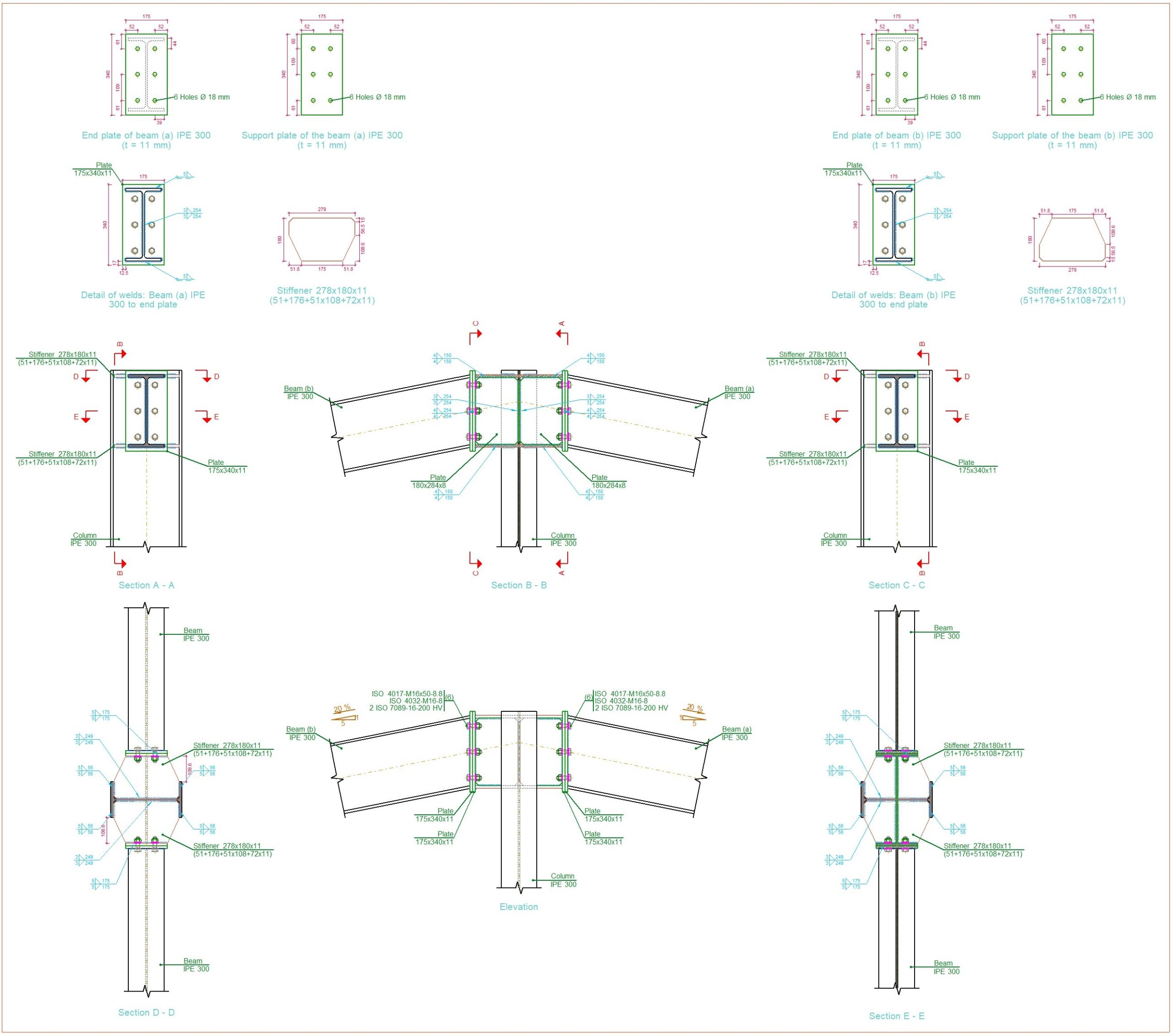
The generated drawings include all connection details.