Update history​​

CYPEPLUMBING

During the introduction and editing process of the installation, the program emits warning messages if there are connections that have not been introduced correctly. It also provides error messages when errors occur that prevent the analysis process of the installation from being carried out correctly and any errors that may arise during the analysis.

These notifications have also been implemented in CYPEPLUMBING Sanitary Systems.

The 2018.h version of CYPEPLUMBING Water Systems allows users to graphically analyse the results of the installation. Users can select the parameters that intervene in the hydraulic design of the installation that they wish to analyse, and the program draws the installation using a colour scale, for a quick and easy view of the results in the 2D and 3D views it provides on-screen (including the new 3D view that has been implemented in this version).

It is possible to study specific result ranges in the global aspect of the installation.

This tool has also been implemented in CYPEPLUMBING Sanitary Systems.

The 2018.h version of CYPEPLUMBING Sanitary Systems includes the 3D View button. This tool shows, in a separate window, the 3D view of the BIM project. This 3D view is the same that appears in the bottom left hand corner of the screen, but the configuration of the visible elements and their perspective are independent in both views.

The new 3D view has also been implemented in CYPEPLUMBING Water Systems.

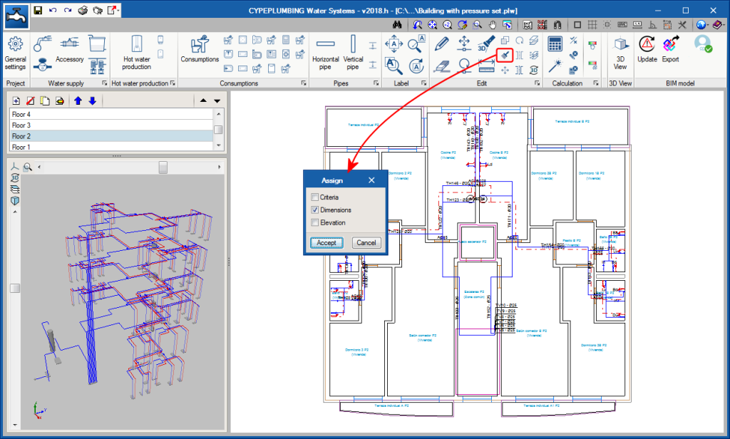
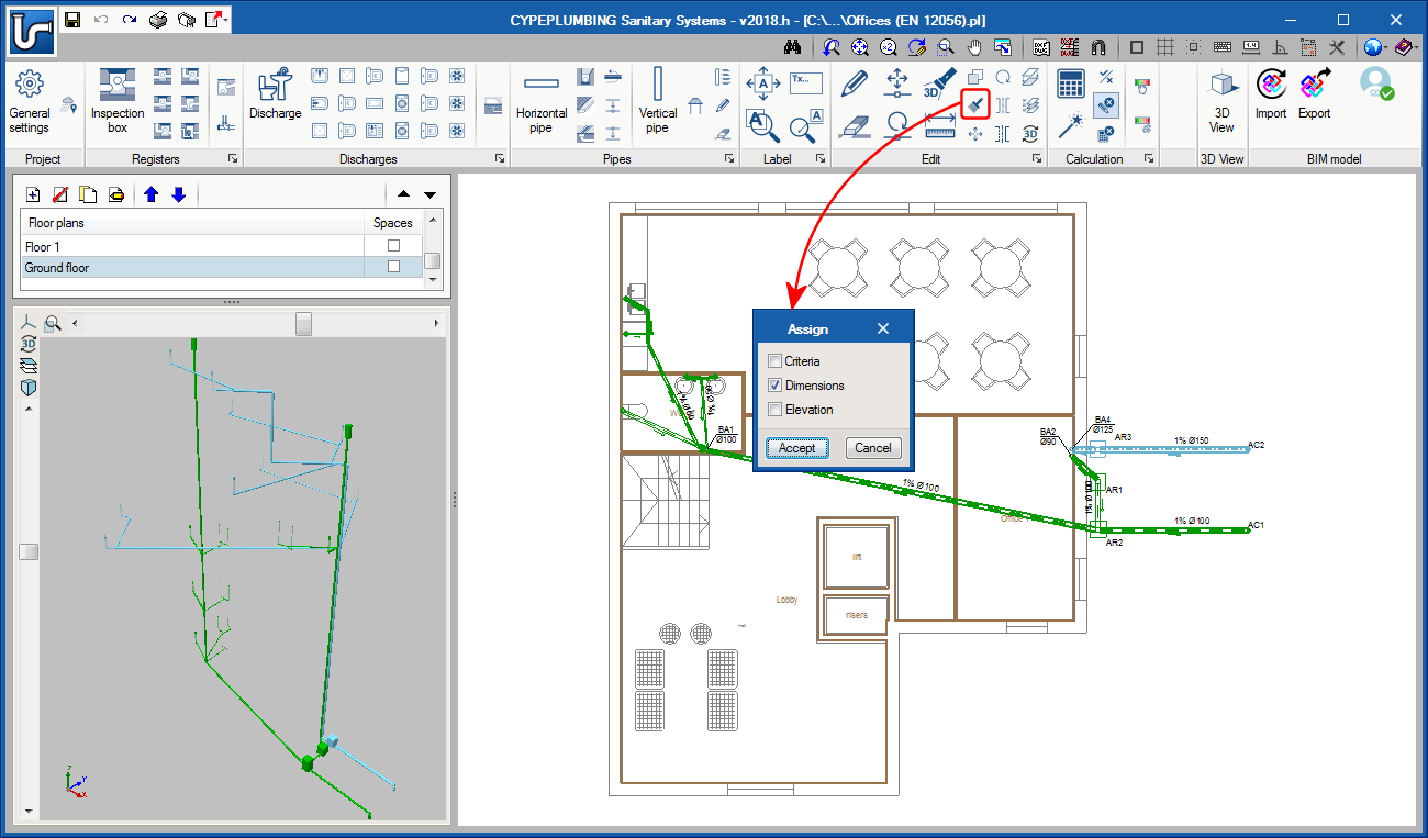
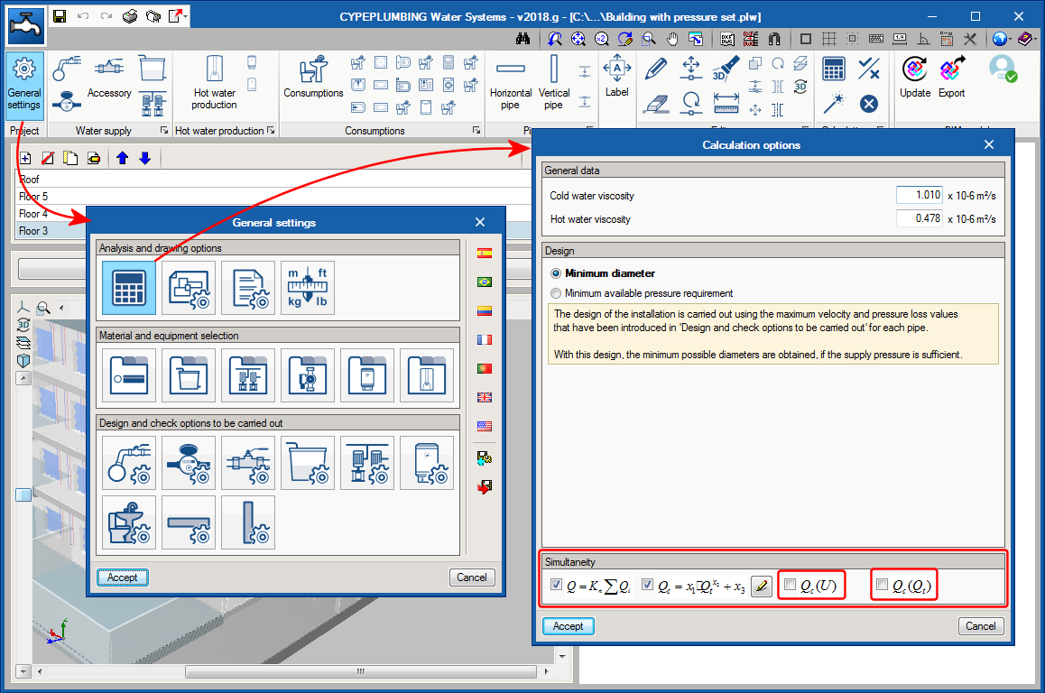
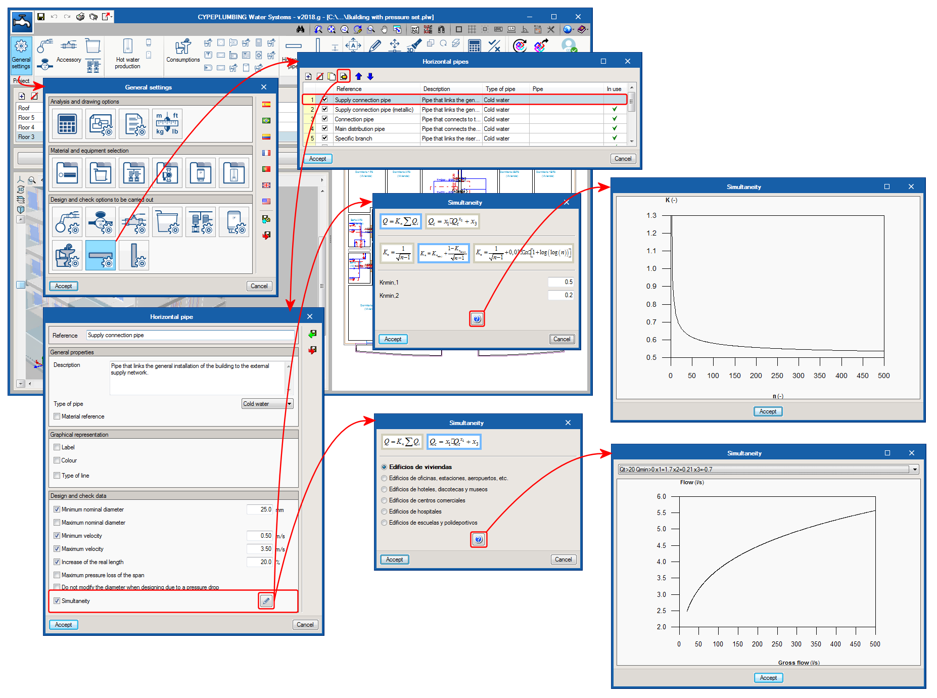
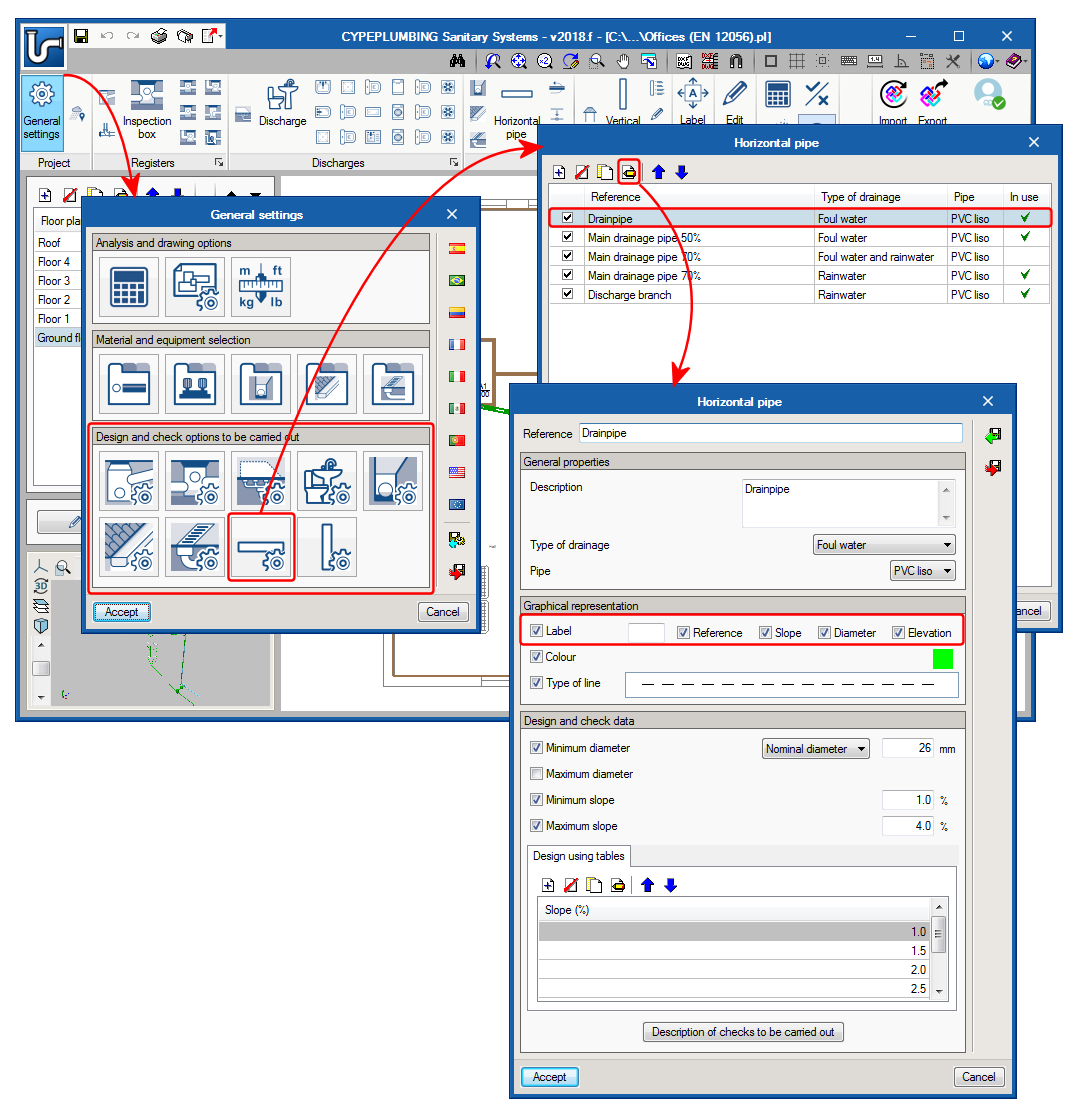
The tool that assigns the properties of the installation has been improved. In previous versions, it was only possible to assign dimensions. As of the 2018.h version, design criteria and dimensions can be assigned to selected elements.

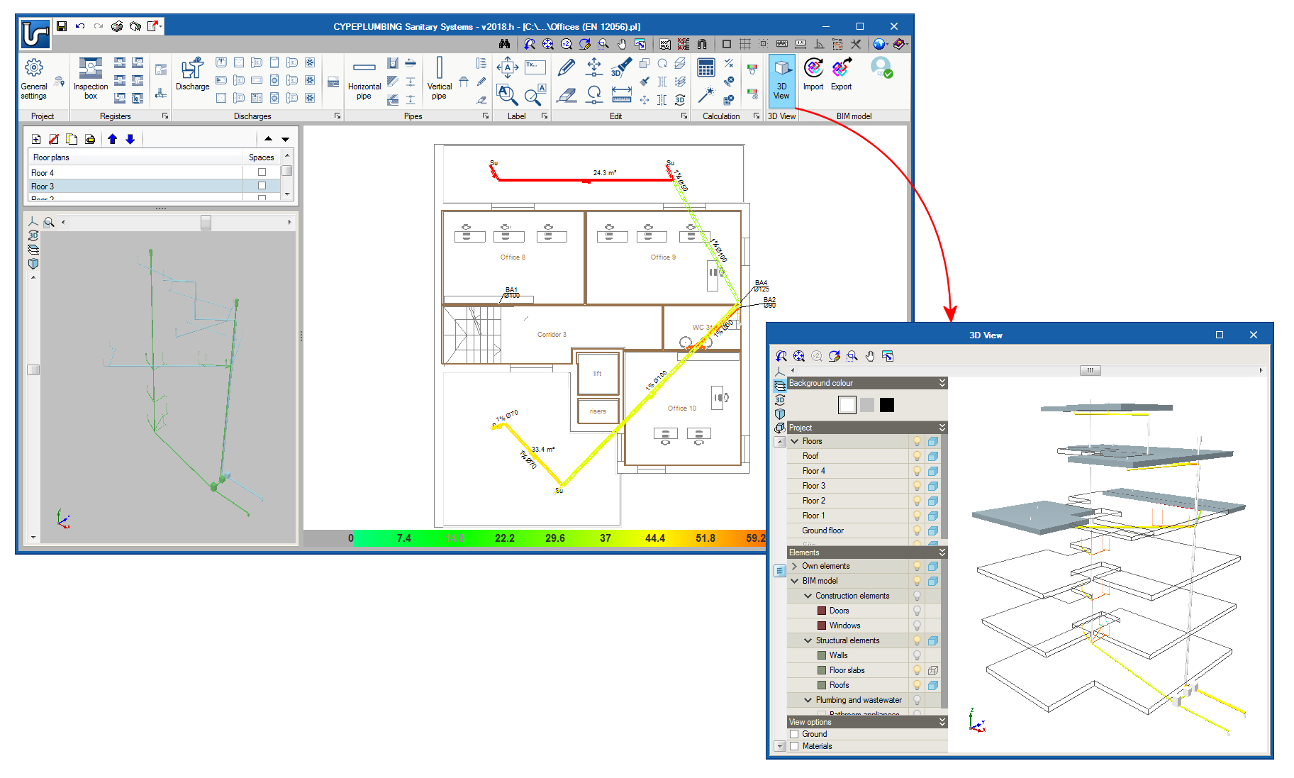
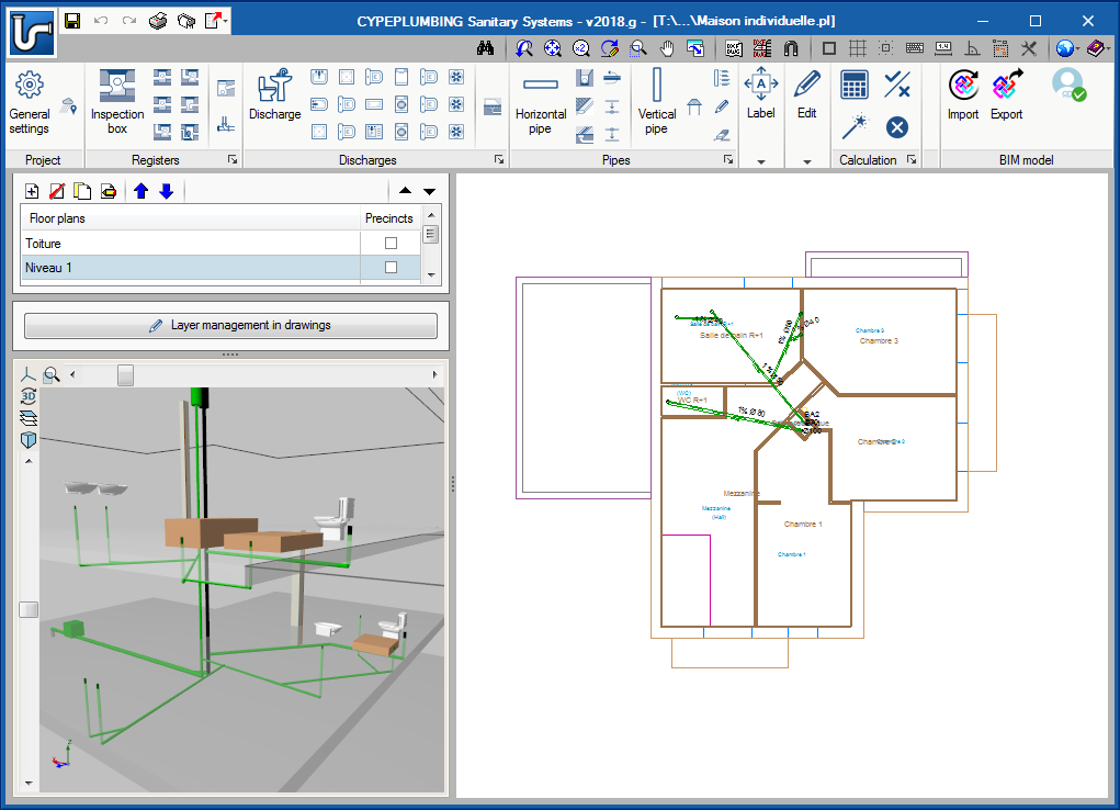
These improvements have also been included in CYPEPLUMBING Water Systems.

During the introduction and editing process of the installation, the program emits warning messages if there are connections that have not been introduced correctly. It also provides error messages when errors occur that prevent the analysis process of the installation from being carried out correctly and any errors that may arise during the analysis.

These notifications have also been implemented in CYPEPLUMBING Water Systems.

The 2018.h version of CYPEPLUMBING Sanitary Systems allows users to graphically analyse the results of the installation. Users can select the parameters that intervene in the hydraulic design of the installation that they wish to analyse, and the program draws the installation using a colour scale, for a quick and easy view of the results in the 2D and 3D views it provides on-screen (including the new 3D view that has been implemented in this version). It is possible to study specific result ranges in the global aspect of the installation.

This tool has also been implemented in CYPEPLUMBING Water Systems.

The dialogue box “Report configuration” has been added and can be accessed from the “General settings” panel.

The 2018.g version of CYPEPLUMBING Water Systems includes new simultaneity calculation methods. Additionally, as an aid to users, the graphs of the simultaneity calculation methods can be represented on screen.

In the previous version of CYPEPLUMBING Water Systems, the program did not represent vertical spans reaching consumption points in the 3D view nor did it export them to IFC format (although they were taken into account in the analysis and design). As of this version (2018.g), these vertical spans are represented in the 3D view and are exported to the IFC that is generated by the program.

In the previous version of CYPEPLUMBING Sanitary Systems, the program did not represent vertical spans parting from drainage equipment in the 3D view nor did it export them to IFC format (although they were taken into account in the analysis and design). As of this version (2018.g), these vertical spans are represented in the 3D view and are exported to the IFC that is generated by the program.

Each installation element that is present in the “Design and check options to be carried out” section of the “General Settings” panel can be of different types. As of the 2018.f version, users can define a specific label for each of these types that contains the reference defined by users and some of the parameters of the element. For example, for horizontal pipes, the label may include the reference, slope, diameter and elevation.

In “Design and check options to be carried out” for each element of the installation (General settings button), the dialogue box that opens upon selecting one of them includes a column which allows users to activate or deactivate any of the catalogue components, so they may be selected during the data introduction process of each element (large button of each section of the top toolbar) or using the small buttons that are available in each section of the toolbar).

The images show how this selection is carried out for discharge elements and the appearance of the dialogue boxes and tool buttons as a result of their selection.