Introduction
CYPEHVAC is a program for designing HVAC systems covering heating, ventilation and air conditioning. This tool is used to design radiators, fan coils, boilers, heat pumps, ducted ventilation networks, heat recovery units, fans and air handling units.
The application can be used to import the necessary information extracted from other Open BIM tools so that both the architectural models and the results of the thermal load analysis can be used in the system design.
Workflows supported by the program
As CYPEHVAC is an Open BIM tool and is connected to the BIMserver.center platform, it offers different workflow options.
Data entry
Free modelling/with templates
- Designing the system using free entry in CYPEHVAC.
- System design in CYPEHVAC based on DXF-DWG, DWF templates or images (.jpeg, .jpg, .bmp, .wmf).
Importing BIM models
If the CYPEHVAC job is linked to a BIM project from the BIMserver.center platform, the following tasks can be carried out:
- Importing the model with the geometry of a building. This generates the floor plan of the building, import the layout of the spaces (the thermal loads can be estimated directly or associated with the thermal load values calculated in stand-alone programs) and allows users to enter the system elements based on the building geometry. The following options are available:
- Importing models designed in CYPE Architecture.
- Importing models designed in IFC Builder.
- Importing models in IFC format (generated by CAD/BIM programs such as Allplan, ArchiCAD and others) uploaded to the BIMserver.center project via the web platform.
- Importing models designed in Autodesk Revit with the Open BIM - Revit Plugin.
- If the architectural model is generated by IFC Builder or CYPE Architecture, users can also import the DXF or DWG templates contained in that model, or the one generated by the program itself (from the building elements entered) when a model is exported to the BIM project.
- Importing the results of programs that can analyse thermal loads so that they can be used in the system design. The available options include the following:
- Importing thermal loads from CYPETHERM LOADS.
- Importing thermal loads from CYPECAD MEP.
- Importing manifolds from programs that can model and design the radiant floor system. Among the options available are the following, which include BIM programs from radiant floor manufacturers:
- Importing manifolds from CYPEHVAC Radiant Floor.
- Importing manifolds from Open BIM GIACOMINI.
- Importing manifolds from Open BIM ORKLI Radiant Floor.
- Importing manifolds from Open BIM POLYTHERM.
- Importing manifolds from Open BIM ROTH.
- Importing manifolds from Open BIM SAUNIER DUVAL.
Data output
- Exporting reports to HTML, DOCX, PDF, RTF and TXT formats.
- Exporting drawings to DXF, DWG and PDF formats.
- Exporting the bill of quantities to FIEBDC-3 format.
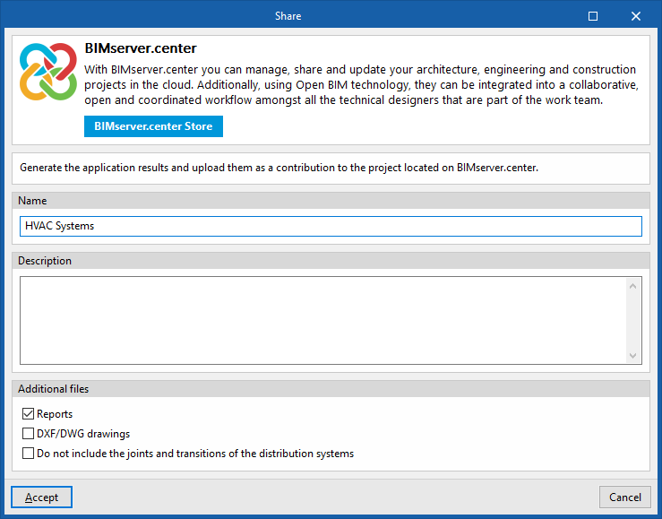
- Exporting the information generated with CYPEHVAC to the BIMserver.center platform using IFC and glTF formats. This allows it to be viewed by authorised project participants. The information generated by CYPEHVAC can be used by the following programs:
- CYPELEC Distribution
This program imports the electrical machines from the HVAC installation and automatically assigns and generates the corresponding receivers in their position. - Autodesk Revit (via the Open BIM - Revit plugin)
Imports the information generated by CYPEHVAC for viewing and management in Revit. Optionally, native Revit elements can be generated from the HVAC systems’ IFC file.
- CYPELEC Distribution

| Note: |
|---|
| If a geometric model is not available or is not imported, you can enter and analyse the installation directly in CYPEHVAC, but it will not be possible to automatically assign loads to the equipment based on the geometry. However, you can manually create and assign loads to the devices or, alternatively, analyse based on the nominal power of the equipment or by forcing the required power in each of them. |
Work environment
The CYPEHVAC interface is divided into two tabs with different work environments: "Installation" and "Bill of quantities". These environments are similar to those in other CYPE tools and have a dockable window system that can be customised to adapt the workspace to the project's needs.
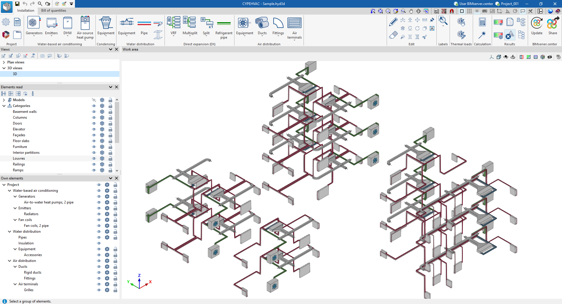
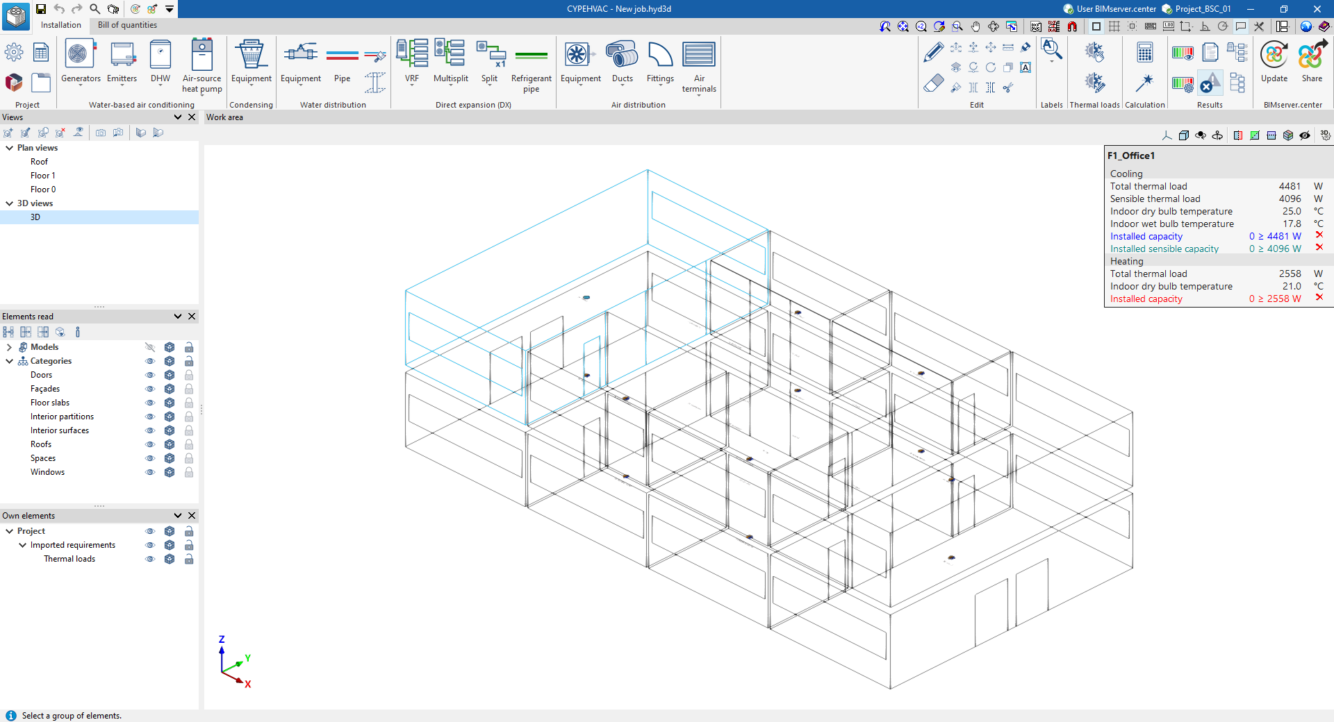
"Installation" tab
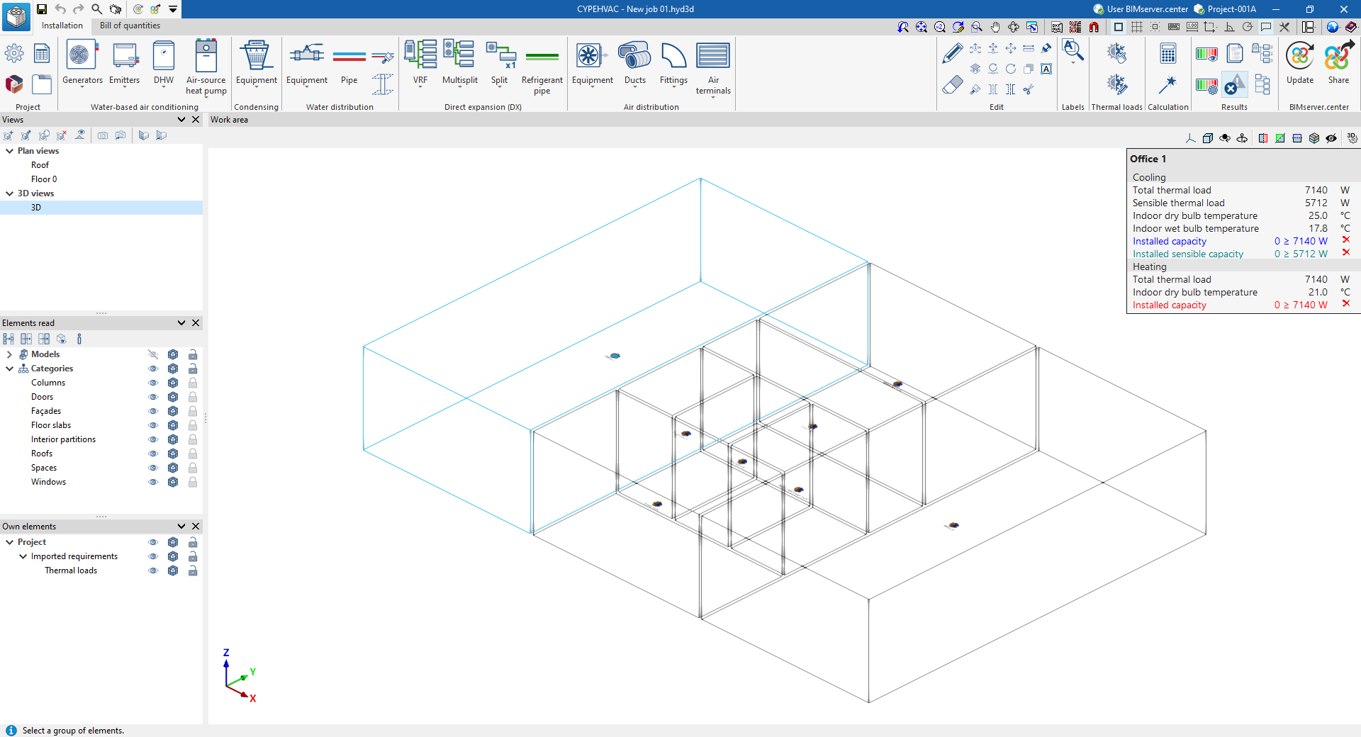
The "Installation" tab has a work environment that allows the system design to be carried out quickly and easily, both in a 3D view and in any type of 2D view (such as floor plans and elevations). This allows the elements in the system to be entered using the most appropriate view at any given time.
This tab displays the following:
- The top toolbar contains the tools for managing the project options; entering and editing the elements of the water-air conditioning systems, water-cooled system, air-source heat pump system and water production air conditioning systems; entering direct expansion systems; entering the elements for the air distribution system; and analysing, checking and designing the system.
- The work area, on the right side of the screen, is where the aforementioned elements are entered, edited and displayed.
- On the left-hand side are several panels with tools for defining the project views and managing the visibility of the elements read and own elements.
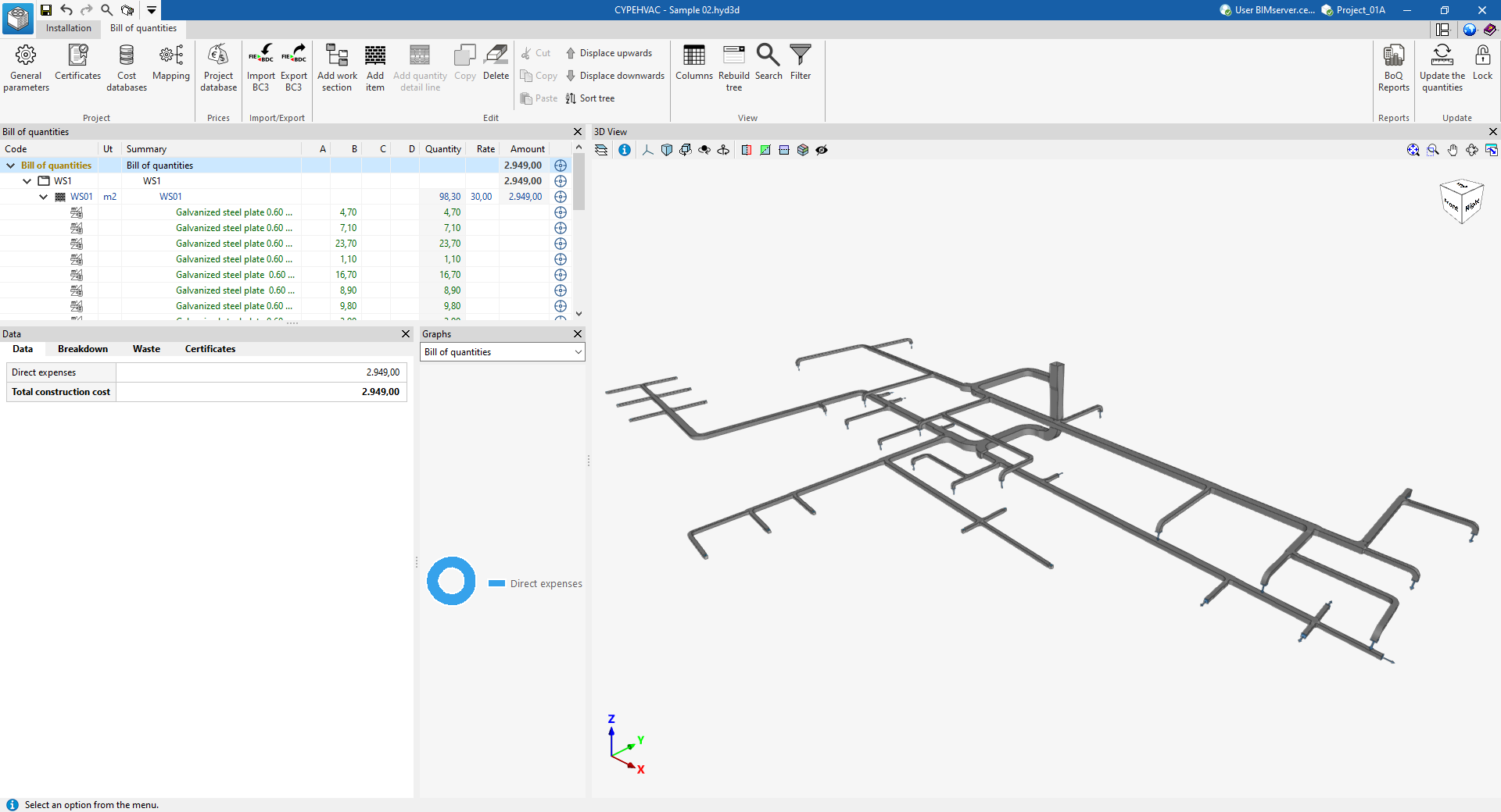
"Bill of quantities" tab
On the other hand, the "Bill of quantities" tab is used to manage the quantities and cost estimations of the installation, and displays the following:
- A top toolbar containing tools for creating and editing bills of quantities, as well as tools for managing and creating reports.
- A graphic window with its own toolbar, located on the right-hand side, where the different elements of the job can be viewed.
- A specific area for structuring the bill of quantities, on the left-hand side.
Sequence of data input and output for the design and analysis of air-conditioning systems
Air-conditioning systems can be defined and analysed in the program using the following input and output sequence:
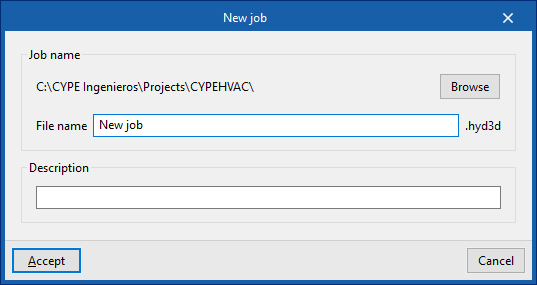
- Creating a new job (from "File", "New").
- (Optional) Linking to BIMserver.center, and importing floor plans and space layouts read from the BIM model, as well as the associated thermal load analysis results and the layout of thermal loads in the space.
- (Optional) If the project does not include the results of the heat load analysis, a heat load estimation is carried out in the process of creating a new job.
- Revising the general parameter settings (from "Project", "General options").
- Defining types of elements. This can be done in two additional ways:
- Loading manufacturers' catalogues (from “Project”, “Catalogue management”).
- Loading or manually entering the generic element libraries (from "Project", "Generic element library").
- Entering, arranging and interconnecting the elements of the system in the work area ("Condensing", "Water-based air conditioning", "DHW", "Air-source heat pump", "Water distribution", "Direct expansion" and "Air distribution" groups) in accordance with the permitted diagrams. Here are some examples:
- Boiler and radiator installation (from "Generators", "Boiler"; from "Emitters", "Radiator"; and from "Water distribution", "Water pipe").
- Heat pump and radiant floor installation (from "Generators", "Air-to-water heat pump, 2 pipes"; from "Emitters", "Radiant floor manifold"; and from "Water distribution", "Water pipes").
- Installation of ducted heat pumps and fan coils (from "Generators", "Air-to-water heat pump, 2-pipes"; from "Emitters", ‘Fan coils, 2-pipe’; from "Water distribution", "Water pipe"; from "Air distribution", "Rigid duct"; and from "Air distribution", "Grille").
- Direct expansion installation, VRF system ("VRF, Outdoor unit, heat pump (2 pipe)", "Indoor unit, wall mounted" and "Refrigerant pipe").
- Assigning thermal loads to devices (‘"Thermal loads" group). This assignment is automatic if both the reference points of the thermal loads and the units covering them are located inside the volumes formed by the spaces read from the geometrical model.
- Analysing the system, displaying the results on the screen and in the results reports ("Analysis" and "Results" groups).
- (Optional) Creating and managing the cost estimations and bills of quantities of the system ("Bill of quantities" tab).
- Obtaining reports and drawings (from "Results", "Reports"; and from "File", "Drawings").
- Exporting to BIMserver.center (from "BIMserver.center", "Share").
Creating a new job, linking to a project and importing data
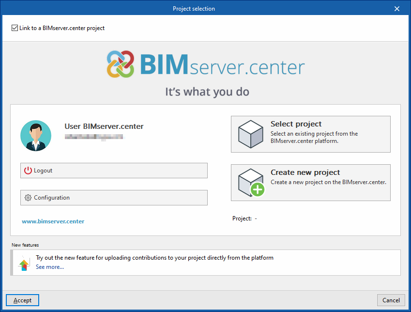
When you launch the application and click on "New", you are given the option to create a "New project". After entering the "File name" and "Description", the project can then be added to an existing project on BIMserver.center.
This is done in the "Project Selection" window, which offers the following options:
- On the left-hand side, you can log in using a BIMserver.center account.
- On the right, use the "Select project" option to choose an existing project. You also have the option to "Create a new project". In that case, the project you create will be visible on BIMserver.center from that point onwards.
- You have the option to start the project without linking it to the BIMserver.center platform. To do this, simply uncheck the box labelled "Link to a BIMserver.center project", which is located in the top-left corner.
Once the new project has been created, you will be taken to the program’s main interface. At any stage of the project, you can share or import project files via the “BIMserver.center” section, located at the top right of the main interface on the “Installation” tab.
Importing BIM models
When creating a new project, if you have selected a project hosted on the BIMserver.center platform via "Select project", the "Import BIM models" window will appear, displaying the files contained in that project in IFC format.
The application allows you to include one or more of the existing models in that project. To do this, tick the "Import" box and confirm.
In addition, in this window, the program offers the following options:
- Geographical location and reference system
Opens a dialogue box to modify the model’s geographical location and reference system.
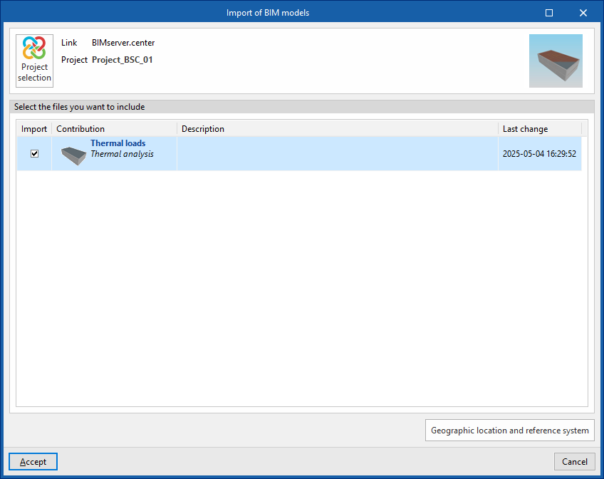
Import results
The program’s various views will then display the imported models.
In addition, the program will have imported the floor plans, the geometry of the spaces and the associated thermal loads, which are displayed as requirements following the import.
In order to import these thermal loads, they must have been included in the BIMserver.center project (for example, after being calculated using CYPETHERM LOADS).
| Note: |
|---|
| "Thermal loads" can be shown or hidden using the controls in the "Imported requirements" section of the "Custom elements" panel, which is located by default at the bottom of the left-hand side. |
Estimation of heat loads
If the BIMserver.center project to which the building has been linked does not include thermal load calculation results, but does contain geometric information for the building’s rooms or spaces, the program offers the option of estimating thermal loads for the imported rooms.

In this case, after accepting the relevant prompt, the following values must be entered in the "Thermal load estimation" window, which allow the thermal load per unit area to be assigned:
- Refrigeration
- Total cooling load
- Sensible cooling load
- Indoor design temperature
- Relative humidity
- Heating
- Heating load
- Indoor design temperature
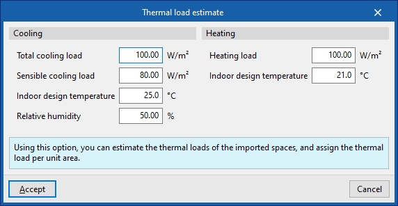
In this case, the program will also have imported the floor plans and the geometry of the rooms from the architectural model data, whilst also generating the thermal loads based on the estimate provided and displaying them as requirements following the import.
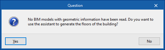
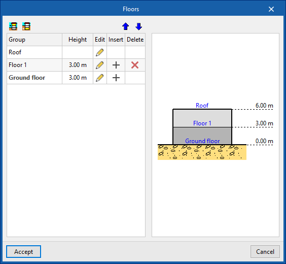
Generating floors
If no BIM model containing geometric data is imported during the process of creating a new project, the software offers the option of using a wizard to generate the building’s floor plans.
In a subsequent step, it will also allow you to import the drawing templates for each floor.
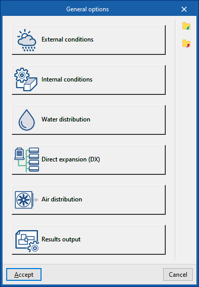
Defining the general project options
In the "Project" group of the main toolbar on the "Installation" tab, you can define the general options of the project:

The available options are as follows:
- External conditions
- Internal conditions
- Water distribution
- Direct expansion
- Air distribution
- Results output
These functions are detailed below.
External conditions
Defines the external air conditions.
- Outdoor air
- Altitude (m)
- Dry-bulb temperature, summer (ºC)
- Wet-bulb temperature, summer (ºC)
- Dry-bulb temperature, winter (ºC)
- Relative humidity, winter (%)
- Wet-bulb temperature, winter (ºC)
- Air properties
- Barometric pressure (mwc)
- Air density (Calculated/User-defined) (kg/m³)
Climate data import
Outdoor condition data can be imported from the ASHRAE Weather Data Viewer 6.0 database using the button to the right of the "Outdoor conditions" window.
To import this data, the following parameters must be defined:
- WMO region
Defines the world region. - Country
Selects the country in the chosen region. - Station name
Selects the meteorological station in the chosen country.
From here, it is also possible to choose the percentile levels of the data to be imported:
- Annual percentile level (Heating)
Selects a level of 99.6% or 99%. - Annual percentile level (Cooling)
- Annual temperatures
Selects a level of 0.4%, 1% or 2% for annual temperatures. - Monthly temperatures
Selects a level of 0.4%, 2% or 5% for monthly temperatures.
- Annual temperatures
Internal conditions
Defines the indoor air conditions.
- Cooling dry-bulb temperature (ºC)
- Relative humidity (%)
- Cooling wet-bulb temperature (ºC)
- Heating dry-bulb temperature (ºC)
Water distribution
This section configures the design criteria for various elements of the water distribution system, such as pipes and expansion vessels, and activates certain checks on them.
Design options
Allows the sizing process of the water distribution system elements to be adjusted:
- Search for the optimal selection
During the design process, the program will search for and select the smallest element in the series that meets all requirements. - Maintain the selection if checks are met
During the design process, the program will attempt to retain the element selected by the user. If the selected element meets the requirements, the program will not change it, even if there is a smaller one that also meets them. However, if the selected element does not comply, the program will replace it with the smallest element that does.
Working fluid
Defines the properties of the working fluid by reference and at different temperatures:
- Reference
- Working fluid properties table
- Temperature (ºC)
- Density (kg/m³)
- Specific heat (J/(kg·ºC))
- Kinematic viscosity (×10⁻⁶ m²/s)
It is possible to import predefined values for water and for water with additives using the assistant to the right:
- Working fluid properties
- Working fluid (Water / Water with ethylene glycol / Water with propylene glycol)
Environmental conditions along the pipe route
- Outdoor temperature (ºC) (Heating / Cooling)
- Indoor temperature (ºC) (Heating / Cooling)
Pipe design criteria
- Maximum velocity (m/s)
- Maximum head loss per section (mwc/m)
- Equivalent length (%)
Expansion vessel design criteria
- Filling pressure (mwc) (Heating / Cooling)
- Relief valve setting pressure (mwc) (Heating / Cooling)
Checks
- Maximum inlet temperature to emitters (ºC) (optional)
- Minimum inlet temperature to emitters (ºC) (optional)
- Maximum heat loss percentage in pipes (%)
- Operating point (tolerance) (ºC)
Direct expansion
Design options
Allows the design process of the direct expansion system elements to be adjusted:
- Search for the optimal selection
During the design process, the program will search for and select the smallest element in the series that meets all requirements. - Maintain the selection if checks are met
During the design process, the program will attempt to retain the element selected by the user. If the selected element meets the requirements, it will not be changed, even if there is a smaller one that also meets them. However, if it does not comply, the program will replace it with a suitable one.
Refrigerant charge limit concentration
This section allows the verification of the refrigerant charge limit.
To "Check the R-410A refrigerant charge limit (EN378)", select the "Building type" from the following:
- Category A: Hospital
- Category B: Residential, commercial, educational, public access
- Category C: Offices and administrative premises
- Category D: Industrial
Selecting a building type displays the associated "Refrigerant concentration limit".
It is also possible to "Check the R32 refrigerant charge limit (IEC60335-2-40)".
Automatic routing
Configures the distances used by the "Automatic routing (VRF)" option in the "Calculation" group.
- Indoor unit
- Flow box
- Outdoor unit
- Relative installation level
- Minimum spacing between rows
Available diameters
Allows you to define which refrigerant line diameters are available by activating or deactivating the corresponding boxes.
Air distribution
This section configures the design criteria for various air distribution system elements, such as ducts, and activates certain checks on them.
Design options
Allows the design process of the air distribution system elements to be adjusted:
- Search for the optimal selection
During the design process, the program will search for and select the smallest element in the series that meets all requirements. - Maintain the selection if checks are met
During the design process, the program will attempt to retain the element selected by the user. If it meets the requirements, it will not be changed. Otherwise, it will be replaced with a compliant one.
Duct design criteria
- Maximum allowable velocity (m/s)
- Maximum allowable pressure drop (Pa/m)
- Permissible duct dimensions
- Dimension (mm)
- Maximum allowable aspect ratio (n:1)
Calculate duct heat loss (optional)
Enables the thermal analysis of heat loss through air ducts when calculating or sizing the installation.
- Maximum percentage of heat losses in ducts (%)
- Minimum insulation thickness for ducts
- Defined for ducts in the following categories:
- Installed indoors (Heating, Cooling)
- Installed outdoors (Heating, Cooling)
- Further down, enter the "Thermal conductivity of reference material".
- Defined for ducts in the following categories:
Calculate airborne noise transmission through duct system
Enables acoustic calculation in air ducts when calculating or designing the installation.
- 63 Hz band (optional)
- Minimum sound power level
- Acoustic map
- Reference / From / To / Colour
Results output
Allows you to configure different options related to the program’s results output:
Show maintenance areas (optional)
Displays maintenance areas near equipment when this information is available.
- Opacity
Element references
Allows automatic generation of element references to be activated or deactivated.
- Generate references when calculating (optional)
- Overwrite previously assigned references (optional)
Specification options
Configures the documentation produced by the program (drawings, lists, measurements, etc.), establishing the criteria for generating descriptions of equipment, materials or services selected from the catalogues downloaded from Open BIM Database and included in the project.
- Commercial specification of the selected product
Descriptions will specify only the selected product. - Specification with equivalent product option
Descriptions will specify the selected product and indicate the possibility of using an equivalent. - Description without specifying a commercial product
Descriptions will not specify a particular commercial product.
Labels
Configures the information labels displayed over elements.
- Legend (optional)
- Type (optional)
- Reference (optional)
- Selection (optional)
- Length (optional)
- Dimensions (optional)
- Level (optional)
- Text size
- Colour
Colour
Modifies the display colour (on screen and in drawings) for elements of the following categories:
- Air distribution
- Outdoor air (ODA)
- Supply air (SUP)
- Extraction air (ETA)
- Exhaust air (EHA)
- Return air (RCA)
- According to the type of installation
- Undefined
- Water distribution
- Heating - Supply
- Cooling - Supply
- Heating - Return
- Cooling - Return
- Cooling and heating - Supply
- Cooling and heating - Return
- Refrigeration lines
- 2 pipes
- 3 pipes
The button on the right restores the "Default values".
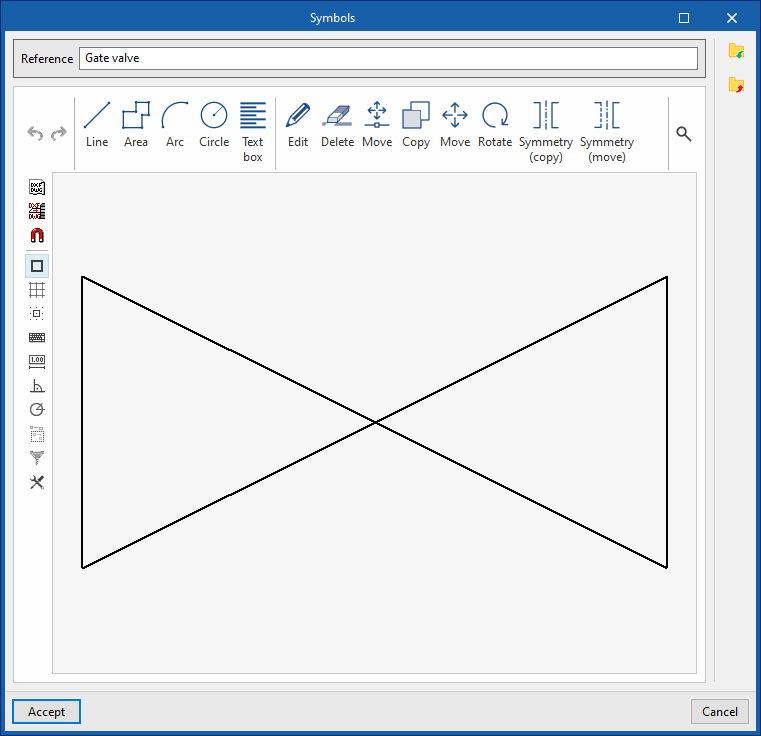
Symbols for drawings
Create symbols for different elements in the drawing using a graphic editor where you can insert lines, areas, arcs, circles and text boxes.
The program also offers the possibility of importing a series of predefined symbols using the wizard in the top toolbar.
Maintenance areas for various units
Tools for managing manufacturers' catalogues
In the "Project" group of the main toolbar of the "Installation" tab, there is an option for managing the manufacturer's product catalogues to incorporate them into the project:

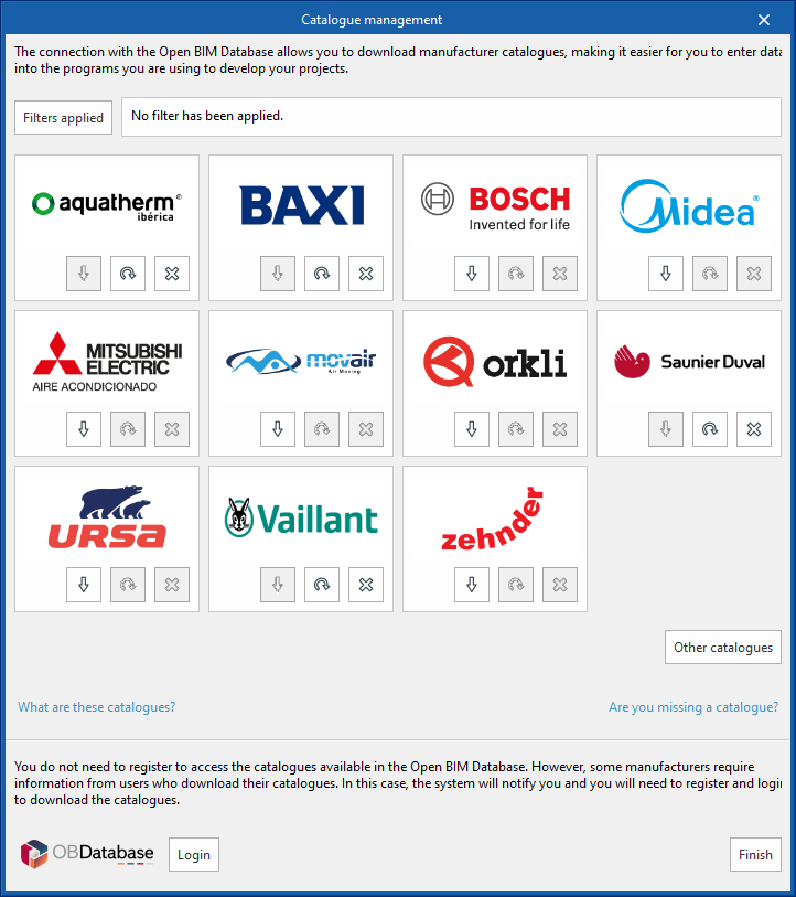
Catalogue management
This allows manufacturers' catalogues to be downloaded using the connection to the Open BIM Database, making it easier to enter data into the program for project development.
Clicking on this option opens a window with the available manufacturer catalogues.
Using the "Filters applied" option, filters can be applied by element "Category", "Language" and "Country" so that only manufacturers offering product catalogues with these characteristics are displayed.
Catalogue download
The following options are shown for each manufacturer:
- Download
Downloads the manufacturer's catalogue. The products in the catalogue will be available in the project. - Update
Updates the selected manufacturer's catalogue to the latest version, deleting the version downloaded in the project. - Delete
Deletes the selected manufacturer's catalogue. The products in the catalogue will no longer be available in the project.
Connection to Open BIM Database
At the bottom of this dialogue box, the program allows users to log in with their Open BIM Database account and password.
| Note: |
|---|
| The products from the downloaded catalogues can be selected when entering the elements in the system. |

Catalogues available from the "Other catalogues" option
Managing the elements added to the project
In the "Project" section of the main toolbar on the "Installation" tab, you will find the option to manage the items added to the project:

Items entered
This allows you to view the details of each of the installation components included in the model, such as their reference number, position, type and specifications, in the following tables:
- Condensing circuit
- Generators
- Cooling towers
- Water-based air conditioning
- Generators (Air-to-water heat pumps, 2-pipe; Air-to-water heat pumps, 4-pipe; Water-to-water heat pumps; Boilers)
- Heating units (Radiators; Towel radiators; Underfloor heating manifolds)
- Fan coils, 2-pipe (Cassette/wall-mounted/floor-mounted/ceiling-mounted/ducted fan coils, 2-pipe)
- Fan coils, 4-pipe (Cassette/wall-mounted/floor-mounted/ceiling-mounted/ducted fan coils, 4-pipe)
- Air handlers (2-pipe air conditioning units; 4-pipe air conditioning units)
- ACS (Heat exchangers; Heat accumulators)
- Domestic heat pump system
- Compact units, monobloc air-source heat pump system
- Outdoor units, split-type heat pump system
- Indoor units with DHW storage tank, split-type heat pump system
- Wall-mounted indoor units, split-type heat pump system
- Outdoor units, hydraulic split-system heat pump
- Indoor units with DHW storage tank, hydraulic split-system heat pump
- Wall-mounted indoor units, hydraulic split-system heat pump
- Water distribution
- Pipes
- Hydraulic separators
- Manifolds
- Accessories
- Storage tanks
- Pumps
- Heat exchangers
- Expansion tanks
- Indoor hydraulic units
- Direct expansion
- VRF (VRF outdoor units, heat pump (2-pipe/3-pipe); indoor units, cassette/wall-mounted/floor-standing/ceiling-mounted/water-cooled/air curtain/ducted/heat recovery; centralised control)
- Multisplit (Multisplit outdoor units; Multisplit indoor units: cassette, wall-mounted, floor-standing, ceiling-mounted, and ducted)
- 1x1 split system (1x1 split outdoor units; 1x1 split indoor units: cassette, wall-mounted, floor-standing, ceiling-mounted, or ducted)
- Flowcharts
- Collectors
- Referrals
- Refrigeration systems
- Air distribution
- Fans
- Heat recovery units
- Starting point for the pre-installation of ductwork
- Rigid ducts
- Semi-flexible ducts
- Flexible ducts
- Joints
- Air terminals (Grilles; Diffusers; Vents; Vent plenums)
- Fittings (Fire dampers; Filters; Flow regulators; Silencers; Plenums; Connection plates; Covers)
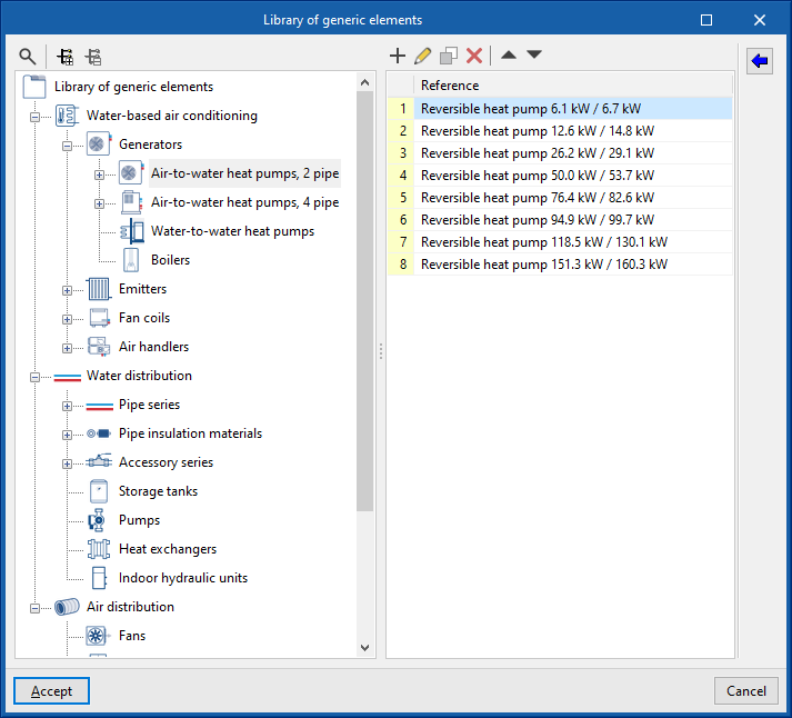
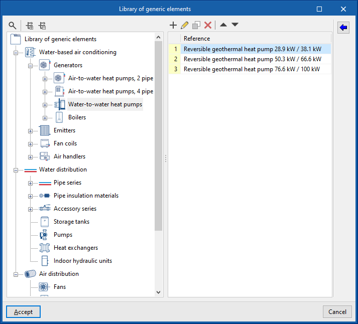
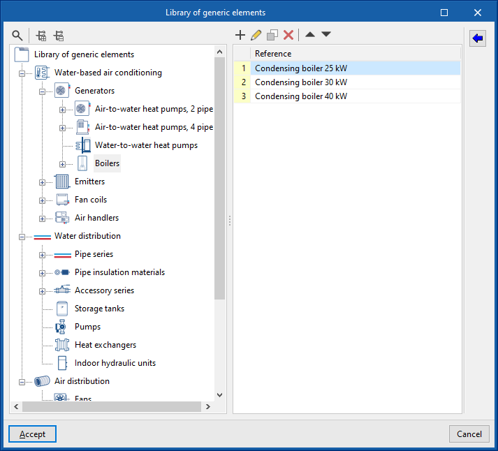
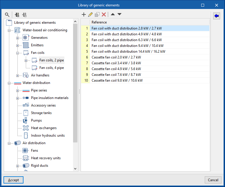
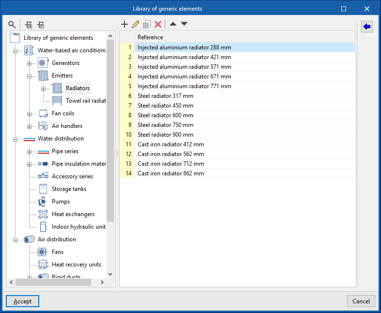
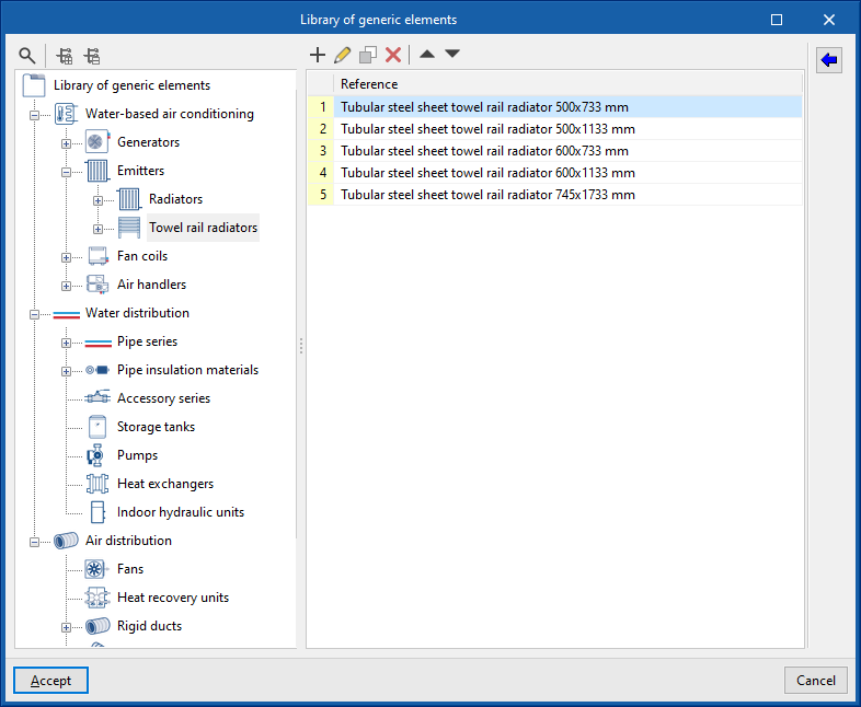
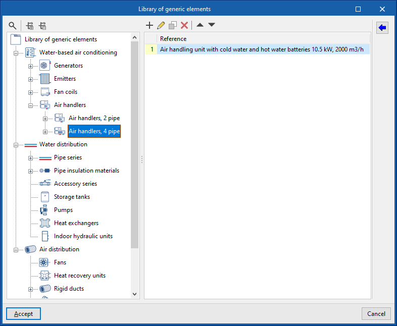
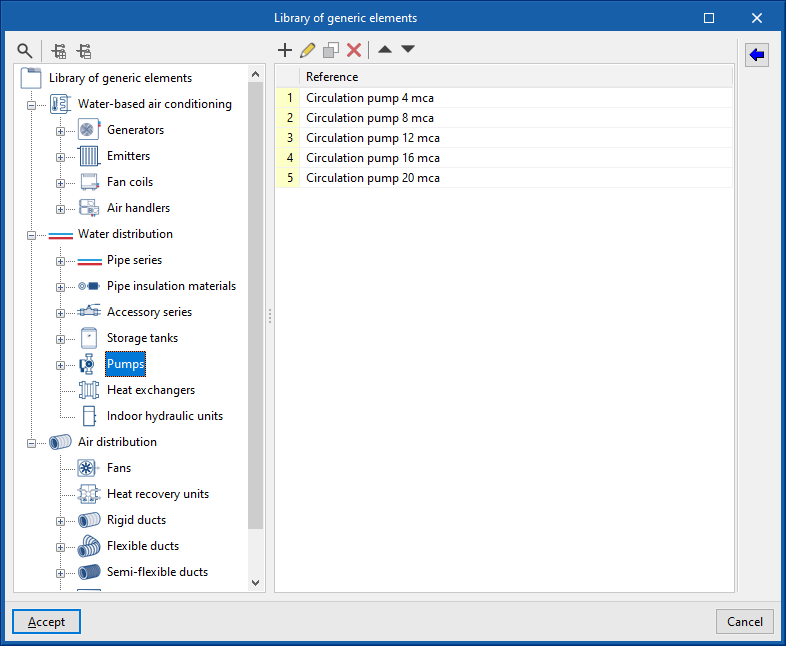
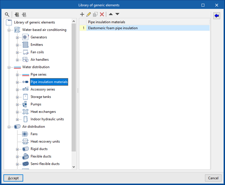
Managing the project's generic elements library
In the "Project" group of the main toolbar on the "Installation" tab, you will find the option to manage the project's generic element library:

Generic elements library
You can create and manage generic type libraries of the following elements:
- Water-based air conditioning
- Generators (air-water heat pumps, 2 pipes, air-water heat pumps, 4 pipes, water-water heat pumps, boilers)
- Emitters (radiators, towel radiators)
- Fan coils (fan coils, 2 pipes, fan coils, 4 pipes)
- Air conditioners (air conditioners, 2 pipes, air conditioners, 4 pipes)
- DHW cylinders
- Water distribution
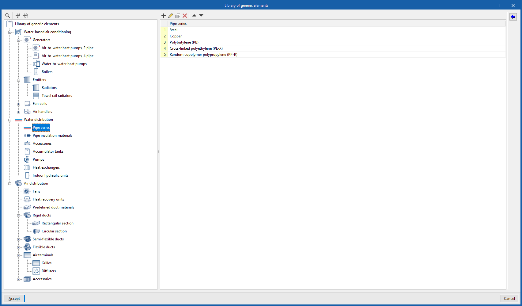
- Pipe series
- Insulation for pipes
- Fittings
- Accumulators
- Pumps
- Exchangers
- Hydraulic indoor units
- Air distribution
- Fans
- Heat recovery units
- Predefined materials for ducts
- Rigid ducts (rectangular section, circular section)
- Semi-flexible ducts (rectangular section, circular section)
- Flexible ducts (rectangular section, circular section)
- Air terminals (grilles, diffusers)
- Fittings (fire dampers, filters, flow regulators, silencers)
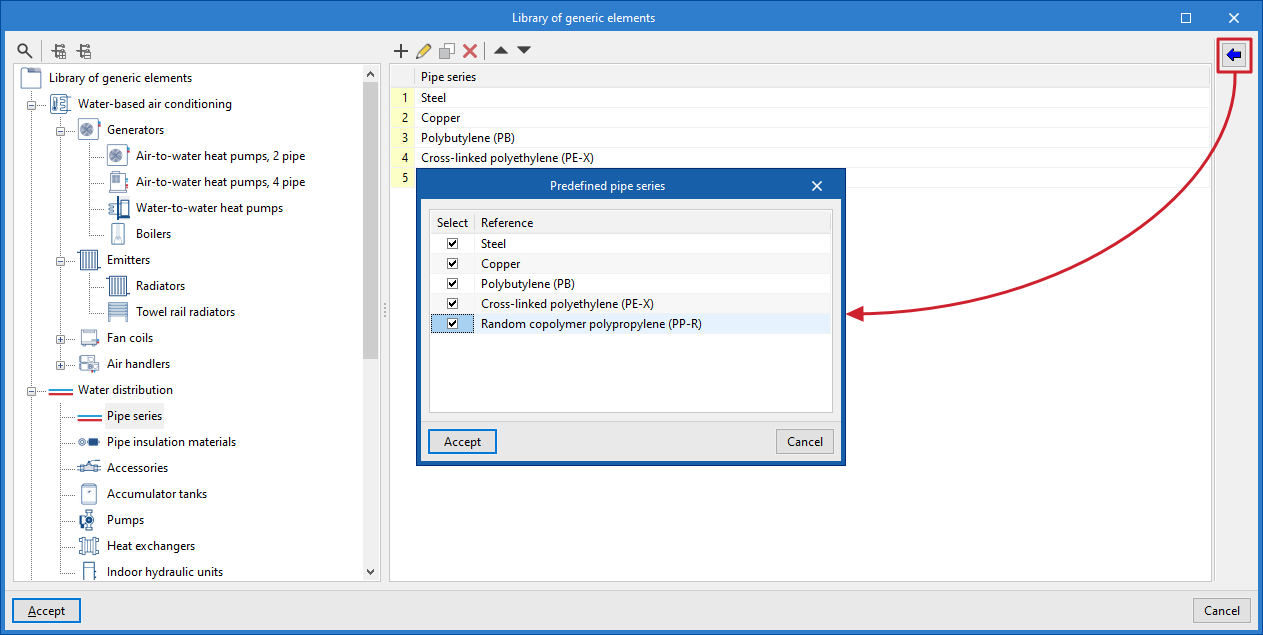
Importing predefined types
Predefined types for different elements can be imported using the wizard available on the right.
Automatic loading of predefined types
When creating a new project, the program automatically loads all the predefined types from the generic libraries for all elements.
| Note: |
|---|
| The generic elements created in this library can be selected when entering the system components using the other options in the program. |
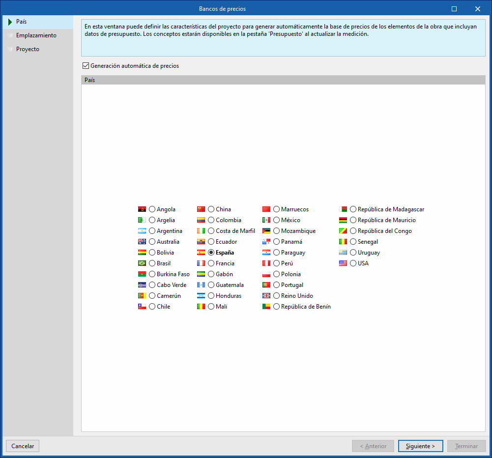
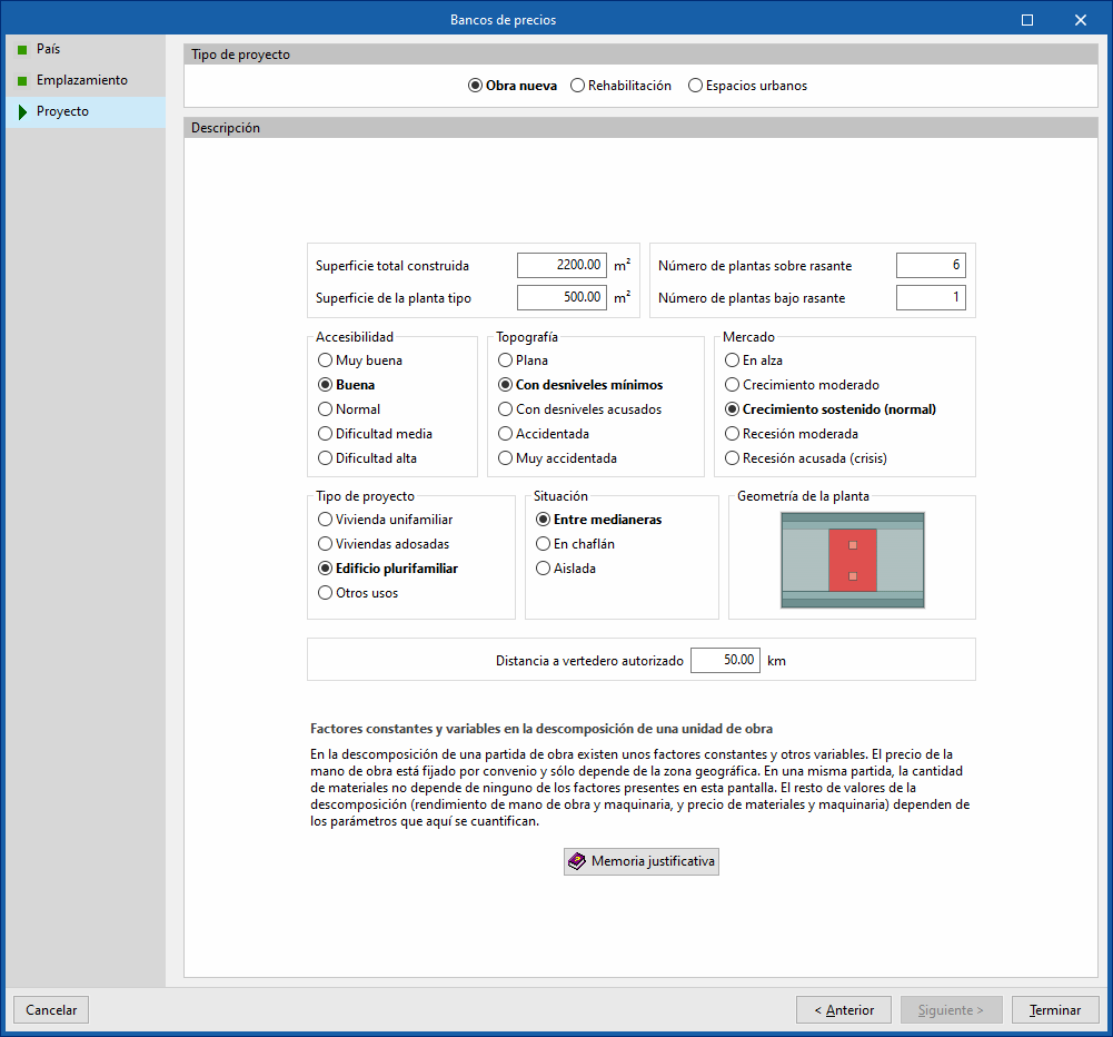
Configuring cost databases
In the "Project" section of the main toolbar on the "Installation" tab, you will find the option to configure the program's cost databases.

Cost databases
The "Cost databases" option allows you to define the project’s characteristics to customise the automatic generation of prices for project elements that include bill of quantities data.
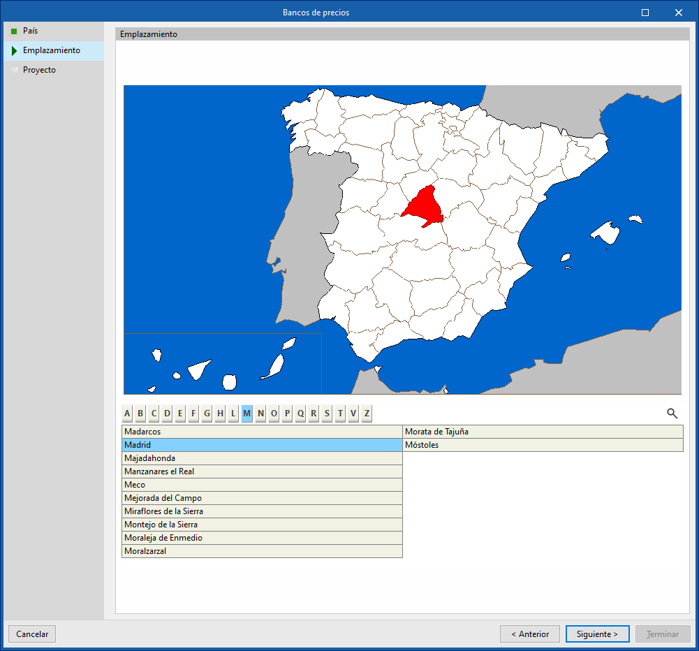
To do this, open a wizard where the following parameters are defined:
- Country
Select a country. To continue, you must tick the "Automatic price generation" box. - Location
Select a location within the specified country. - Project
Specifies the type of project (new build, refurbishment or urban spaces), as well as descriptive parameters such as floor area, accessibility, topography and location of the plot, market conditions, intended use of the project, floor plan layout, and distance to the authorised landfill site. At the bottom, there is a "Justification report " detailing the breakdown of the cost of the construction units and the methodology used to determine and update prices.
The selection made applies adjustments to the breakdown of the work items generated by the program, such as the cost of labour and ancillary materials. It also converts the prices into the currency of the selected country.
| Note: |
|---|
| Users can select products from the Open BIM Database’s manufacturer catalogues that include pricing data and place them in the model via the “Installation” tab. The program will then automatically generate the unit prices for these elements when you switch to the “Bill of quantities” tab and use the “Update quantities” option. |
Inserting generators (water-based air conditioning)
Under the "Installation" tab, in the "Generators" menu within the "Water-based air conditioning" section of the main toolbar, you can define and enter the following items:

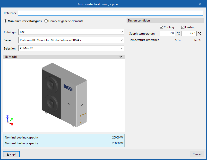
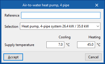
Air-to-water heat pump
Allows air-to-water heat pumps to be installed in a two-pipe or four-pipe system:
- Air-to-water heat pump, 2-pipe system
- Air-to-water heat pump, 4-pipe system
When installing an air-to-water heat pump, the following parameters must be specified:
- Reference
- Manufacturer catalogues / Generic element
library
The program allows you to select and import data from "Manufacturer catalogues" or the "Generic element library", provided these have been configured beforehand in the relevant options within the "Project" section. - Design condition
- Flow temperature (Cooling / Heating) (optional on air-to-water heat pumps, 2-pipe systems)

Library of generic air-to-water heat pumps
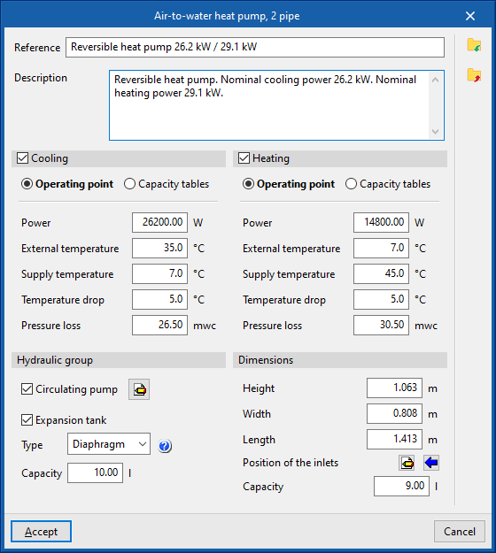
In the "Generic element library" option, within the "Project" section, you can create and edit the libraries of available generic air-to-water heat pump types.
The specifications for each type of air-to-water heat pump are as follows:
- Reference
- Description
- Cooling (optional)
- Operating point (Power; Outdoor temperature; Supply air temperature; Temperature difference; Pressure drop)
- Capacity tables (Power; Temperature drop; Pressure drop)
- Heating (optional)
- Operating point (Power; Outdoor temperature; Supply air temperature; Temperature difference; Pressure drop)
- Capacity tables (Power; Temperature drop; Pressure drop)
- Hydraulic group
- Circulation pump (optional)
- Midpoint (Flow; Pressure)
- By parameters (Flow rate; Pressure)
- Expansion tank (optional)
- Type (Open / Closed / Diaphragm)
- Capacity
- Circulation pump (optional)
- Dimensions (Height; Width; Length; Position of sockets; Capacity)
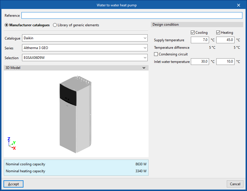
Water-to-water heat pump
Allows for the installation of water-to-water heat pumps.
When installing a water-to-water heat pump, the following parameters must be specified:
- Reference
- Manufacturer catalogues / Generic element
library
The program allows you to select and import data from "Manufacturer catalogues" or the "Generic element library", provided these have been configured beforehand in the relevant options within the "Project" section. - Design condition
- Supply air temperature (Cooling (optional) / Heating (optional))
- Condensing circuit (optional)
- Inlet water temperature (Cooling (optional) / Heating (optional))
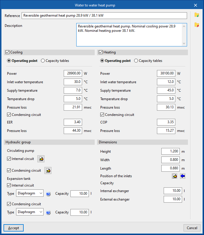
Library of generic water-to-water heat pumps
In the "Generic element library" option, within the "Project" section, you can create and edit the libraries of available generic water-to-water heat pump types.
The specifications for each type of water-to-water heat pump are as follows:
- Reference
- Description
- Cooling (optional)
- Operating point (Power; Outdoor temperature; Supply air temperature; Temperature difference; Pressure drop; Condensing circuit (optional))
- capacity tables
- Internal circuit (Power; Temperature drop; Pressure drop)
- Condensing circuit (optional) (EER; Pressure drop)
- Heating (optional)
- Operating point (Power; Outdoor temperature; Supply air temperature; Temperature difference; Pressure drop; Condensing circuit (optional))
- Capacity tables
- Internal circuit (Power; Temperature drop; Pressure drop)
- Condensing circuit (COP; pressure drop)
- Hydraulic group
- Circulating pump (optional)
- Inner circuit
- Midpoint (Flow; Pressure)
- By parameters (Flow rate; Pressure)
- Condensing circuit
- Midpoint (Flow; Pressure)
- By parameters (Flow rate; Pressure)
- Inner circuit
- Expansion tank (optional)
- Internal circuit
- Type (Open / Closed / Diaphragm)
- Capacity
- Condensing circuit
- Type (Open / Closed / Diaphragm)
- Capacity
- Internal circuit
- Circulating pump (optional)
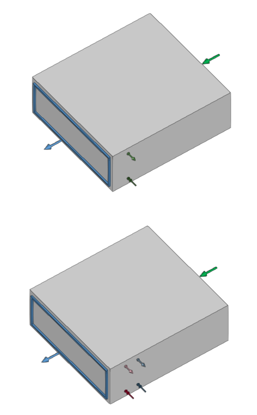
- Dimensions (Height; Width; Length; Position of the inlets; Capacity; Internal exchanger; External exchanger)
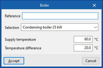
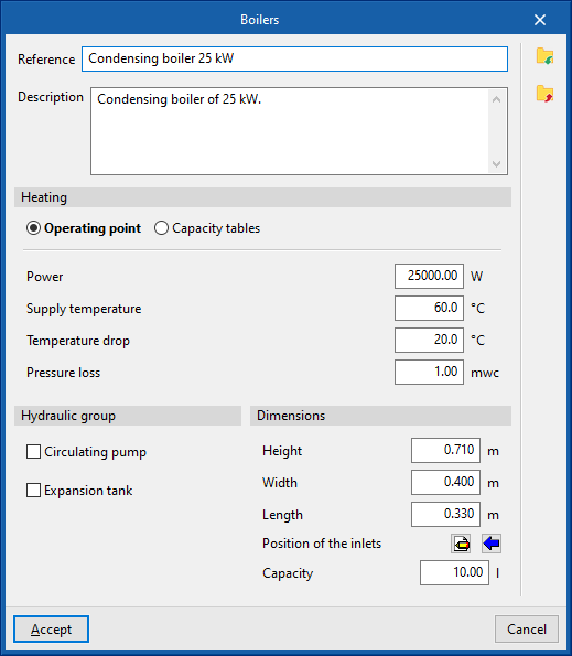
Boiler
Allows you to add boilers.
When entering a boiler, the following parameters must be specified:
- Reference
- Selection
The program allows you to select and import data from the "Generic elements library", provided this has been configured beforehand in the relevant options within the "Project" section. - Supply temperature
- Temperature difference
Generic boiler library
In the "Generic element library" option, within the "Project" section, you can create and edit the libraries of available generic boiler types.
The data associated with each type of boiler are as follows:
- Reference
- Description
- Heating
- Operating point (Power; Supply temperature; Temperature drop; Pressure drop)
- Capacity tables (Power; Pressure drop)
- Hydraulic group
- Circulation pump (optional)
- Midpoint (Flow; Pressure)
- By parameters (Flow rate; Pressure)
- Expansion tank (optional)
- Type (Open / Closed / Diaphragm)
- Capacity
- Circulation pump (optional)
- Dimensions (Height; Width; Length; Position of sockets; Capacity)
Entering emitters (water-based air conditioning)
Within the "Installation" tab, the following elements can be defined and entered in the "Emitters" menu of the "Water-based climate control" group in the main toolbar:

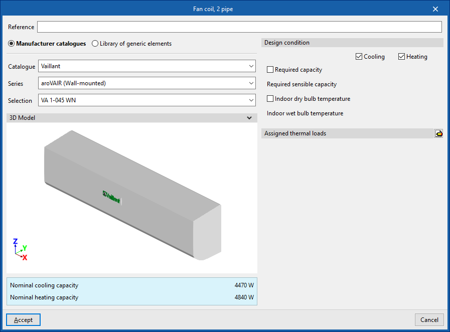
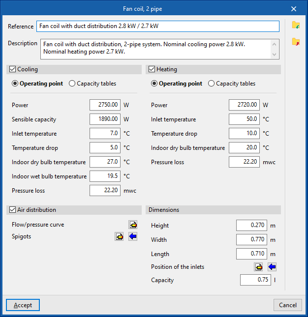
Fan coil
Inserts fan coils (with direct discharge or ducted distribution) for a two-pipe or four-pipe system:
- Fan coil, 2 pipe
- Fan coil, 4 pipe
When inserting a fancoil, the following parameters must be specified:
- Reference
- Catalogue / Selection
The program selects and imports data from "Manufacturer catalogues", if available, or from the "Library of generic elements" using the wizard available on the right. - Design conditions
- Required capacity (optional) (Heating (optional) / Cooling (optional))
- Required sensible capacity (Cooling (optional))
- Indoor dry bulb temperature (Heating (optional) / Cooling (optional))
- Indoor wet bulb temperature (Cooling (optional))
- Assigned thermal loads
Defines the following percentages on the values of the thermal loads for heating and/or cooling of the project. The program automatically assigns loads according to the arrangement of the terminal elements in the model.- % Assigned heating capacity
- % Assigned total cooling capacity
- % Assigned sensible cooling capacity
- % Required heating load
- % Required total cooling load
- % Required sensible cooling load
Library of generic fan coils
Within the "Project" group, in the "Library of generic elements" option, the libraries of available 2-pipe and 4-pipe generic fan coil types can be created and edited.
The data associated with each type of 2-pipe or 4-pipe fan coil is as follows:
- Reference
- Description
- Refrigeration (optional)
- Operating point (Power; Sensible capacity; Inlet temperature; Temperature drop; Indoor dry bulb temperature; Indoor wet bulb temperature; Pressure loss)
- Capacity tables (Power; Sensible capacity; Pressure loss)
- Heating (optional)
- Operating point (Power; Inlet temperature; Temperature drop; Indoor dry bulb temperature; Pressure ^loss)
- Capacity tables (Power; Pressure loss)
- Air distribution (optional)
- If this option is checked, the program considers the fancoil to be a ducted distribution fancoil.
- Flow/pressure curve
- Midpoint (Flow rate; Pressure)
- Point (Flow rate; Pressure)
- Outlets
- Inlets
- Installation
- Air flow type (Outside air (ODA) / Supply air (SUP))
- Inlet can be disconnected (optional)
- Geometry
- Type (Rectangular / Circular)
- Width x Height / Diameter
- Installation
- Inlets
- Flow/pressure curve
- Dimensions (Height; Width; Length; Position of inlets; Capacity)
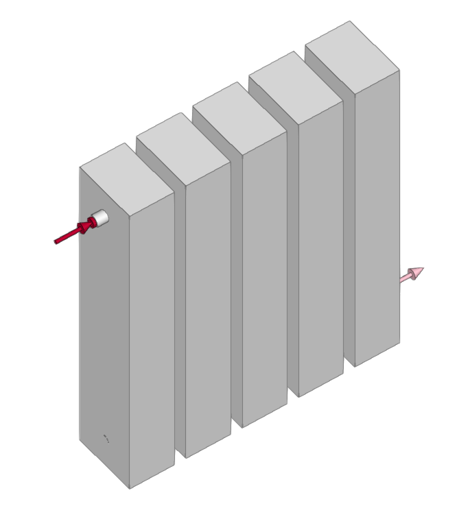
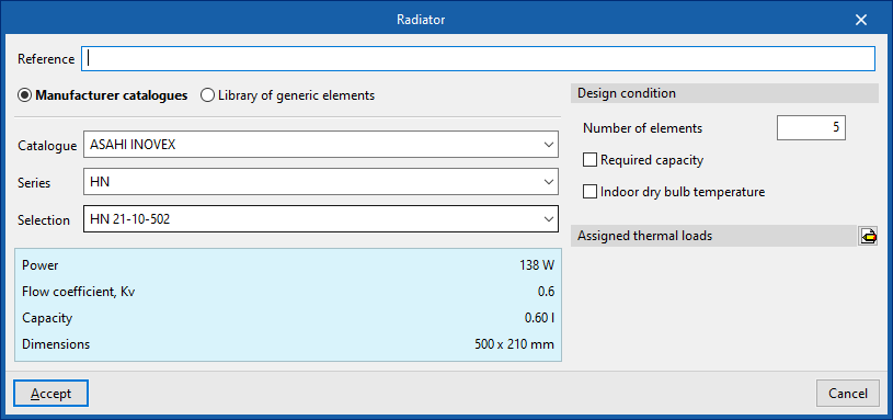
Radiator
Enters radiators.
When entering a radiator, the following parameters must be specified:
- Reference
- Selection
- The program can select and import data from the "Library of generic elements" using the wizard on the right-hand side.
- Number of elements
- Design conditions
- Required capacity (optional)
- Indoor dry bulb temperature
- Assigned thermal loads
- Defines the following percentages on the values of the heating thermal loads of the project. The program automatically locates loads according to the arrangement of the terminal elements in the model.
- % Assigned heating capacity
- % Required cooling load
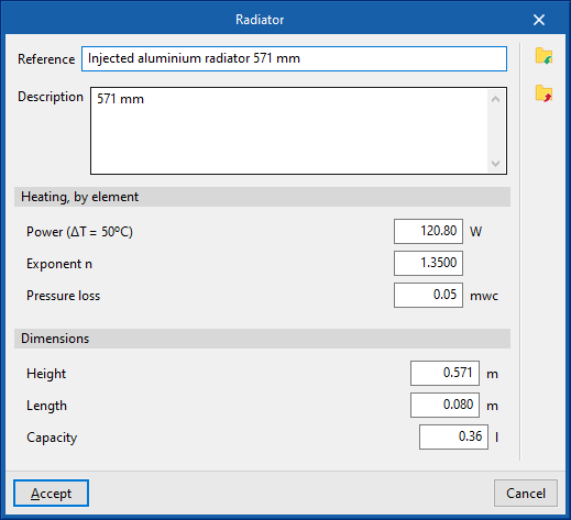
Library of generic radiators
Within the "Library of generic elements" option, in the "Project" group, the available libraries of generic radiator types can be created and edited.
The data associated with each type of radiator is as follows:
- Reference
- Description
- Heating, by element
- Power (ΔT=50ºC)
- Exponent n
- Pressure loss
- Dimensions (Height; Length; Capacity)
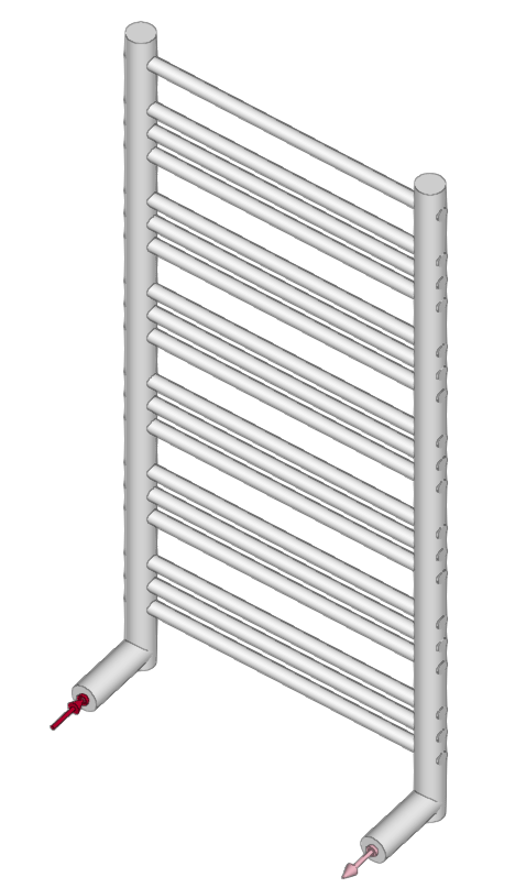
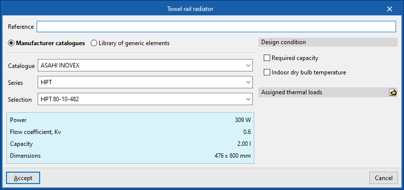
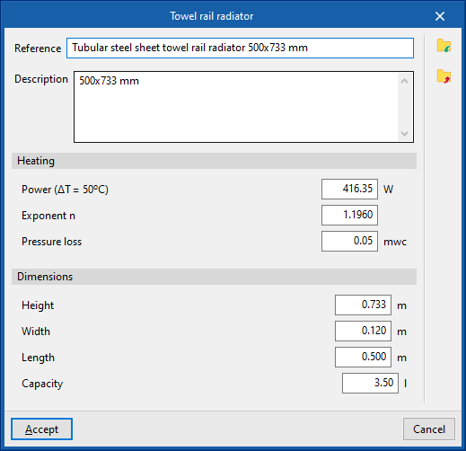
Towel rail radiator
Enters towel rail radiators.
To enter a towel rail radiator, the following parameters must be specified:
- Reference
- Selection
- The program can select and import data from the "Library of generic elements" using the wizard on the right-hand side.
- Number of elements
- Design conditions
- Required capacity (optional)
- Indoor dry bulb temperature
- Assigned thermal loads
- Defines the following percentages on the values of the heating thermal loads of the project. The program automatically locates loads according to the arrangement of the terminal elements in the model.
- % Assigned heating capacity
- % Required cooling load
Library of generic towel rail radiators
Within the "Library of generic elements" option, in the "Project" group, the available libraries of generic towel rail radiator types can be created and edited.
The data associated with each type of towel rail radiator is as follows:
- Reference
- Description
- Heating, by element
- Power (ΔT=50ºC)
- Exponent n
- Pressure loss
- Dimensions (Height; Length; Capacity)
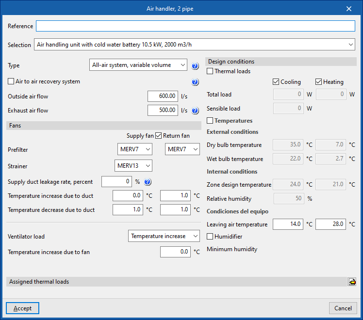
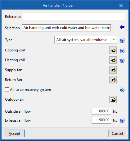
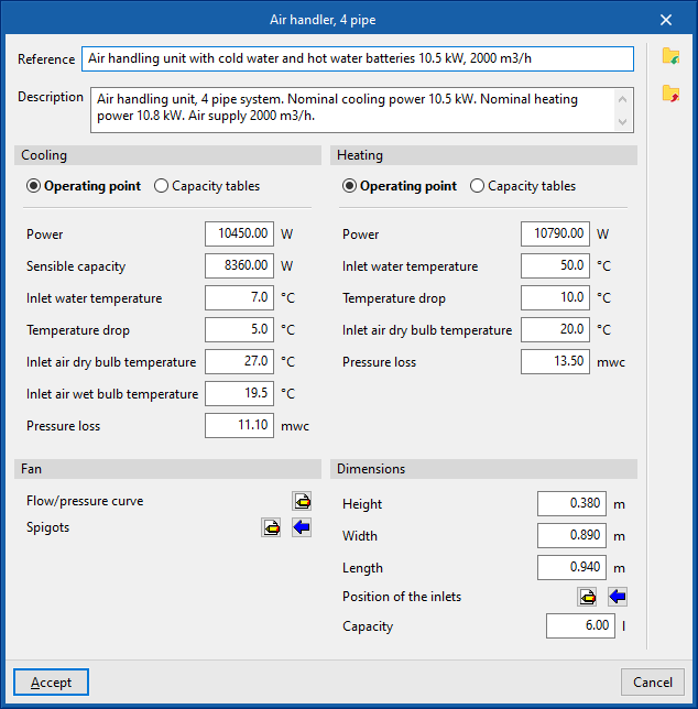
Air handler
Enters air conditioners for a two-pipe or four-pipe system:
- Air handler, 2 pipe
- Air handler, 4 pipe
When entering an air handler, the following parameters must be specified:
- Reference
- Selection
- The program selects and imports data from the "Library of generic elements" using the wizard available on the right hand side.
- Description
- Type (All air system, constant volume / All air system, variable volume)
- Cooling coil (optional in "Air handling unit, 2-pipe")
- Heating coil (optional for "Air handling unit, 2-pipe")
- Supply fan
- Return fan
- Air to air recovery system (optional)
- Type (Sensible / enthalpy)
- Efficiency (%)
- Outdoor air
- Pre-filter
- Design parameters
- Outside air flow
- Exhaust air flow
Library of generic air handlers
In the "Library of generic elements" option, within the "Project" group, the libraries of available generic 2-pipe and 4-pipe air conditioning unit types can be created and edited.
The data associated with each type of 2-pipe or 4-pipe air conditioner are as follows:
- Reference
- Description
- Cooling (optional for "Air handler, 2 pipe")
- Operating point (Power; Sensible power; Inlet water temperature; Temperature drop; Inlet air dry bulb temperature; Inlet air wet bulb temperature; Pressure loss)
- Capacity tables (Power; Sensible capacity; Pressure loss)
- Heating (optional on "Air conditioner, 2 pipes")
- Operating point (Power; Inlet water temperature; Temperature drop; Inlet air dry bulb temperature; Pressure loss)
- Capacity tables (Power; Power output; Pressure drop)
- Fan
- Flow/pressure curve
- Midpoint (Flow; Pressure)
- Point (Flow; Pressure)
- Outlets
- Inlets
- Installation
- Type of air flow (Outside air (ODA) / Supply air (SUP) / Extract air (ETA) / Exhaust air (EHA))
- Inlet can be disconnected (optional)
- Geometry
- Type (Rectangular / Circular)
- Width x Height / Diameter
- Flow/pressure curve
- Dimensions (Height; Width; Length; Position of inlets; Capacity)
The program will display warnings for the connections in the system that has not been completed, without hindering the analysis of the other system.
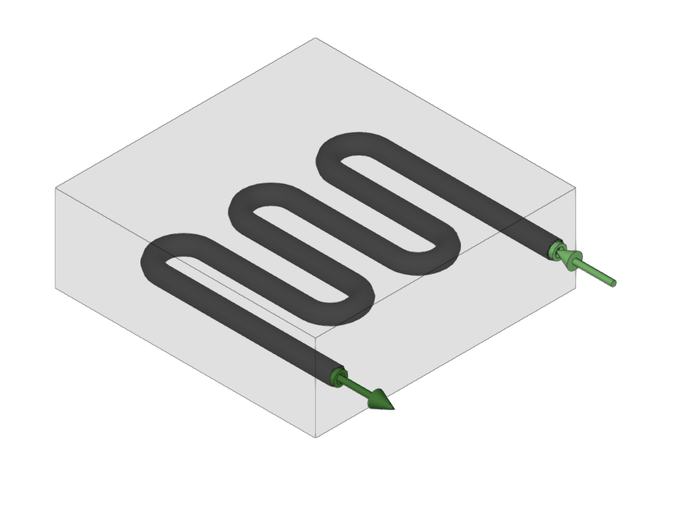
Radiant floor manifold
Enters radiant floor manifolds.
When entering a radiant floor manifold, the following parameters must be specified:
- Reference
- Design conditions
- Power (Cooling (optional) / Heating)
- Minimum inlet temperature (Heating)
- Maximum inlet temperature (Cooling (optional))
- Pressure loss (Cooling (optional) / Heating)
- Volume of water supplied (Heating)
- Thermal loads assigned
- Defines the percentages assigned to the equipment on the values of the thermal loads of the project. The program automatically assigns loads according to the arrangement of the terminal elements in the model.
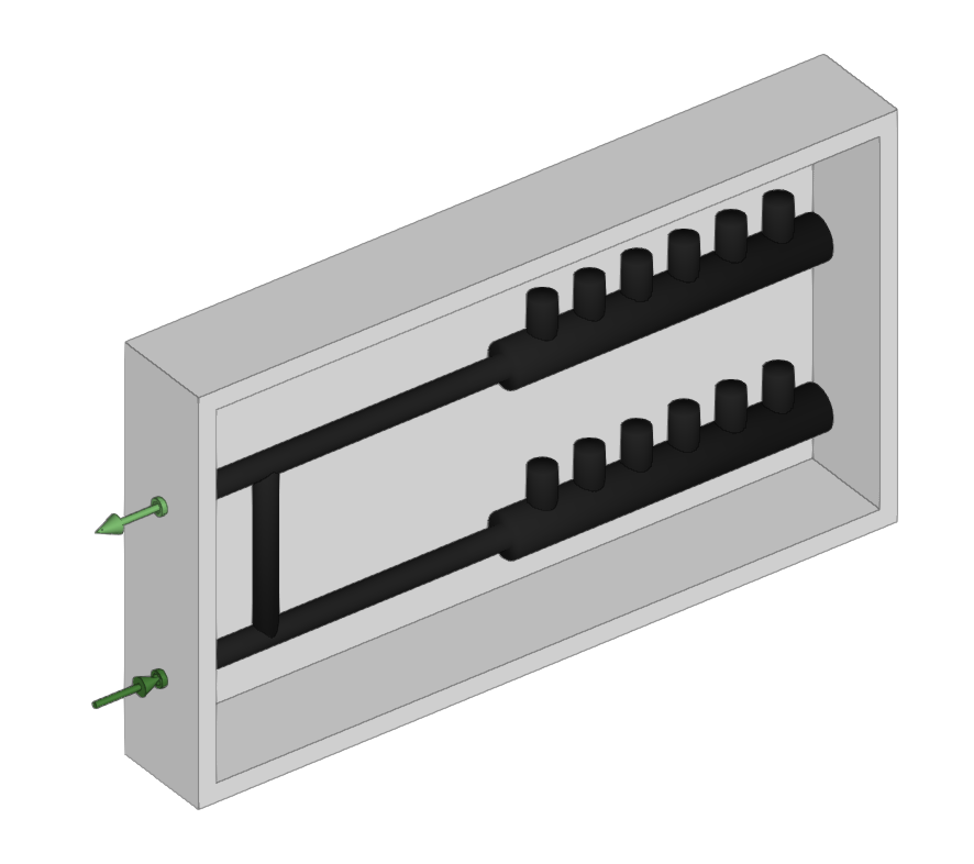
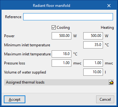
These manifolds will reach CYPEHVAC as requirements, which can be viewed if the corresponding layer in "Imported requirements" in the left-hand side panel "Own elements" is activated.
When using the "Radiant floor manifold" option, the program asks the user if they want to automatically generate manifolds at the position of the requirements. If accepted, it will automatically arrange the manifolds in the model and fill in their data by taking them from the imported requirements.
If not, users can enter the manifolds freely by snapping the requirements individually. When entering them, the program will ask users once again whether they wish to fill in their values by taking them from the requirement. If the user decides to enter the values manually and they do not cover the values required by the requirement, a non-compliance error will remain visible.
Entering DHW exchangers and cylinders
In the "Installation" tab, in the "DHW" menu of the "Water Heating" group in the main toolbar, the following elements can be defined and entered:

These elements link the air-conditioning system to the domestic hot water system.
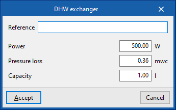
DHW exchanger
Enters DHW heat exchangers.
When entering a DHW heat exchanger, the following parameters must be specified:
- Reference
- Design conditions
- Power
- Pressure loss
- Capacity
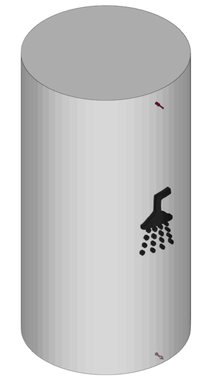
DHW cylinder
Enters DHW exchangers.
When entering a DHW exchanger, the following parameters must be specified:
- Reference
- Design conditions
- Power
- Pressure loss
- Water volume in the exchanger
- Dimensions
- Diameter
- Height
Entering domestic heat pump systems
Within the "System" tab, in the "Domestic heat pump" group of the main toolbar, there are options for defining and entering the following elements, which make up the different domestic heat pump systems covered by the program:

- Equipment
- Compact unit, monobloc domestic heat pump system
- Outdoor unit, bibloc domestic heat pump system
- Indoor unit with DHW tank, bibloc domestic heat pump system
- Indoor wall unit, bibloc domestic heat pump system
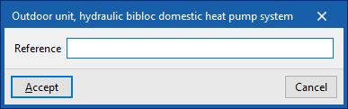
- Outdoor unit, hydraulic bibloc domestic heat pump system
- Indoor unit with DHW tank, hydraulic bibloc domestic heat pump system
- Indoor wall unit, hydraulic bibloc domestic heat pump system
- Refrigerant pipe
The following domestic heat pump systems are available:
Monobloc domestic heat pump system
A monobloc domestic heat pump system consists only of the following compact unit, available in the "Equipment" menu:
- Compact unit, monobloc domestic heat pump system
This unit is equipped with two connection sockets with water distribution pipes.
When entering a compact unit of a monobloc domestic heat pump system, the following parameters must be specified:
- Reference
- Catalogue / Series / Selection
Selects and imports data from previously uploaded manufacturer catalogues via the "Catalogue management" option. - 3D Model
3D view of the selected unit. - Nominal heating capacity / Nominal cooling capacity
Nominal capacities of the selected unit. - Design condition
- Supply temperature (Cooling (optional) / Heating (optional))
Temperature difference (Cooling (optional) / Heating (optional))
This figure is set by the program.

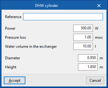
Bibloc domestic heat pump system
A bibloc domestic heat pump system consists of two elements, the outdoor unit and the indoor unit, available in the "Equipment" menu, connected by a refrigerant pipe:
- Outdoor unit
- Outdoor unit, bibloc domestic heat pump system
- Indoor unit
One of the following must be selected:- Indoor unit with DHW tank, bibloc domestic heat pump system
- Indoor wall unit, bibloc domestic heat pump system
The outdoor unit and the indoor unit must be connected to a "Refrigerant pipe" via the corresponding option in the "Domestic heat pump" group.
The indoor unit also has two connection sockets with water distribution pipes.
When the indoor unit is entered, the corresponding outdoor unit is simultaneously selected in the same editing panel, depending on the system. In this way, there is no need to enter any data for the outdoor unit when it is entered and only its layout in the space needs to be defined.
Therefore, when entering an outdoor unit of a bibloc domestic heat pump system, only the following parameter needs to be entered:
- Reference

When entering an indoor unit of a bibloc domestic heat pump system, the following parameters must be specified:
- Reference
- Catalogue / Series / Outdoor unit / Indoor unit
Selects and imports data from previously uploaded manufacturer catalogues via the "Catalogue management" option. - 3D Model
3D view of the selected unit. - Nominal heating capacity / Nominal cooling capacity / Refrigerant
Nominal capacities and type of refrigerant of the selected unit. - Design conditions
- Supply temperature (Cooling (optional) / Heating (optional))
Temperature difference (Cooling (optional) / Heating (optional))
This figure is set by the program.

Hydraulic bibloc domestic heat pump system
A bibloc domestic heat pump system consists of two elements, the outdoor unit and the indoor unit, available in the "Equipment" menu, connected by water distribution pipes:
- Outdoor unit
- Outdoor unit, hydraulic bibloc domestic heat pump system
- Indoor unit
One of the following must be selected:- Outdoor unit, hydraulic bibloc domestic heat pump system
- Indoor wall unit, hydraulic bibloc domestic heat pump system
The primary circuit can be laid by connecting the outdoor unit and the indoor unit with "Water distribution" pipes, which are available in the corresponding group. In this case, the pipe length limits, the difference in dimensions and the pipe diameter established by the manufacturer for the primary circuit must be checked.
The indoor unit also has two further connection sockets with water distribution pipes.
When the indoor unit is entered, the corresponding outdoor unit is simultaneously selected in the same editing panel, depending on the system. This way, there is no need to enter any data for the outdoor unit at the time of entry and only its layout in the space needs to be defined.
When inserting an outdoor unit of a hydronic bibloc domestic heat pump system, only the following parameter needs to be entered:
- Reference
When inserting an outdoor unit of a hydraulic bibloc domestic heat pump system, the following parameters must be specified:
- Reference
- Catalogue / Series / Outdoor unit / Indoor unit
Selects and imports data from previously uploaded manufacturer catalogues via the "Catalogue management" option. - 3D model
3D view of the selected unit. - Nominal heating capacity / Nominal cooling capacity
Nominal capacities of the selected unit. - Design conditions
- Supply temperature (Cooling (optional) / Heating (optional))
- Temperature difference (Cooling (optional) / Heating (optional))
This figure is set by the program.


Inserting components of the condensing circuit
Under the "Installation" tab, in the "Condensing" section of the main toolbar, you will find the menu for defining and entering the components of the condensing circuit:

These features enable the analysis of condensation circuits for water-to-water heat pumps. Based on their power and efficiency data, the program calculates the thermal power at the heat pump’s external heat exchanger and allows the hydraulic circuit to be defined right through to the equipment responsible for dissipating that power.
Generator
This allows you to add a heat source for the condensing circuit. This equipment acts as a heat source, such as a field of geothermal collectors.
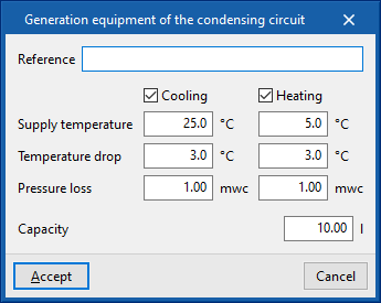
When adding a power generation unit, you must specify the following parameters:
- Reference
- Design specifications
- Supply temperature (Cooling (optional) / Heating (optional))
In a geothermal system, this refers to the temperature at which the fluid is pumped to the buried boreholes. - Temperature drop (Cooling (optional) / Heating (optional))
In a geothermal system, this refers to the difference between the temperature at which the fluid is pumped to the buried boreholes and the temperature at which it returns to the heat pump. - Pressure loss (Cooling (optional) / Heating (optional))
- Capacity
- Supply temperature (Cooling (optional) / Heating (optional))
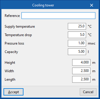
Cooling tower
Allows cooling towers to be installed.
When specifying a cooling tower, the following parameters must be provided:
- Reference
- Design specifications
- Supply temperature
- Temperature drop
- Pressure loss
- Capacity
- Dimensions
- Height
- Width
- Length

Entering equipment (water distribution)
In the "Installation" tab, in the "Equipment" menu of the "Water distribution" group in the main toolbar, the following elements can be defined and entered:

Fittings
Enters fittings for the water distribution system.
When entering fittings, the following parameters must be specified:
- Reference
- Selection
The program selects and imports data from the "Library of generic elements" using the wizard on the right-hand side.
Library of generic fittings
The "Library of generic elements" option, within the "Project" group, is used to create and edit the libraries of available generic fitting types.
The data associated with each type of fitting is as follows:
- Reference
- Description
- Graphical representation
Accesses the symbol library available from "General options" via "Symbols for drawings" in the "Project" group of the general interface. - Element pressure drop (Flow coefficient, Kv / Localised pressure loss)
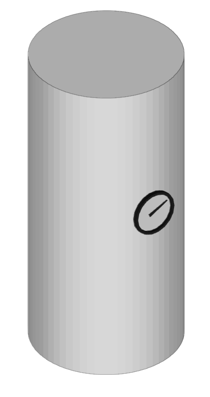
Accumulator tank
Inserts accumulator tanks.
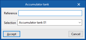
When entering accumulator tanks the following parameters must be indicated:
- Reference
- Selection
The program selects and imports data from the "Library of generic elements" using the wizard on the right-hand side.
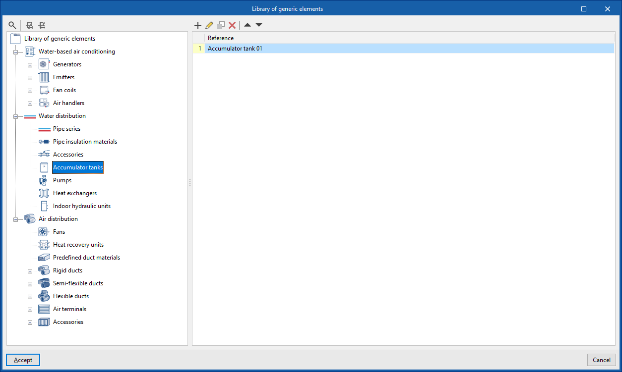
Library of generic accumulator tanks
The "Library of generic elements" option, within the "Project" group, is used to create and edit the libraries of available generic accumulator tank types.
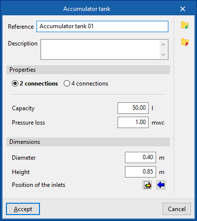
The data associated with each type of accumulator tank is as follows:
- Reference
- Description
- Characteristics
- 2 outlets (Capacity; Pressure loss)
- 4 outlets (Capacity; Pressure loss, primary circuit; Pressure loss, secondary circuit)
- Dimensions (Diameter; Height; Inlet position)
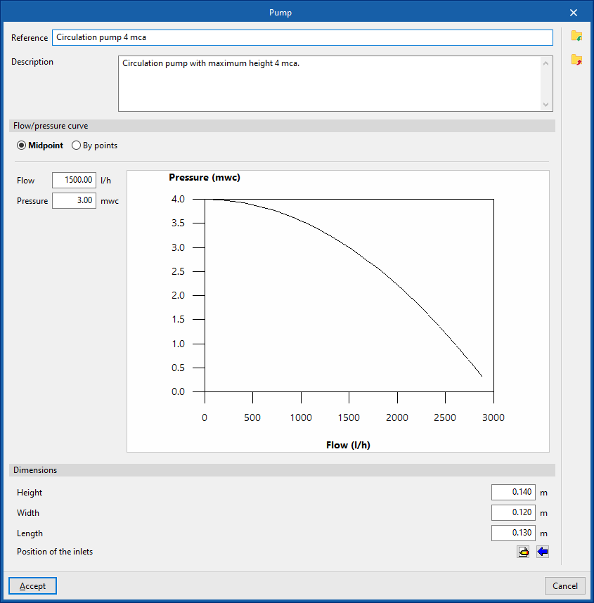
Pump
Inserts circulation pumps.
When entering a pump, the following parameters must be specified:
- Reference
- Selection
The program selects and imports data from the "Library of generic elements" using the wizard on the right-hand side.
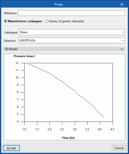
Library of generic pumps
The "Library of generic elements" option, within the "Project" group, is used to create and edit the libraries of available generic fitting types.
The data associated with each type of pump is as follows:
- Reference
- Description
- Flow/pressure curve
- Midpoint (Flow; Pressure)
- Dotted (Flow; Pressure)
- Dimensions (Height; Width; Length; Inlet position)
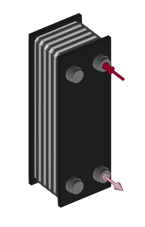
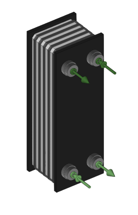
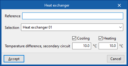
Heat exchanger
Inserts heat exchangers for the water distribution system.
When entering a heat exchanger, the following parameters must be specified:
- Reference
- Selection
The program selects and imports data from the "Library of generic elements" using the wizard on the right-hand side. - Temperature drop, secondary circuit (Cooling (optional); Heating (optional))
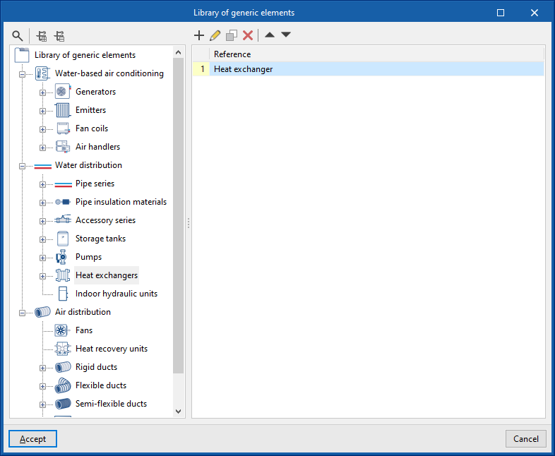
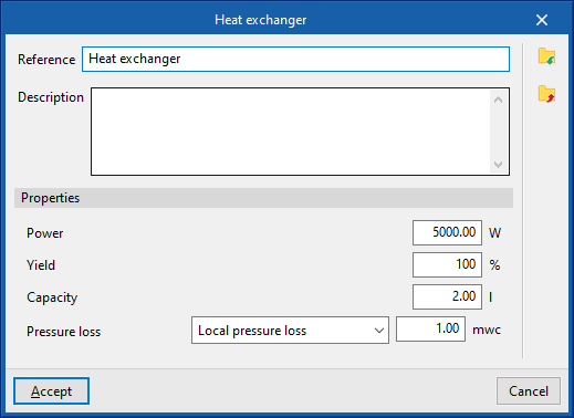
Library of generic heat exchangers
The "Library of generic elements" option, within the "Project" group, is used to create and edit the libraries of available generic fitting types.
The data associated with each type of heat exchanger is as follows:
- Reference
- Description
- Characteristics
- Power
- Performance
- Capacity
- Pressure loss (Localised pressure loss / Flow coefficient, Kv / Depending on the flow rate)
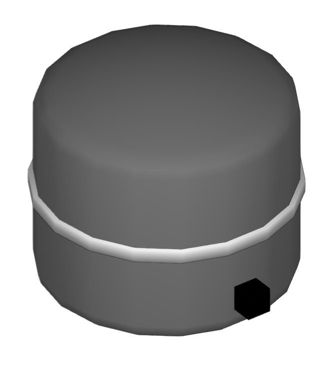
Expansion tank
Inserts expansion tanks.
When entering an expansion tank, the following parameters must be specified:
- Reference
- Type
- Open
Tank expansion vessel open to atmosphere. - Closed
Closed tank expansion vessel, containing a volume of air and water in contact with each other.
- Open
- Diaphragm
A diaphragm tank expansion vessel, which has a flexible inner membrane separating air and water.
By clicking on "Calculate", the program collects the minimum and maximum temperature and the volume of fluid in the system from the associated installation and provides the required capacity of the expansion tank according to its type.
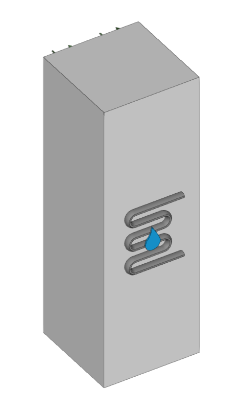
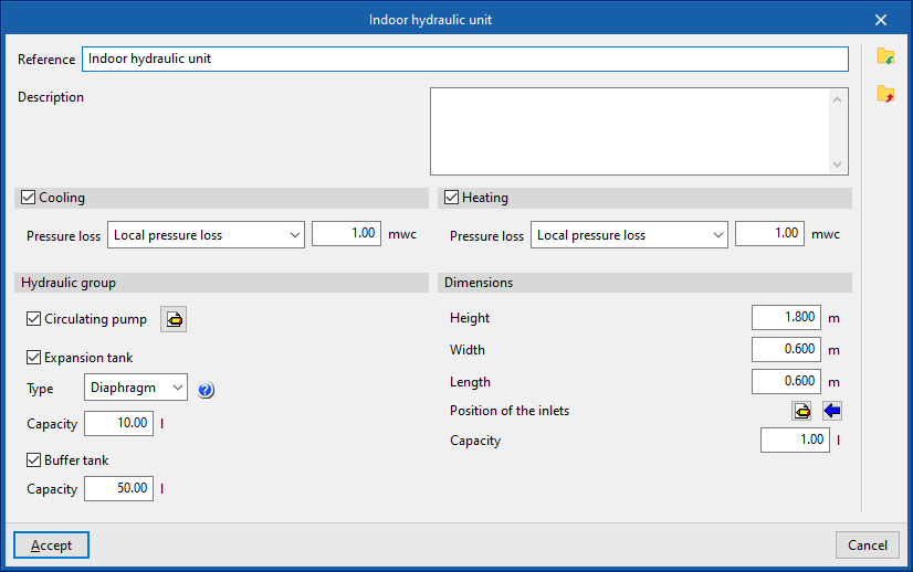
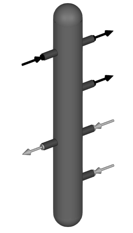
Indoor hydraulic unit
Enters indoor hydraulic units.
A hydronic indoor unit is a commercially available unit that brings together all the hydraulic fittings required in domestic aerothermal systems, such as the circulation pump, expansion tank or storage tank, under the same housing.
This means that to use these fittings, only this unit needs to be connected between the air-to-water heat pump and the circuit inside the building.
When entering a hydraulic indoor unit, the following parameters must be specified:
- Reference
- Selection
The program selects and imports data from the "Library of generic elements" using the wizard on the right-hand side. - Operating mode (Cooling (optional); Heating (optional))
Library of generic hydraulic indoor units
The "Library of generic elements" option, within the "Project" group, is used to create and edit the libraries of available generic fitting types.
The data associated with each type of hydraulic indoor unit are as follows:
- Reference
- Description
- Cooling (optional)
- Pressure drop (Localised pressure loss / Flow coefficient, Kv / Depending on the flow rate)
- Heating (optional)
- Pressure drop (Localised pressure loss / flow coefficient, Kv / Depending on the flow rate)
- Hydraulic unit
- Circulation pump (optional)
- Midpoint (Flow rate; Pressure)
- Point (Flow rate; Pressure)
- Expansion vessel (optional)
- Type (Open / Closed / Diaphragm)
- Capacity
- Inertia Accumulator (optional)
- Capacity
- Circulation pump (optional)
- Dimensions (Height; Width; Length; Position of inlets; Capacity)

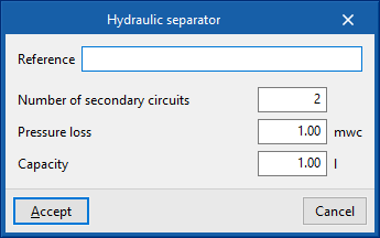
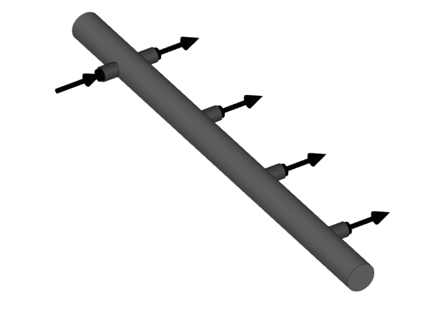
Hydraulic separator
Inserts hydraulic separators. This element allows the installation to be divided into independent circuits. The program calculates the pressure losses in each of these circuits separately.
When entering a hydraulic separator, the following parameters must be specified:
- Reference
- Number of secondary circuits
- Pressure loss
- Capacity
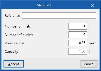
Manifold
Enters manifolds.
When entering a manifold, the following parameters must be specified:
- Reference
- Number of inlets
- Number of outlets
- Pressure loss
- Capacity
Entering pipes (water distribution)
Within the "Installation" tab, in the "Water distribution" group of the main toolbar, the following options are available to enter the pipes of the system:

Water pipe
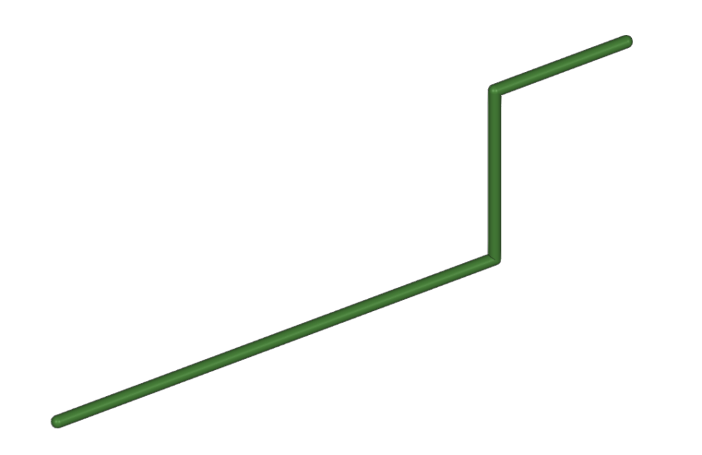
Water pipes can be entered in any direction by drawing them freely in any view of the model.
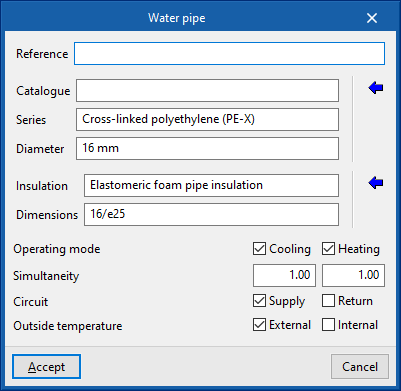
When entering a pipe, the following parameters must be specified:
- Reference
- Pipe selection
- The program selects and imports data from "Manufacturer catalogues" or from the "Library of generic elements" using the wizard on the right-hand side.
- Catalogue
- Series
- Diameter
- Selection of pipe insulation
- The program selects and imports data from the "Library of generic elements" using the wizard on the right.
- Insulation
- Dimensions
- Design conditions
- Operating mode (Cooling (optional); Heating (optional))
- Simultaneity (Cooling; Heating)
- Circuit (Supply (optional) / Return (optional))
- Outside temperature (Outdoor (optional) / Indoor (optional))
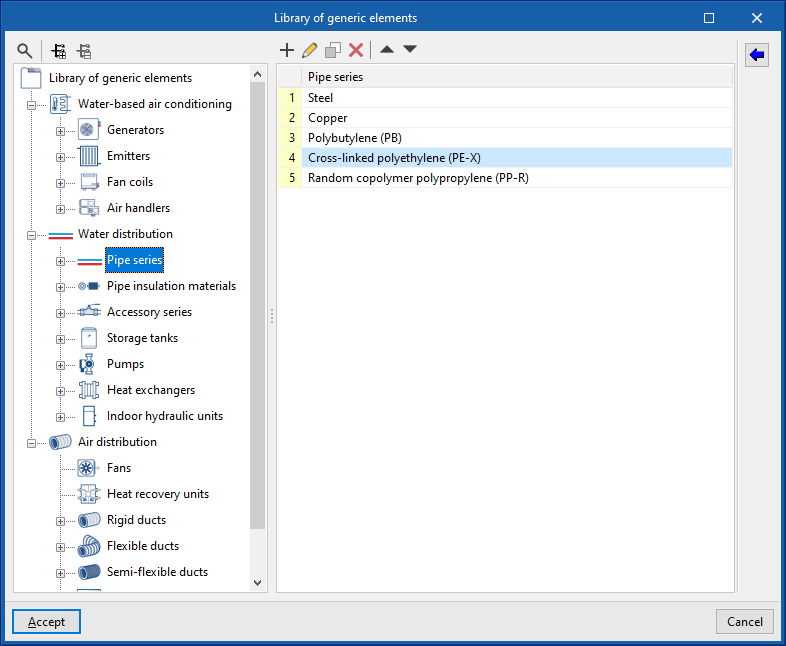
In the "Library of generic elements" option, within the "Project" group, the available generic pipe and insulation libraries can be created and edited.
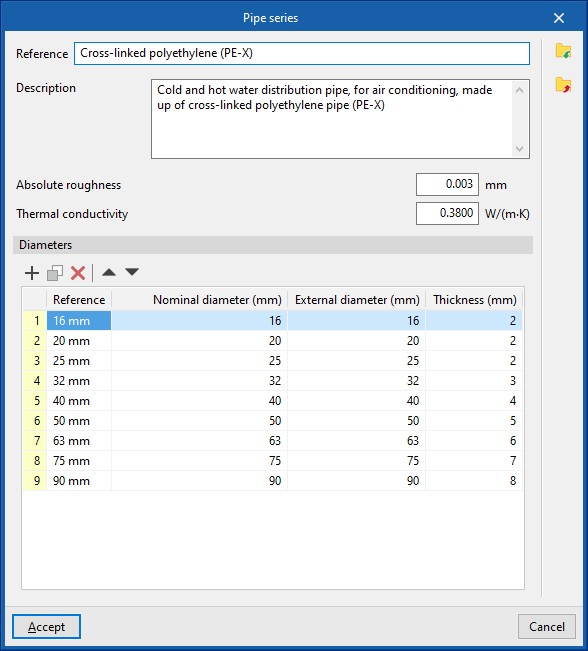
Pipe library
The data associated with each type of pipe is as follows:
- Reference
- Description
- Material
- Absolute roughness
- Thermal conductivity
- Diameters (Reference; Nominal diameter; External diameter; Thickness)
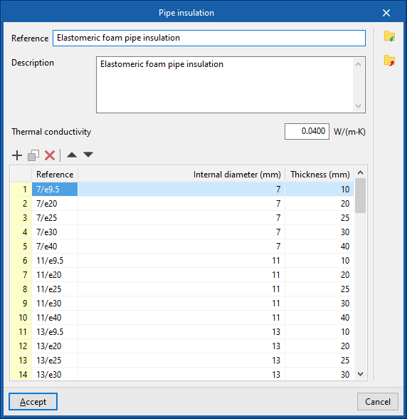
Insulation library
The data associated with each type of insulation is as follows:
- Reference
- Description
- Material
- Thermal conductivity
- Diameters (Reference; Internal diameter; Thickness)
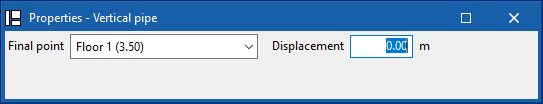
Vertical pipe
Inserts vertical pipes using the elevation of the plan views of the model as a support.
By clicking on this option, the program defines the characteristics of the pipe by means of an editing panel identical to the one that appears when using the "Pipe" option.
Then, in the "Properties - Vertical pipe" dialogue box, the level associated with the "End point" of the pipe is defined, together with a "Displacement" above the indicated level, expressed in positive or negative values. The starting point of the pipe is marked with the cursor on a point in the work area.
The pipe is then laid out from the working plane elevation of the active view, where the starting point has been marked, to the elevation defined by the selected level and the offset indicated in the dialogue box.

Pipe based on the existing pipe
This option inserts new pipes by taking the data from an existing pipe in the model.
To do this, first select the pipe from which the information will be extracted and accept the editing panel. The new pipe is then inserted into the model at the desired position.
Inserting VRF systems
Under the "Installation" tab, in the "VRF" menu within the "Direct expansion" section of the main toolbar, you will find the options for defining and entering the components of the variable refrigerant flow (VRF) systems supported by the program:

- VRF
- Outdoor unit, heat pump (2-pipe system)
- Outdoor unit with heat recovery (3-pipe system)
- Flowchart
- Manifold
- Referral
- Indoor unit, cassette
- Indoor unit, wall-mounted
- Indoor unit, floor-standing
- Indoor unit, ceiling
- Indoor unit, water production
- Indoor unit, with distribution using ducts
- Centralised control
- Automatic routing (VRF)
The available equipment and options are as follows:
Outdoor units
The options for installing the outdoor units of VRF systems and their associated components are as follows:
- Outdoor unit, heat pump (2-pipe system)
This unit supplies cooling to all indoor units simultaneously or heating to all indoor units simultaneously. - Outdoor unit, with heat recovery (3 pipe)
This unit is capable of providing cooling to some indoor units and heating to other indoor units simultaneously. To do this, a flow box must be installed upstream of each indoor unit. - Flow box
This device is used in systems with an outdoor unit featuring heat recovery (3-pipe system). Typically, one flow box is provided for each indoor unit, although it is also possible to supply several indoor units from a single flow box.
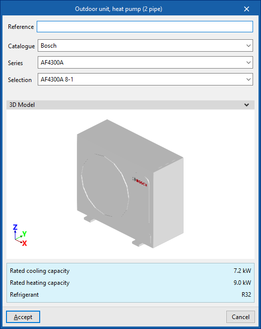
When adding an outdoor unit to a VRF system, the following parameters must be specified:
- Reference
- Catalogue / Series / Selection
Allows you to select and import data from manufacturer catalogues previously loaded using the "Catalogue management" option. - 3D model:
Three-dimensional view of the selected equipment. - Nominal heating capacity / Nominal cooling capacity / Refrigerant
Nominal capacities and type of refrigerant for the selected unit.


Indoor units
The options for installing indoor units for VRF systems are as follows:
- Indoor unit, cassette
- Indoor unit, wall-mounted
- Indoor unit, floor-standing
- Indoor unit, ceiling
- Indoor unit, water production
- Indoor unit, with distribution using ducts
This unit has two openings for air intake and exhaust, which can be connected by inserting air ducts from the options in the "Air Distribution" section.
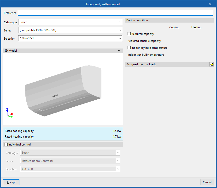
When installing an indoor unit for a VRF system, the following parameters must be specified:
- Reference
- Catalogue / Series / Selection
Allows you to select and import data from manufacturer catalogues previously loaded using the "Catalogue management" option. - 3D model:
Three-dimensional view of the selected equipment. - Nominal heating capacity / Nominal cooling capacity / Airflow (for "Indoor unit, ducted")
Specifications of the selected unit. - Individual control (optional)
Selecting this option enables individual control of the equipment.- Catalogue / Series / Selection
Allows you to select and import data from manufacturer catalogues previously loaded using the "Catalogue Management" option.
- Catalogue / Series / Selection
- Design specifications
- Power requirement (Cooling / Heating) (optional)
- Required apparent power (Cooling) (optional)
- Dry-bulb indoor temperature (Cooling / Heating) (optional)
- Internal wet-bulb temperature (Cooling) (optional)
- Check the maximum refrigerant charge (optional)
The "Space", "Area",
"Height" and "Volume" are displayed, indicating whether it is a "Basement".
The "R32 leak detector" checkbox allows you to specify whether the indoor unit is fitted with this component. This box will be ticked automatically if the "Add countermeasures automatically" option is enabled in the "General options". Furthermore, when an indoor unit already has a factory-fitted R32 detector, it will be ticked to make it easier for the user to understand.
- Assigned thermal loads
This allows you to define the following percentages of the heating and/or cooling thermal load values for the project. The program automatically assigns loads based on the layout of the terminal elements in the model.- % Rated heating power
- % Total rated cooling capacity
- % Rated cooling capacity
- % Heating load required
- % Total cooling load required
- % Required sensible cooling load


Manifolds and branches
These options allow you to configure the following components of a VRF system installation:
- Manifold
This allows a manifold to be installed between the outdoor unit and the indoor units. At certain points in the installation, the main pipe must supply several indoor units located at similar distances. In such cases, rather than using branch pipes that are very close to one another, it is advisable to install a manifold with 4 or 8 outlets. - Branch
Enters branches manually. The program automatically places a branch at all junctions where necessary. This option allows you to enter branches manually at the desired points.


| Note: |
|---|
| These units are connected to one another using the "Refrigerant line" option in the "Direct expansion" block. It is also possible to use the "Vertical pipe" option, specifying the elevation of the end point by selecting a floor and entering an offset, and marking a point in the workspace as the starting point. |
Centralised control
These options allow you to configure the centralised control of a VRF system:
- Reference
- Catalogue / Series / Selection
Allows you to select and import data from manufacturer catalogues previously loaded using the "Catalogue Management" option. - Units (Reference / Selection)
Allows you to select the outdoor units associated with the centralised control system.


Automatic routing (VRF)
This option allows you to select the units in the variable refrigerant flow (VRF) systems within the model and automatically generate the refrigerant piping layout between them. If necessary, you can subsequently adjust the generated piping layout using the element editing tools.

Entering direct expansion systems (multisplit and split 1x1)
Within the "Installation" tab, in the "Multisplit" and "Split" menus of the "Direct expansion" group in the main toolbar, there are options for defining and entering the elements of the multisplit and split 1x1 direct expansion systems covered by the program:

- Multisplit
- Outdoor multi-split unit
- Indoor unit, wall-mounted
- Indoor unit, with distribution using ducts
- Split
- Outdoor 1x1 unit
- Indoor 1x1 unit
The following systems are available:
Direct expansion multi-split system
This system consists of an outdoor unit connected to several indoor units.
Outdoor unit (multisplit)
The option to enter the outdoor unit of a multi-split direct expansion system is as follows:
- Multi-split outdoor unit
When entering an outdoor unit for a multi-split system, the following parameters must be specified:
- Reference
- Catalogue / Series / Selection
Selects and imports data from manufacturer catalogues previously uploaded using the "Catalogue management" option. - 3D model
3D view of the selected unit. - Nominal heating capacity / Nominal cooling capacity / Connected indoor units / Refrigerant
Nominal power ratings, connected indoor units, and refrigerant type of the selected unit.

Indoor units (multisplit)
The options for installing indoor units in multi-split systems are as follows:
- Multi-split indoor unit, wall-mounted
- Multi-split indoor unit, with duct distribution
When entering an indoor unit for a multi-split system, the following parameters must be specified:
- Reference
- Catalogue / Series / Selection
Selects and imports data from previously loaded manufacturer catalogues using the"Catalogue management" option. - 3D model
3D view of the selected unit. - Nominal heating capacity / Nominal cooling capacity / Capacity index
Properties of the selected unit. - Design conditions
- Power required (Cooling/Heating) (optional)
- Indoor dry bulb temperature (Cooling/Heating) (optional)
- Indoor wet bulb temperature (Cooling) (optional)
- Assigned thermal loads
Defines the following percentages on the values of the thermal loads for heating and/or cooling of the project. The program automatically assigns loads according to the layout of the terminal elements in the model.- % Assigned heating capacity
- % Assigned total cooling capacity
- % Assigned sensible cooling capacity
- % Required heating load
- % Required total cooling load
- % Required sensible cooling load

Direct expansion split system 1x1
This system consists of an outdoor unit and an indoor unit.
The options for installing the outdoor unit and indoor unit of a 1x1 direct expansion split system are as follows:
- 1x1 outdoor unit
- 1x1 indoor unit
When entering an outdoor unit for a 1x1 split system, only the following parameter needs to be specified:
- Reference
When entering an indoor unit for a 1x1 split system, the following parameters must be specified:
- Reference
- Catalogue / Series / Selection
Selects and imports data from previously loaded manufacturer catalogues using the"Catalogue management" option. - 3D model
3D view of the selected unit. - Nominal heating capacity / Nominal cooling capacity
Properties of the selected unit. - Design conditions
- Power required (Cooling/Heating) (optional)
- Indoor dry bulb temperature (Cooling/Heating) (optional)
- Indoor wet bulb temperature (Cooling) (optional)
- Assigned thermal loads
Defines the following percentages on the values of the thermal loads for heating and/or cooling of the project. The program automatically assigns loads according to the layout of the terminal elements in the model.- % Assigned heating capacity
- % Assigned total cooling capacity
- % Assigned sensible cooling capacity
- % Required heating load
- % Required total cooling load
- % Required sensible cooling load
Entering equipment (air distribution)
Within the "Installation" tab, in the "Equipment" menu of the "Air distribution" group in the main toolbar, the following elements can be defined and entered:

- Fan
- Heat recovery unit
- Fire damper
- Filter
- Airflow regulator
- Silencer
- Plenum
- Connection plate
- Cover
- Starting point for ductwork pre-installation
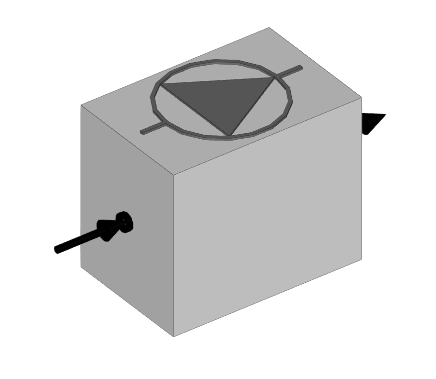
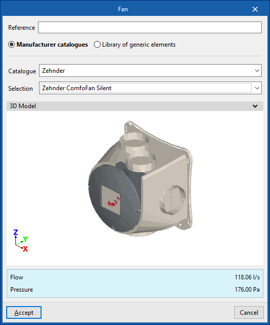
Fan
Enters fans.
When entering a fan, the following parameters must be specified:
- Reference
- Catalogue / Selection
The program can select and import data from "Manufacturer catalogues" or from the "Library of generic elements" using the wizard on the right-hand side.
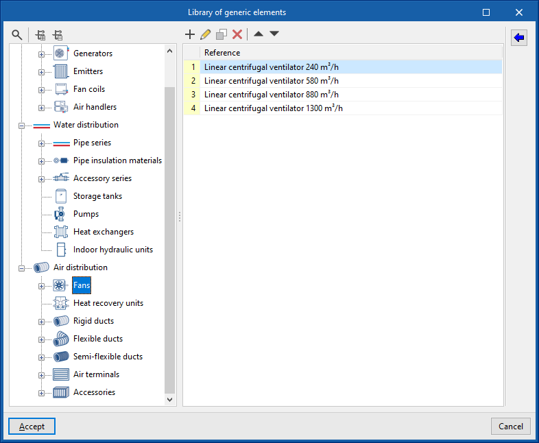
Library of generic fans
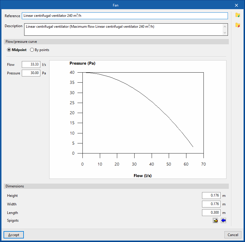
In the "Library of generic elements" option, within the "Project" group, the available library of generic fans can be created and edited.
The data associated with each type of fan is as follows:
- Reference
- Description
- Flow/pressure curve
- Midpoint (Flow; Pressure)
- By points (Flow; Pressure)
- Dimensions
- Height
- Width
- Length
- Spigots
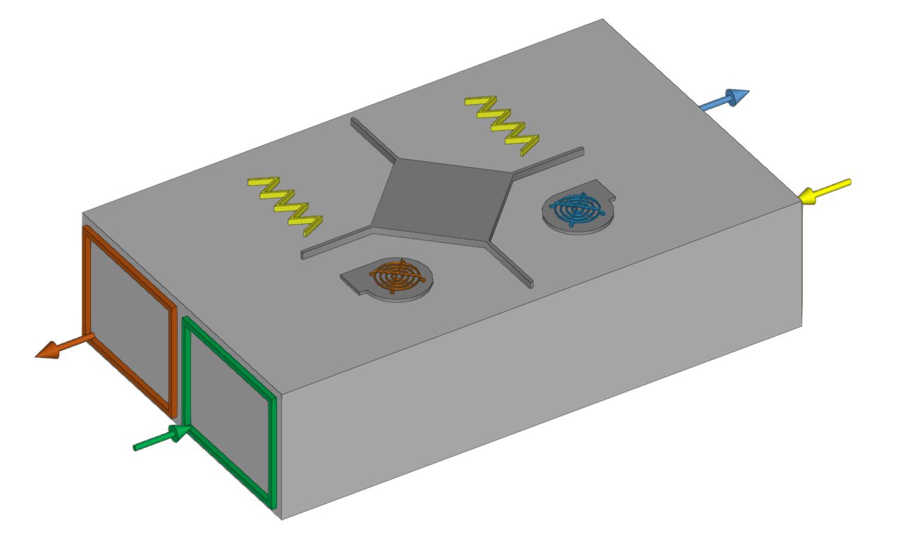
- Connections
- Installation
- Type of air flow (Outside air (ODA) / Supply air (SUP) / Exhaust air (ETA) / Discharge air (EHA) / Depending on the type of installation)
- The spigot can remain disconnected (optional)
- Geometry
- Type (Rectangular / Circular)
- Width x Height / Diameter
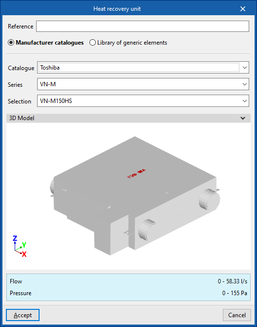
Heat recovery unit
Enters heat recovery units.
When entering a heat recovery unit, the following parameters must be specified:
- Reference
- Catalogue / Selection
The program can select and import data from "Manufacturer catalogues" or from the "Library of generic elements" using the wizard on the right-hand side.
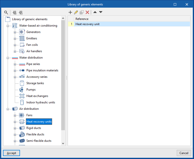
Library of generic heat recovery units
In the "Library of generic elements" option, within the "Project" group, the available library of generic heat recovery units can be created and edited.
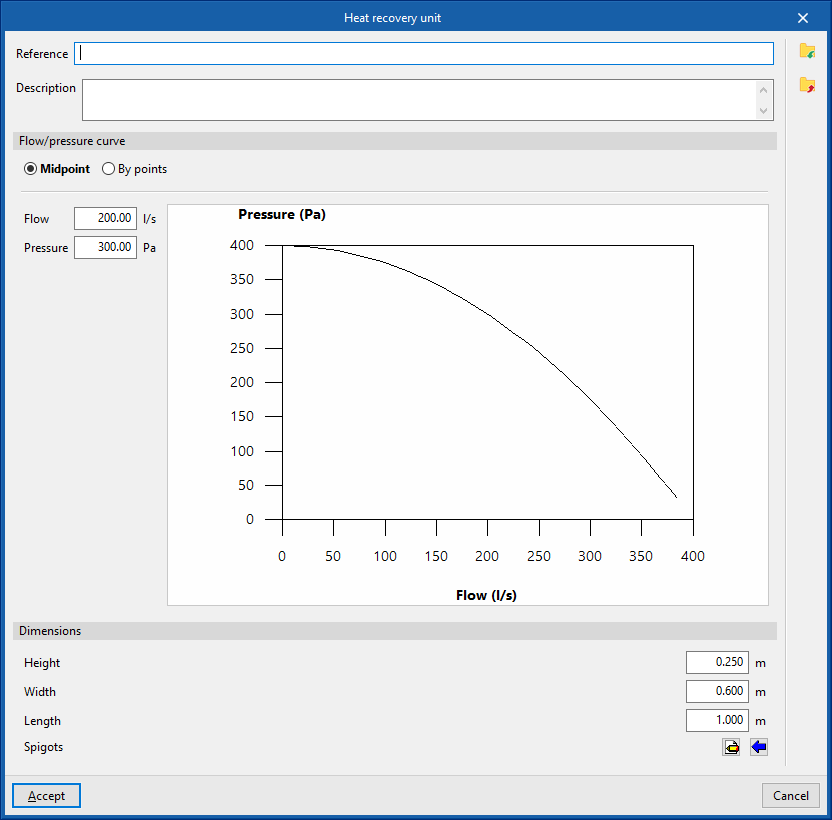
The data associated with each type of heat recovery unit are as follows:
- Reference
- Description
- Flow/pressure curve
- Midpoint (Flow; Pressure)
- By points (Flow; Pressure)
- Dimensions
- Height
- Width
- Length
- Spigots
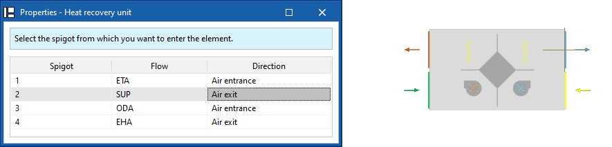
- Connections
- Installation
- Type of air flow (Outside air (ODA) / Supply air (SUP) / Exhaust air (ETA) / Discharge air (EHA) / Depending on the type of installation)
- The spigot can remain disconnected (optional)
- Geometry
- Type (Rectangular / Circular)
- Width x Height / Diameter
| Note: |
|---|
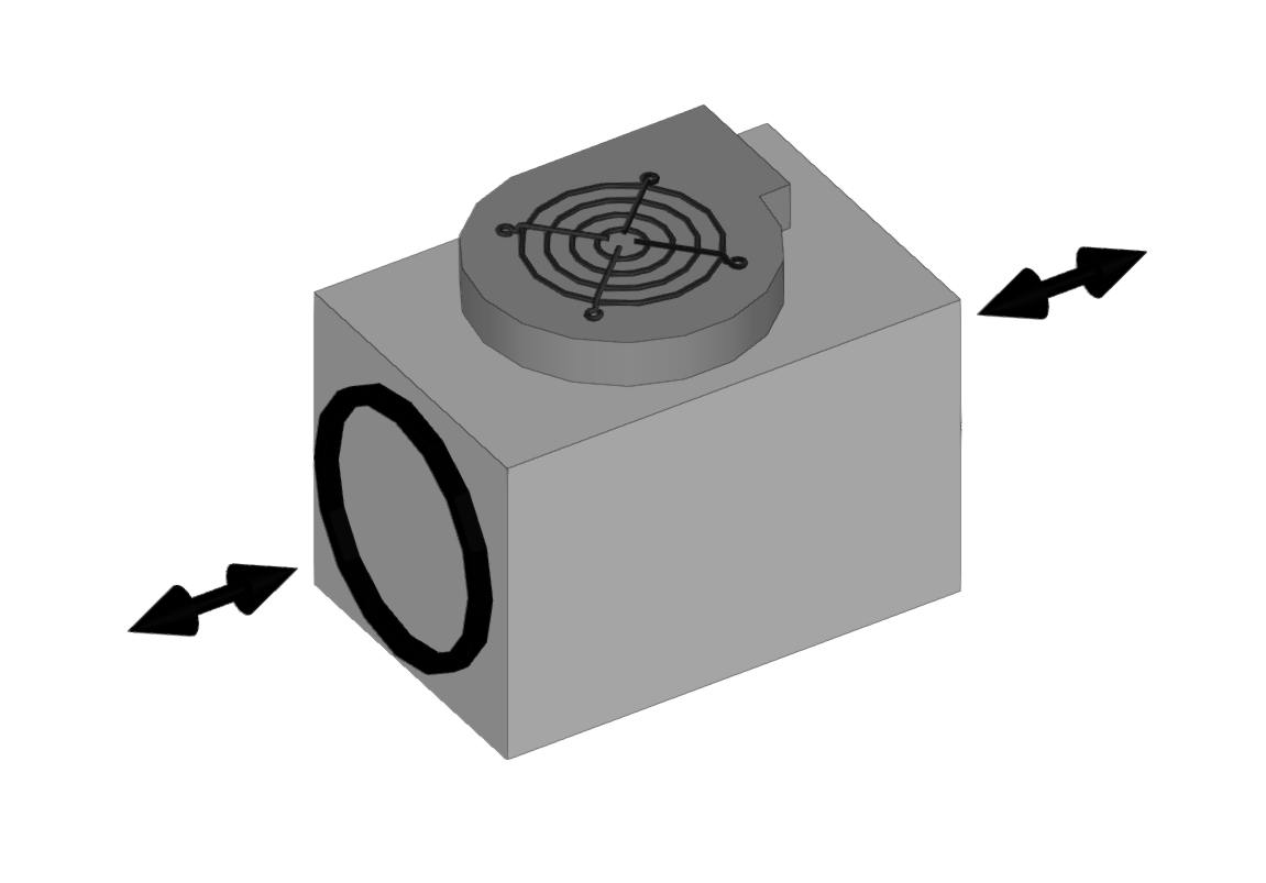
| When inserting air distribution system components, the program selects the inlet from which you wish to insert the component. The selected inlet will be positioned at the cursor's location. By pressing the "Space" key, you can change the orientation "Angle" of the component in plan view. This can also be modified using the options on the top bar of the "Work area" window. If you click on a duct end, the program will orient the unit to follow its direction. Once the equipment has been placed in position, you can rotate it about its axis by clicking on one of the four arrows that appear. These can be selected in turn by pressing the 'Space' key again. |
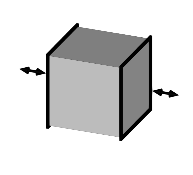
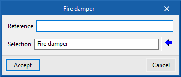
Fire damper
Inserts fire dampers.
When entering a fire damper, the following parameters must be specified:
- Reference
- Selection
The program can select and import data from "Manufacturer catalogues" or from the "Library of generic elements" using the wizard on the right-hand side.
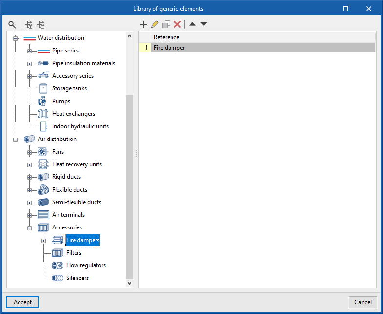
Library of generic fire damper
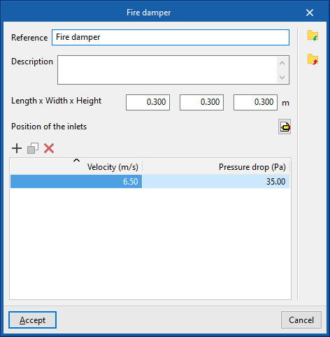
In the "Library of generic elements" option, within the "Project" group, the available library of generic fire dampers can be created and edited.
The data associated with each type of fire damper is as follows:
- Reference
- Description
- Dimensions
- Length x Width x Height
- Position of the inlets
- Sockets
- Type (Rectangular / Circular)
- Width x Height / Diameter
- Sockets
- Design values, depending on the flow
- Velocity; Pressure loss
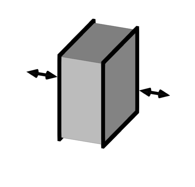
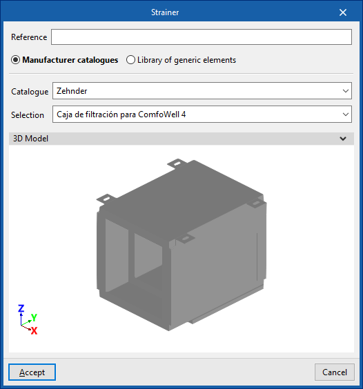
Strainer
Enters strainers.
When entering a strainer, the following parameters must be specified:
- Reference
- Catalogue / Selection
The program can select and import data from "Manufacturer catalogues" or from the "Library of generic elements" using the wizard on the right-hand side.
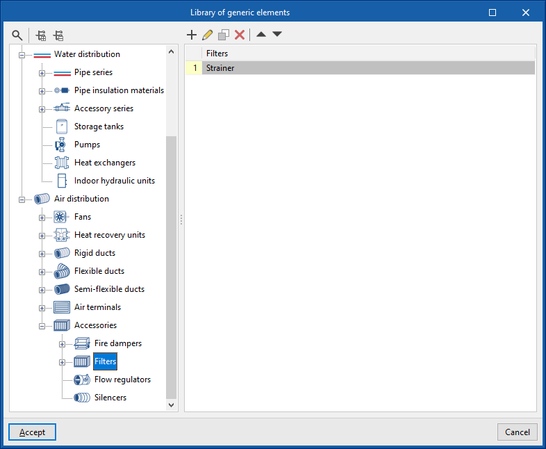
Library of generic strainers
In the "Library of generic elements" option, within the "Project" group, the available library of generic strainers can be created and edited.
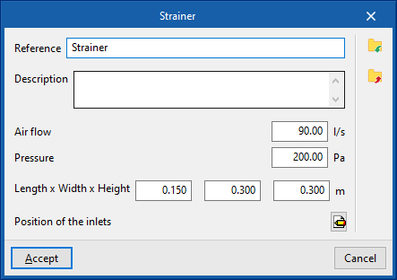
The data associated with each type of filter is as follows:
- Reference
- Description
- Air flow rate
- Pressure
- Dimensions
- Length x Width x Height
- Position of inlets
- Inlets
- Type (Rectangular / Circular)
- Width x Height / Diameter
- Inlets
Flow regulators
Enters flow regulators.
When entering a flow regulator, the following parameters must be specified:
- Reference
- Catalogue / Selection
The program can select and import data from "Manufacturer catalogues" or from the "Library of generic elements" using the wizard on the right-hand side.
Library of generic flow regulators
In the "Library of generic elements" option, within the "Project" group, the available library of generic flow regulators can be created and edited.
The data associated with each type of flow regulator is as follows:
- Reference
- Description
- Dimensions
- Length x Width x Height (m)
- Position of inlets
- Inlets
- Type (Rectangular / Circular)
- Width x Height / Diameter
- Inlets
- Design values, depending on the flow
- Air flow rate; Pressure loss
Silencer
Enters silencers.
When entering a silencer, the following parameters must be specified:
- Reference
- Catalogue / Selection
The program can select and import data from "Manufacturer catalogues" or from the "Library of generic elements" using the wizard on the right-hand side.
Library of generic silencers
In the "Library of generic elements" option, within the "Project" group, the available library of generic silencers can be created and edited.
The data associated with each type of silencer is as follows:
- Reference
- Description
- Dimensions
- Length x Width x Height (m)
- Position of inlets
- Inlets
- Type (Rectangular / Circular)
- Width x Height / Diameter
- Inlets
- Design values, depending on the flow
- Air flow rate; Pressure loss
Plenum
Inserts plenums in duct systems.
When entering a plenum, the following parameters must be specified:
- Reference
- Catalogue / Selection
Selects and imports data from previously loaded manufacturer's catalogues using the "Catalogue management" option. - 3D Model
- Three-dimensional visualisation of the selected equipment.
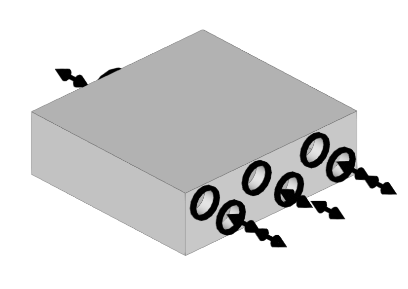
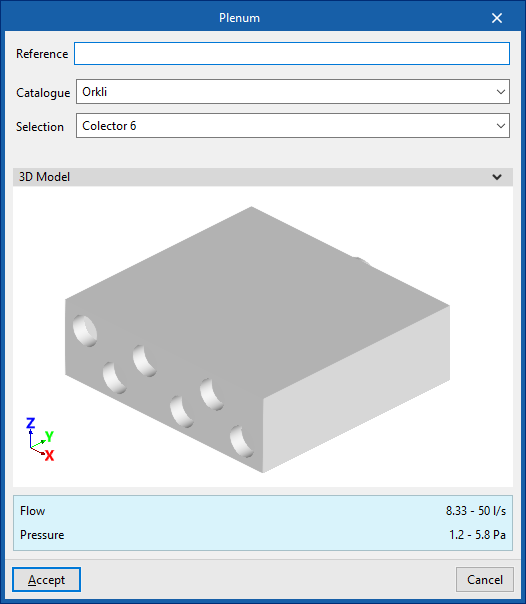
End piece
Used to insert end pieces into ductwork systems.
These components are used by some manufacturers where plenums and silencers do not have openings for circular ducts, as they allow for different connection systems.
Thus, depending on the connection plate used, a single plenum or silencer can be connected to a greater or lesser number of circular ducts, as well as to ducts of different cross-sections.
When fitting an end piece, the following parameters must be specified:
- Reference
- Catalogue / Selection
Selects and imports data from manufacturer catalogues previously uploaded using the "Catalogue Management" option. - 3D model
Three-dimensional view of the selected equipment.
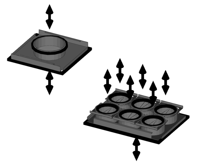
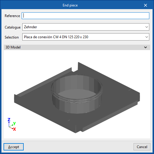
Cap
Inserts caps into ductwork installations.
These caps are fitted to the unused outlets of components that have multiple outlets (such as "End piece", "Plenum" or "Plenum for air outlet").
When inserting a cap, the following parameters must be specified:
- Reference
- Catalogue / Selection
Selects and imports data from manufacturer catalogues previously uploaded using the "Catalogue Management" option. - 3D model
Three-dimensional view of the selected equipment.
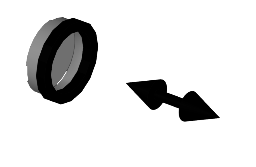
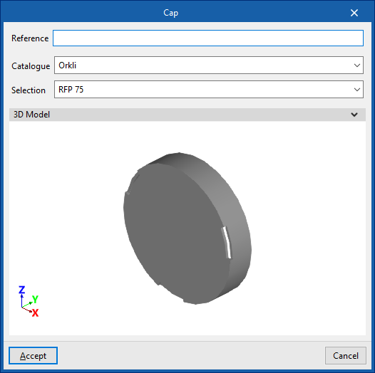
| Note: |
|---|
| Semi-flexible ducts must always be fitted with an end fitting. It makes no sense to fit a cap to a semi-flexible duct; therefore, unless necessary, the semi-flexible duct should not be installed, but the corresponding outlet on the connection plate, plenum or outlet plenum should be capped directly. Furthermore, the program automatically places caps at the ends of the ducts during calculation, so it is not necessary to use this option in such cases. |
Initial point of the duct pre-installation
This places the initial point of a duct pre-installation in the program. This way, the ductwork does not need to be connected to a machine or ventilation system for the analysis to be carried out.
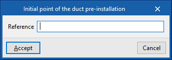
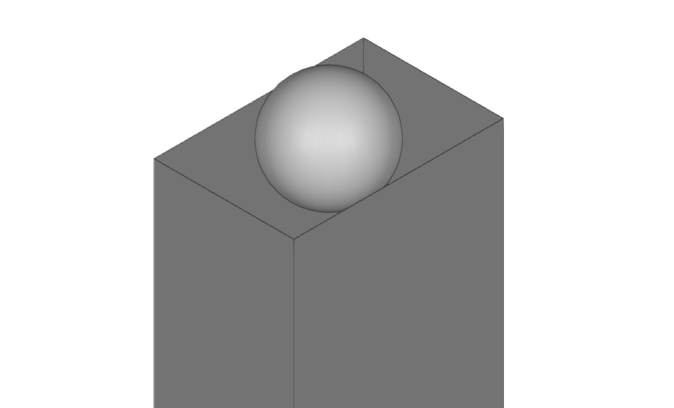
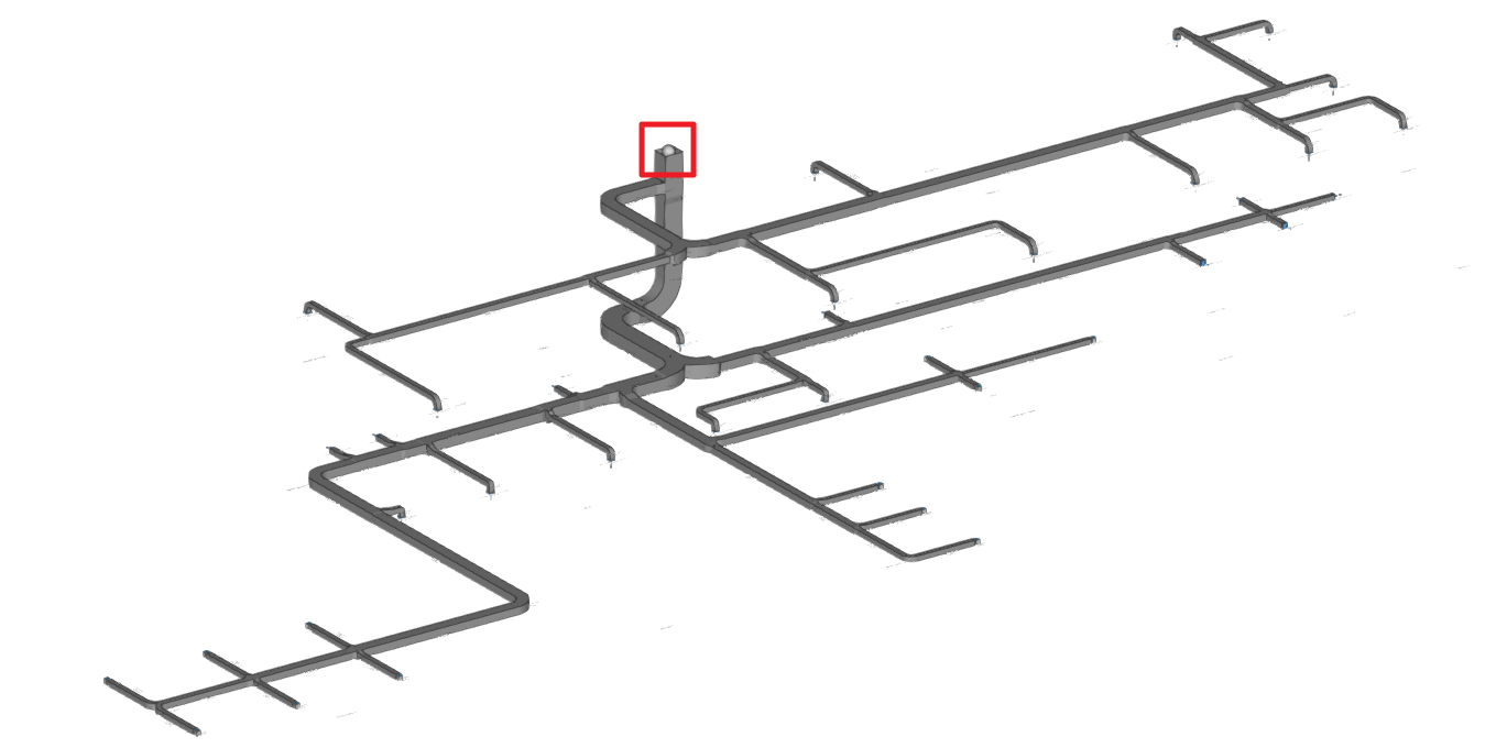
Entering ducts (air distribution)
Within the "Installation" tab, in the "Ducts" menu of the "Air distribution" group in the main toolbar, there are options for entering the air duct spans in the installation:

- Rigid conduit
- Semi-flexible conduit
- Flexible duct
Rigid duct / Semi-flexible duct / Flexible duct
These options allow the insertion of rigid, semi-flexible and flexible air ducts, respectively.
When entering a duct, the following parameters must be specified:
- Reference
- Type of duct
- Rectangular, custom (only for “Rigid ducts”) / Rectangular section / Circular section
- Catalogue selection
- Catalogue
- Material
- Selection
- Duct dimensions
- Width / Height (only for “Rectangular, custom”)
By activating the "Width" and/or "Height" checkboxes, the dimensions of the air ducts can be forced so that they are not modified by the program during the analysis.
- Width / Height (only for “Rectangular, custom”)
Data can be selected and imported from the "Manufacturer catalogues" or the "Library of generic elements" using the assistant available on the right-hand side of the program.
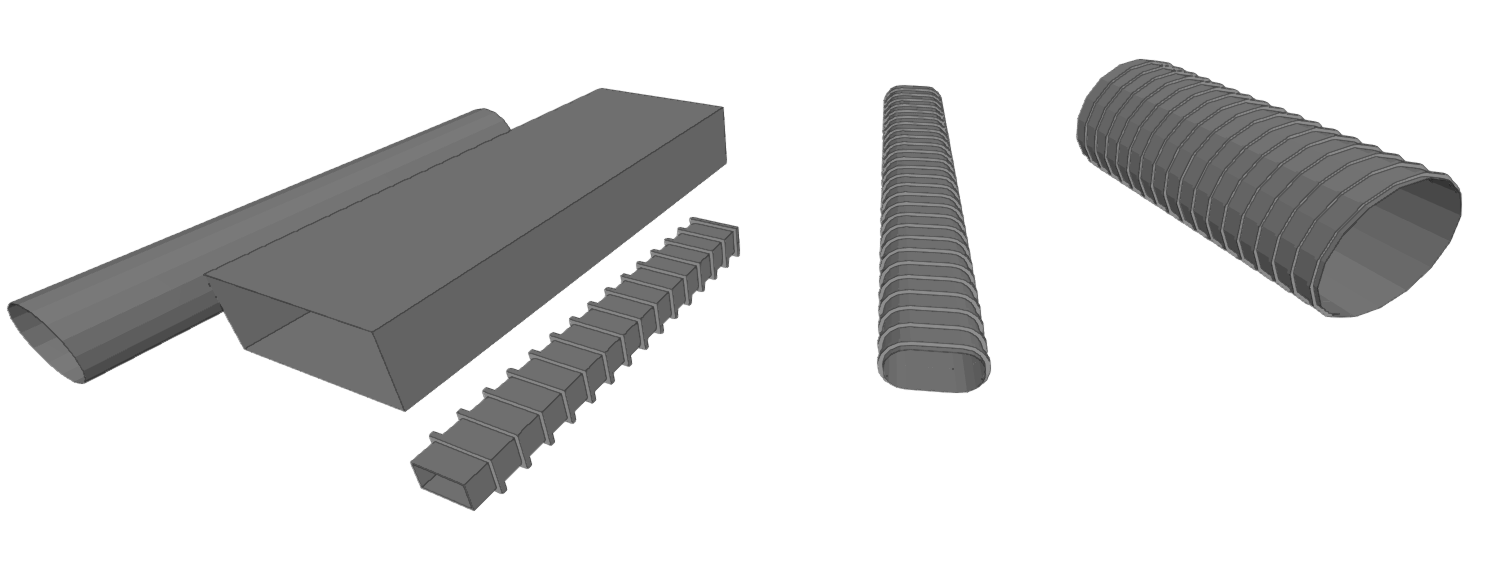
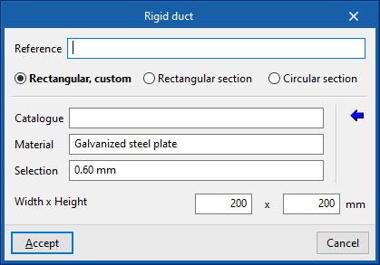
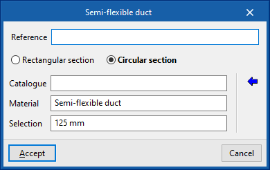
Library of generic elements
In the "Library of generic elements" option, in the "Project" group, generic duct libraries can be created and edited.
The data associated with each type of duct, regardless of whether they are rigid, semi-flexible or flexible, is as follows:
- Reference
- Description
- Roughness coefficient
- Rectangular ducts, custom
- Reference
- Thickness
- Rectangular ducts
- Reference
- Height
- Width
- Thickness
- Circular ducts
- Reference
- Diameter
- Thickness
Duct ends must be connected to other ducts, or ventilation unit or air terminal must be incorporated into the ducts.
If the entire ductwork system has terminal elements and is closed at all ends except one, a "Initial point of the duct pre-installation" must be provided at that end (available in the "Equipment" menu of the "Air distribution" group) so that the program interprets this situation and does not require the addition of a supply air machine.
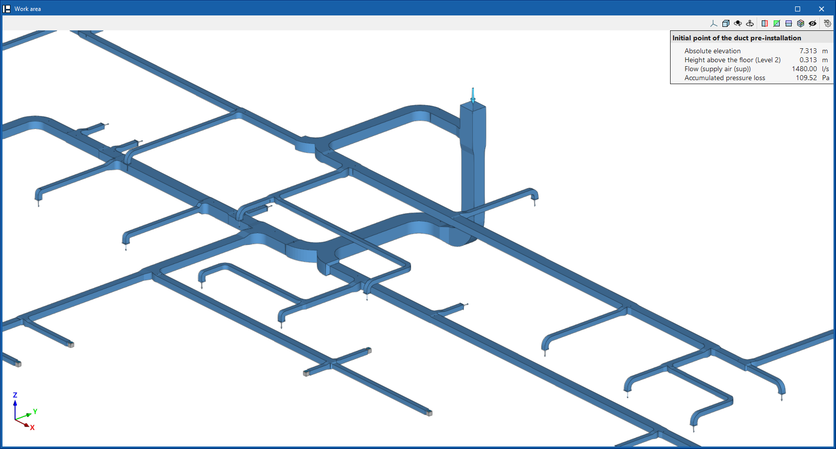
In the design process, the program analyses the layout and connections of the installation. It categorises the ducts as "Supply air (SUP)" (blue), "Discharge air (EHA)" (red), "Exhaust air (ETA)" (yellow) or "Outdoor air (ODA)" (green) and displays them with the colour that determines their category. This category can also be seen in the information text that appears when hovering over each duct.
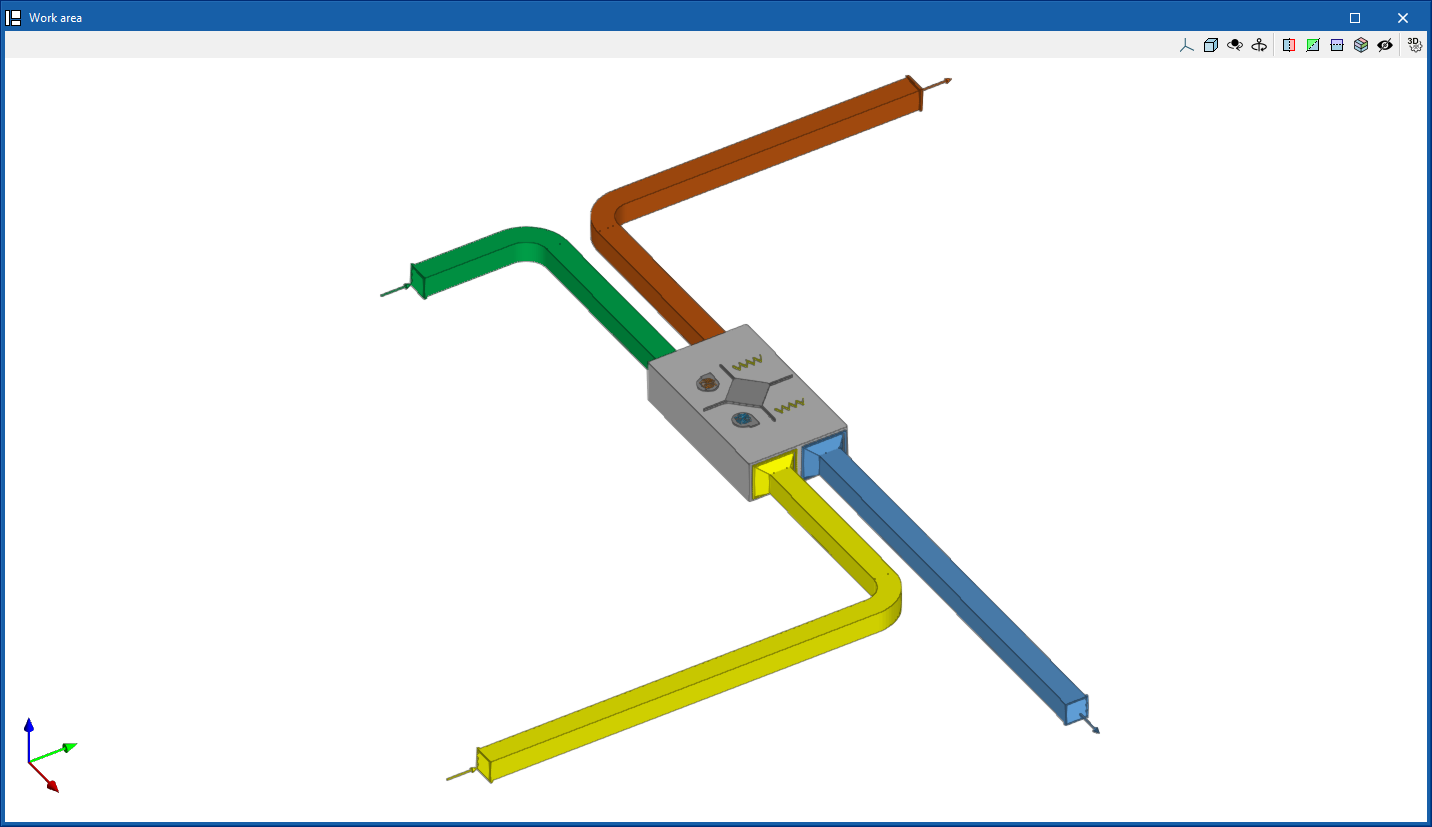
Inserting and generating fittings (air distribution)
In the "Installation" tab, in the "Air distribution" group of the main toolbar, there is a "Fittings" menu:

The options in this menu allow users to enter air duct connections by hand or to generate them automatically. The program includes the ASHRAE catalogue of elbows, transitions and branches as well as manufacturer catalogue fittings. These options are:
Generate fittings
Automatically generates the fittings in the air ducts. In doing so, the length of the duct sections reaching each fitting is adjusted.
For this purpose, the most appropriate type of fitting, whether elbows, transitions or branches, is sought and arranged according to the situation.
The generation of fittings is also integrated in the process that launches the "Design" option.
Delete fitting
This deletes the fittings. In doing so, the duct sections are lengthened so that they are not disconnected, thus taking the place of each eliminated connection.
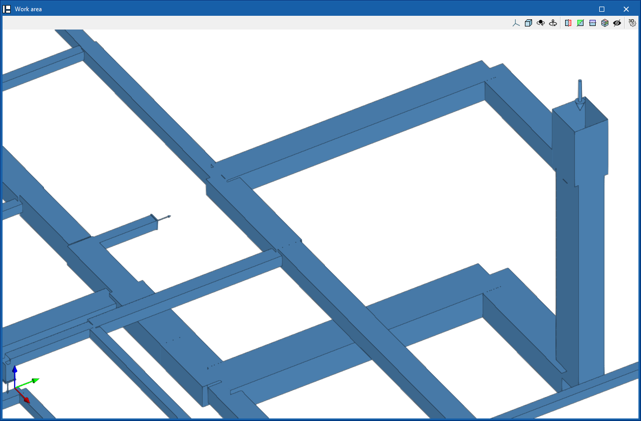
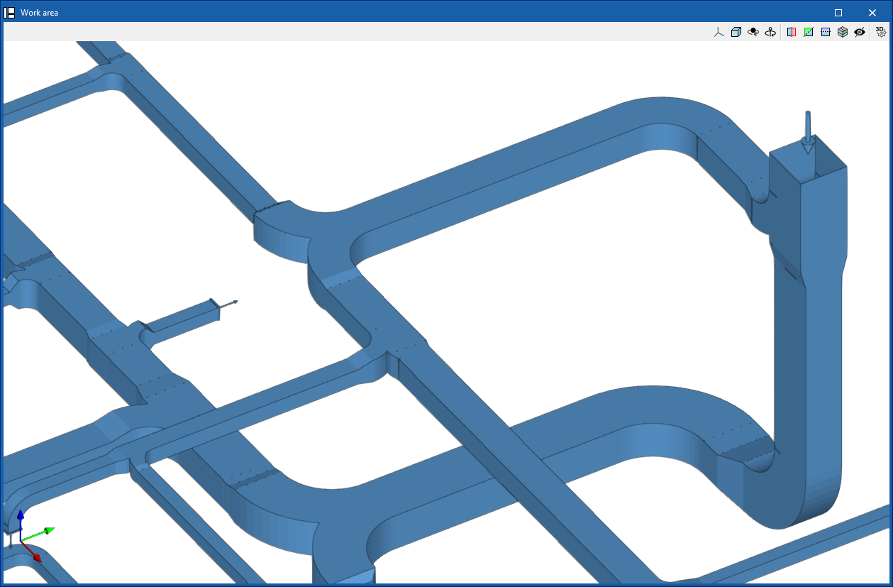
Elbow
Enters an elbow.
When entering an elbow the following parameters must be specified:
- Reference
- Generic
Defines a generic connection.- Catalogue / Material / Selection
Selects and imports duct data from "Manufacturer catalogues" or from the "Library of generic elements" using the wizard on the right. - Type
- Rectangular
- Circular
- Catalogue / Material / Selection
- Manufacturer catalogues
Selects and imports fittings from manufacturer catalogues using the wizard on the right.- Catalogue / Selection
Transition
Enters a transition.
When entering a transition the following parameters must be specified:
- Reference
- Generic
Defines a generic connection.- Catalogue / Material / Selection
Selects and imports duct data from "Manufacturer catalogues" or from the "Library of generic elements" using the wizard on the right. - Type
- Rectangular - Rectangular
- Rectangular - Circular
- Circular - Rectangular
- Circular - Circular
- Catalogue / Material / Selection
- Manufacturer catalogues
Selects and imports fittings from manufacturer catalogues using the wizard on the right.- Catalogue / Selection
Branch
Enters a branch.
When entering a branch the following parameters must be specified:
- Reference
- Generic
- Defines a generic connection.
- Catalogue / Material / Selection
Selects and imports duct data from "Manufacturer catalogues" or from the "Library of generic elements" using the wizard on the right. - Type
- Rectangular
- Circular
- Catalogue / Material / Selection
- Manufacturer catalogues
Selects and imports fittings from manufacturer catalogues using the wizard on the right.- Catalogue / Selection
Double branch
Enters a double branch.
When entering a branch the following parameters must be specified:
- Reference
- Generic
- Defines a generic connection.
- Catalogue / Material / Selection
Selects and imports duct data from "Manufacturer catalogues" or from the "Library of generic elements" using the wizard on the right. - Type
- Rectangular
- Circular
- Catalogue / Material / Selection
- Manufacturer catalogues
Selects and imports fittings from manufacturer catalogues using the wizard on the right.- Catalogue / Selection
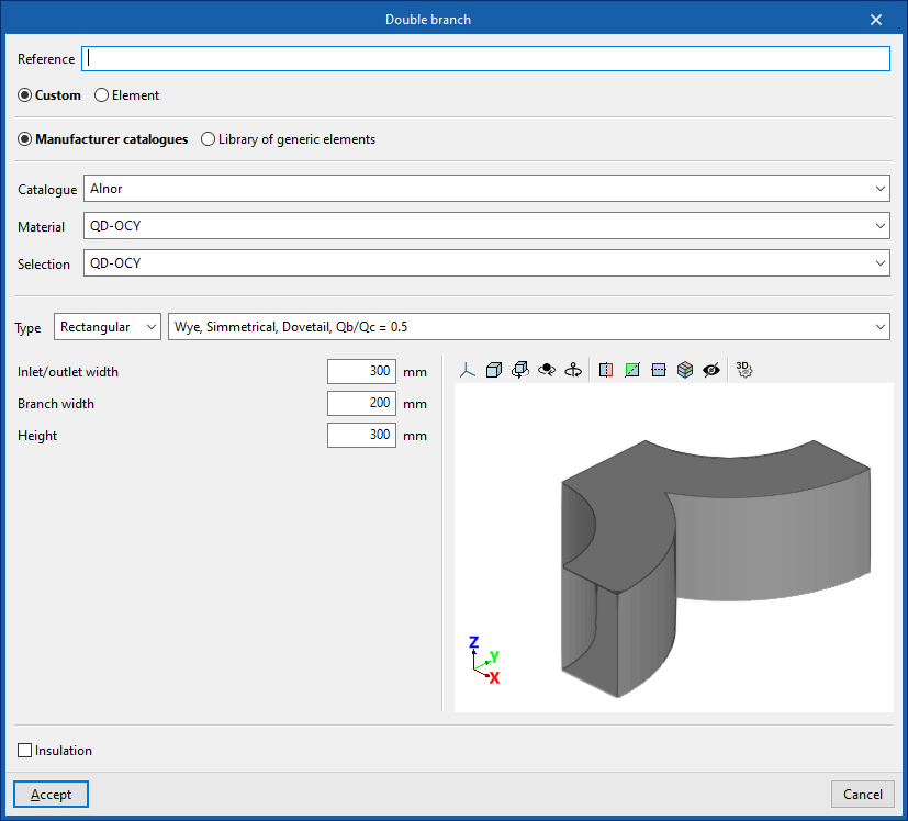
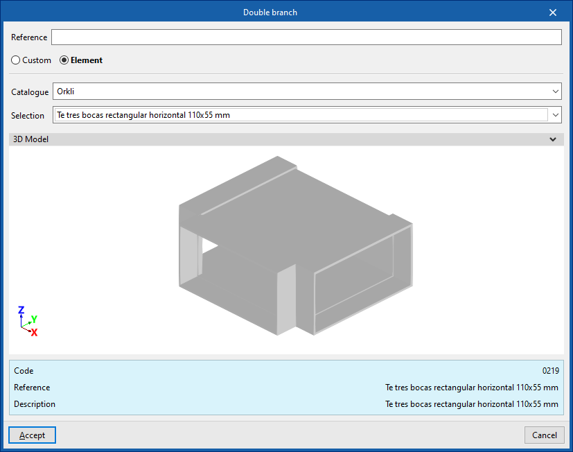
Triple branch
Enters a triple branch.
When entering a branch the following parameters must be specified:
- Reference
- Generic
Defines a generic connection.- Catalogue / Material / Selection
Selects and imports duct data from "Manufacturer catalogues" or from the "Library of generic elements" using the wizard on the right. - Type
- Rectangular
- Circular
- Catalogue / Material / Selection
- Manufacturer catalogues
Selects and imports fittings from manufacturer catalogues using the wizard on the right.- Catalogue / Selection
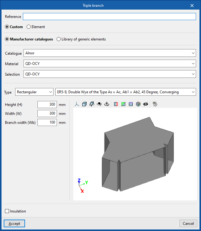
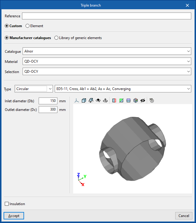
Editing tools
In the "Edit" group of the main toolbar, under the "Installation" tab, there are several tools for editing the installation:

The tool area of this group allows the following operations to be performed:
| Edit | Edit the parametric properties of the element selected in the model. | |
| Delete | Delete a previously entered element. | |
| Modify height position | Modify the height position of an element by specifying a relative displacement or absolute elevation. | |
| Move | Move an element or an element’s node. | |
| Move a group of elements | Move a group of elements. | |
| Measure length | Measure lengths between defined points on the model. If a closed contour is selected, it also indicates the area. | |
| Copy onto another floor plan | Create a copy of the selected elements in the desired floor plans. This feature is only available on floor plans. | |
| Rotate | Rotate an element about the "x", "y" or "z" axis. | |
| Rotate a group of elements | Rotate a group of elements. | |
| Copy | Create a copy of one or more elements. | |
| Assign | Assign the parametric properties of the selected element to other elements. | |
| Symmetry (copy) | Copy a selection of elements with symmetry with respect to a vertical plane defined by two points. | |
| Symmetry (move) | Move a selection of elements with symmetry about a vertical plane defined by two points. | |
| Divide | Divide pipes or air ducts into several sections. | |
| Extend/trim element | Extend or trim an element (pipe, refrigeration line, or duct) relative to another reference element. The first element acts as the reference, while the second is either extended or trimmed after the option is used. | |
| Extend/Trim to Intersection | Extends or trims two selected elements (pipes, refrigeration lines, or ducts) to their point of intersection. | |
| Join | Joins the selected ducts into a single segment. | |
| Annotations | Inserts a free annotation. |
Managing labels
The following tools are located in the "Labels" group of the main toolbar under the "Installation" tab:

Move labels
Moves the labels of the elements in the system.
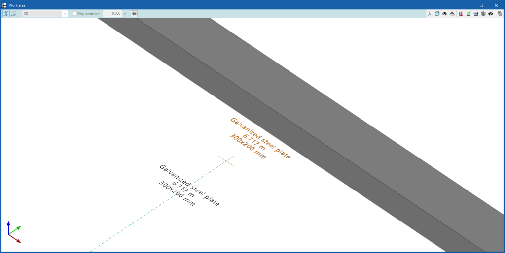
Show/hide label
Activates or deactivates the visibility of the labels of the selected elements in the system.
Show/hide labels
Activates or deactivates the visibility of labels for all elements in the system.
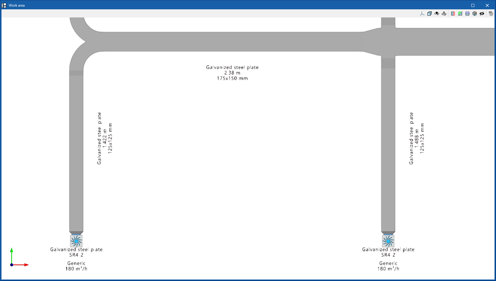
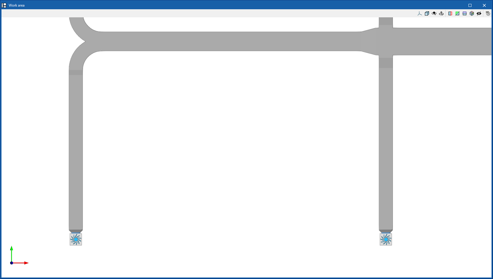
Importing and assigning thermal loads
The "Thermal loads" group in the main toolbar, under the "Installation" tab, contains the tools for managing the thermal loads of the model:

Importing thermal loads from the BIM mode
CYPEHVAC can import the thermal loads per space calculated in programs such as CYPETHERM LOADS from the BIMserver.center project information.
These loads are represented in the model view by specific symbols, which are visible if the corresponding layer is activated in the "Own elements" panel, located by default on the left-hand side (by accessing "Imported requirements" and "Thermal loads").

Entering and editing thermal loads
Thermal loads can be entered and edited directly in CYPEHVAC using the table accessible from the "Assign" or "Edit" icons in the "Thermal loads" group in the upper toolbar.
Loads can be defined with a total value or by their value per unit area:
- Total thermal load (kW)
- Thermal load per unit area (W/m2)
- Area
The following parameters can be defined for cooling loads and heating loads:
- Cooling
- Total cooling load
- Sensible cooling load
- Indoor design temperature
- Relative humidity
- Heating
- Heating load
- Indoor design temperature
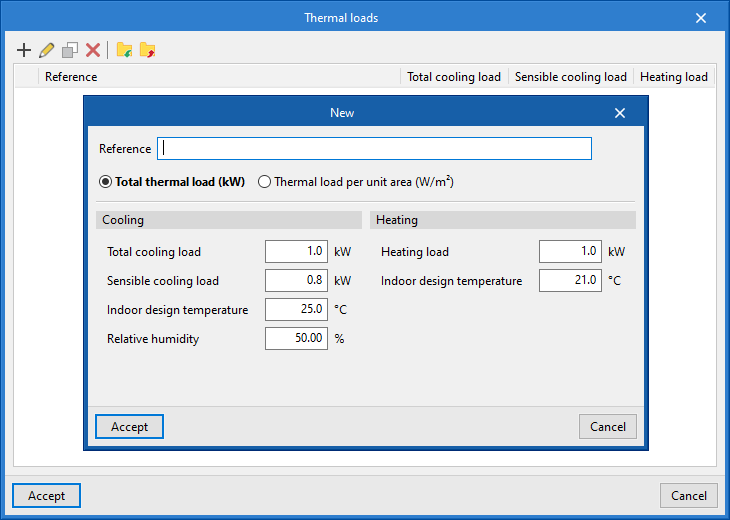
Assigning thermal loads
Automatically assigning heat loads
If a thermal load is imported into a space defined in the BIM model and there are one or more terminal elements in that space (e.g. radiators), the program performs the load assignment automatically.
The combined power of these elements will appear as "Installed power" in the thermal load of the space, so the program can check if it is enough to cover the load.
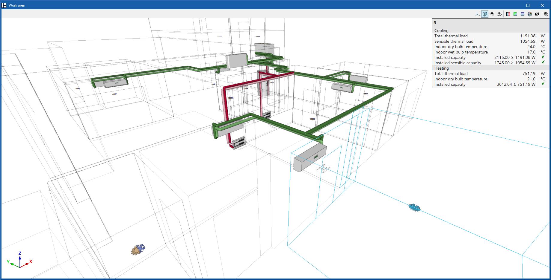
Manually assigning heat loads
If necessary, a percentage of the thermal loads of the spaces (either loads read from the BIM model or loads entered directly into the program) can also be manually assigned to the desired equipment using the "Assign" icon in the "Thermal loads" group in the upper toolbar or by editing each element and using the options in the "Assigned thermal loads" section.
This option is useful if the terminal elements in each space are not entered, e.g. if in a ducted fan coil or air conditioning system the air distribution system is not modelled.
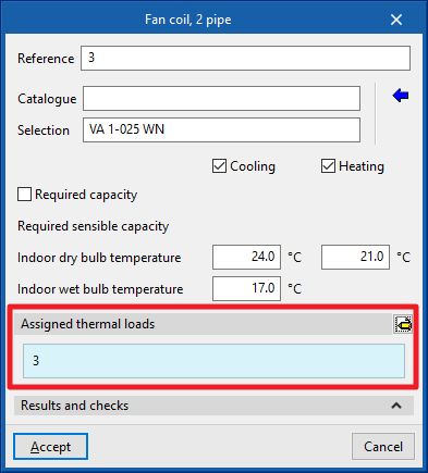
Required capacity
If the "Required capacity" option in the equipment editing panel is activated, the power required to be covered by the equipment is defined directly. This power requirement can be entered in such a way that it is equivalent to the thermal load of the space and can be different from the nominal power of the equipment.
If the "Power requirement" option is deactivated, the system is sized at rated power.
This affects the flow rate of the water pipes leading to the equipment, and also affects the requirements of the generating equipment, such as heat pumps or boilers.
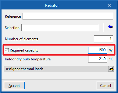
Calculations, checks and designs
In the "Calculation" group of the main toolbar, under the "Installation" tab, there are options for calculating, checking and designing the elements of the model:

Update results
Checks whether the parameters that have been entered to analyse the system are within the allowed ranges.
The result is a direct display with error or warning messages on the elements that present a problem in the check, in addition to the results and reports available after the analysis in the "Results and checks" section of the edit panel of each element.
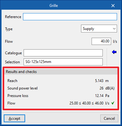
Design
Designs the system, i.e. it automatically selects the size of the elements.
The design algorithm of the terminal elements keeps the selection made by the user if all the checks carried out on the equipment are fulfilled.
In the editing panel of some elements, the program also allows the partial design with the corresponding tool in the lower right-hand area.
For previously defined fittings, these fittings are deleted during the design process (extending the ducts so that they are not disconnected) and are automatically generated again (positioning the fitting and adjusting the length of the ducts).
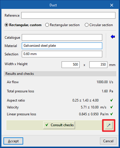
Thermal and acoustic analysis in ducts
The program can carry out the thermal and/or acoustic analysis of air duct networks. To do this, follow the steps below.
Activation of thermal and acoustic analysis in ducts
Thermal and/or acoustic analyses are activated in the "General options" of the "Project" group, in "Air distribution".
In this window, you can activate the boxes "Calculate heat loss from ducts" and/or "Calculate the airborne noise transmission through the duct system".
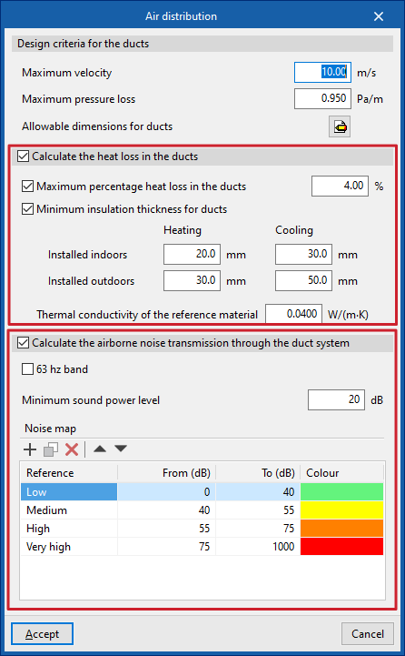
Entering data for equipment or starting points in the duct installation
Data for equipment or starting points in the duct system can be entered in the following ways to perform thermal and/or acoustic analyses.
Entering acoustic data for generic equipment
Acoustic data is entered into generic equipment by accessing its editing panel in the "Generic elements library" and then clicking on the option available next to the "Acoustic data" label (or "Acoustic data (supply)" and "Acoustic data (Return/Extraction)" in equipment with two associated networks).
This option is available for ventilation and air conditioning equipment with air distribution, such as fan coils with duct distribution, air conditioners, fans and heat recovery units.
The "Sound power level" of the equipment can be "Manual" or "Calculated":
- If "Manual" is selected, the "Sound power level (dB)" must be defined for each of the following frequencies: 63, 125, 250, 500, 1000, 2000 and 4000 hertz.
- If "Calculated" is selected, the "Adaptation coefficients" for these same frequencies are defined using the wizard on the right, which allows the necessary values to be imported by selecting the "Fan type" from "Centrifugal" or "Axial".
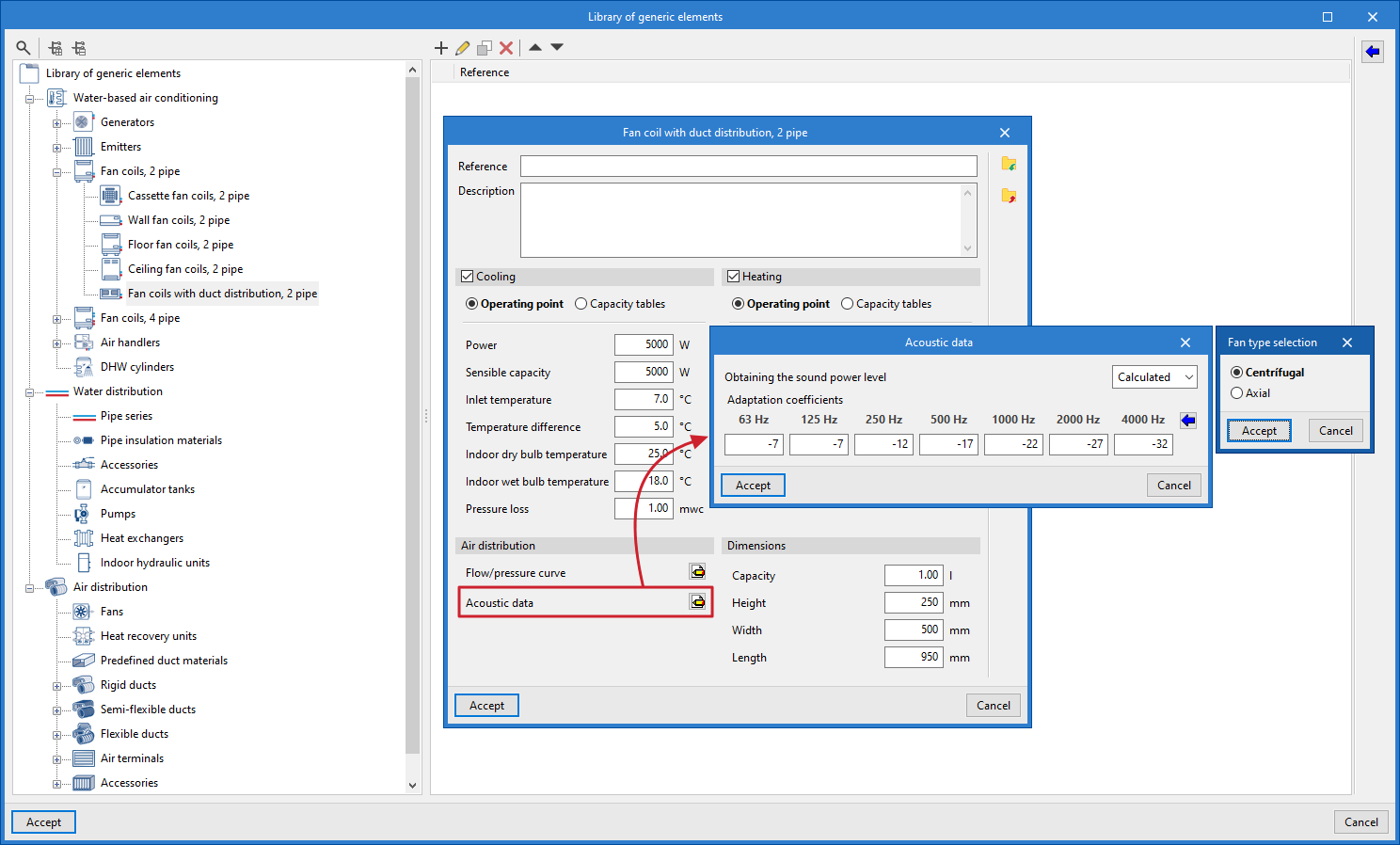
Entering thermal and acoustic data at the starting points of duct pre-installations
In the case of duct pre-installations without equipment installed, the "Heat loss" and "Acoustic attenuation" boxes are activated in the "Starting point of the duct pre-installation" editing window.
When the "Heat loss" option is activated, the "Thermal power" and "Air inlet temperature" are defined for "Heating" and/or "Cooling".
When the "Sound attenuation" option is activated, the "Sound power level" is defined in the same way as explained for generic library equipment.
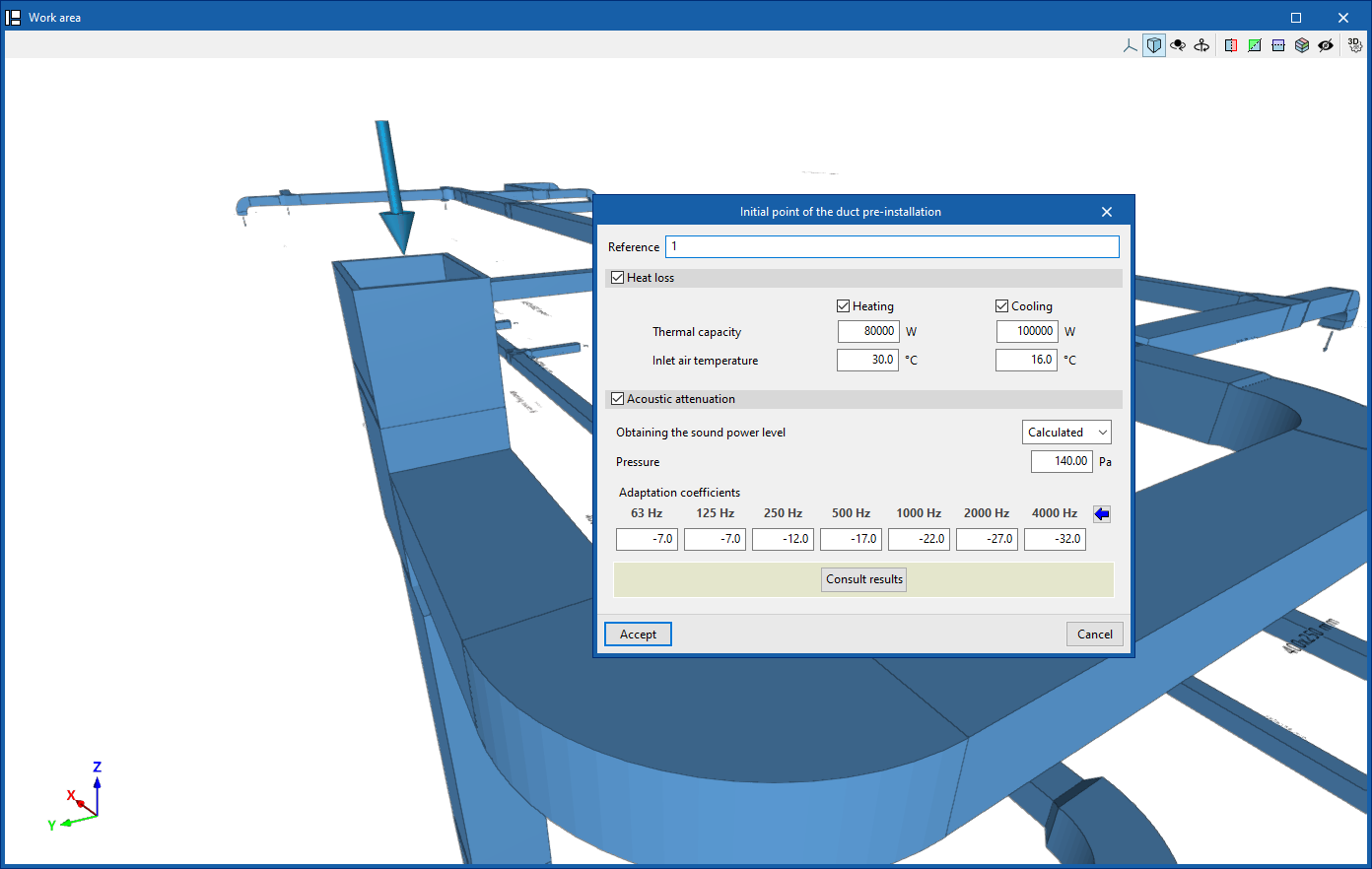
Entering acoustic data in manufacturer equipment
Acoustic data is included alongside other technical characteristics in the equipment listed in the manufacturer catalogues of the Open BIM Database. Therefore, simply download and update the catalogue and select the desired equipment to load this data.
Consulting thermal and acoustic analysis results
If the options indicated above have been selected, the thermal and/or acoustic analysis in ducts is performed in a combined manner when the model analysis is launched, using the options in the "Analysis" group. The results obtained can then be consulted in the following ways.
Consulting results for specific elements
The program allows you to consult the lists of acoustic analysis results from the editing panel for each piece of equipment or section of duct, in the "Acoustic analysis" section, by clicking on "Check results".
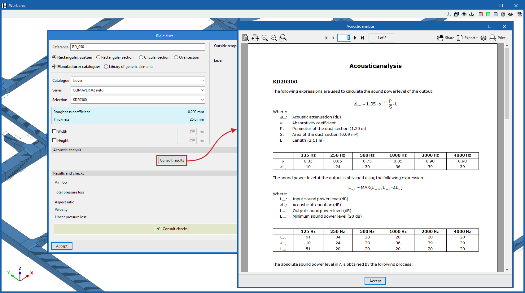
Graphical analysis of thermal and acoustic analysis results
Displays the results graphically by colouring the duct sections in the model using the "Graphical analysis of results" option, selecting the "Heat loss (Heating)", "Heat loss (Cooling)" or "Acoustics" options in its settings.
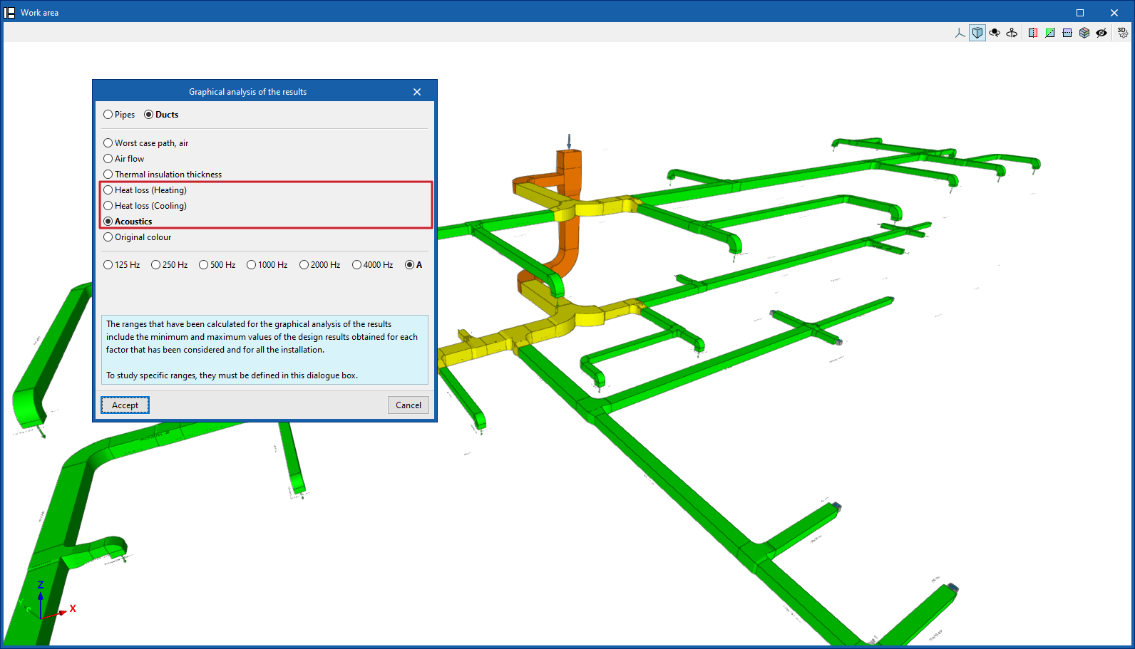
"Heat loss" and "Acoustics" lists
Finally, the program offers the "Heat loss" and "Acoustics" reports from the "Documents" option in the "Results" group.
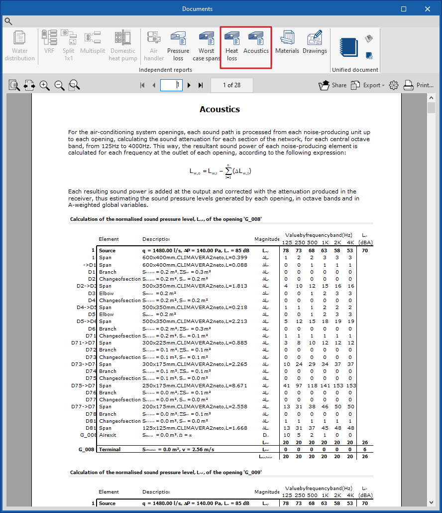
Results output
In the "Results" group of the main toolbar, under the "Installation" tab, there are options for obtaining information on the analysis results of the installation:

Analysis results can also be obtained in the following ways:
Checking the results on screen
After the analysis, CYPEHVAC displays the results in the tooltip or information text that appears when the cursor is positioned on an element in the system, and the compliance of the checks carried out on it. To do this, the "Show information texts" option in the top right-hand toolbar must be checked.
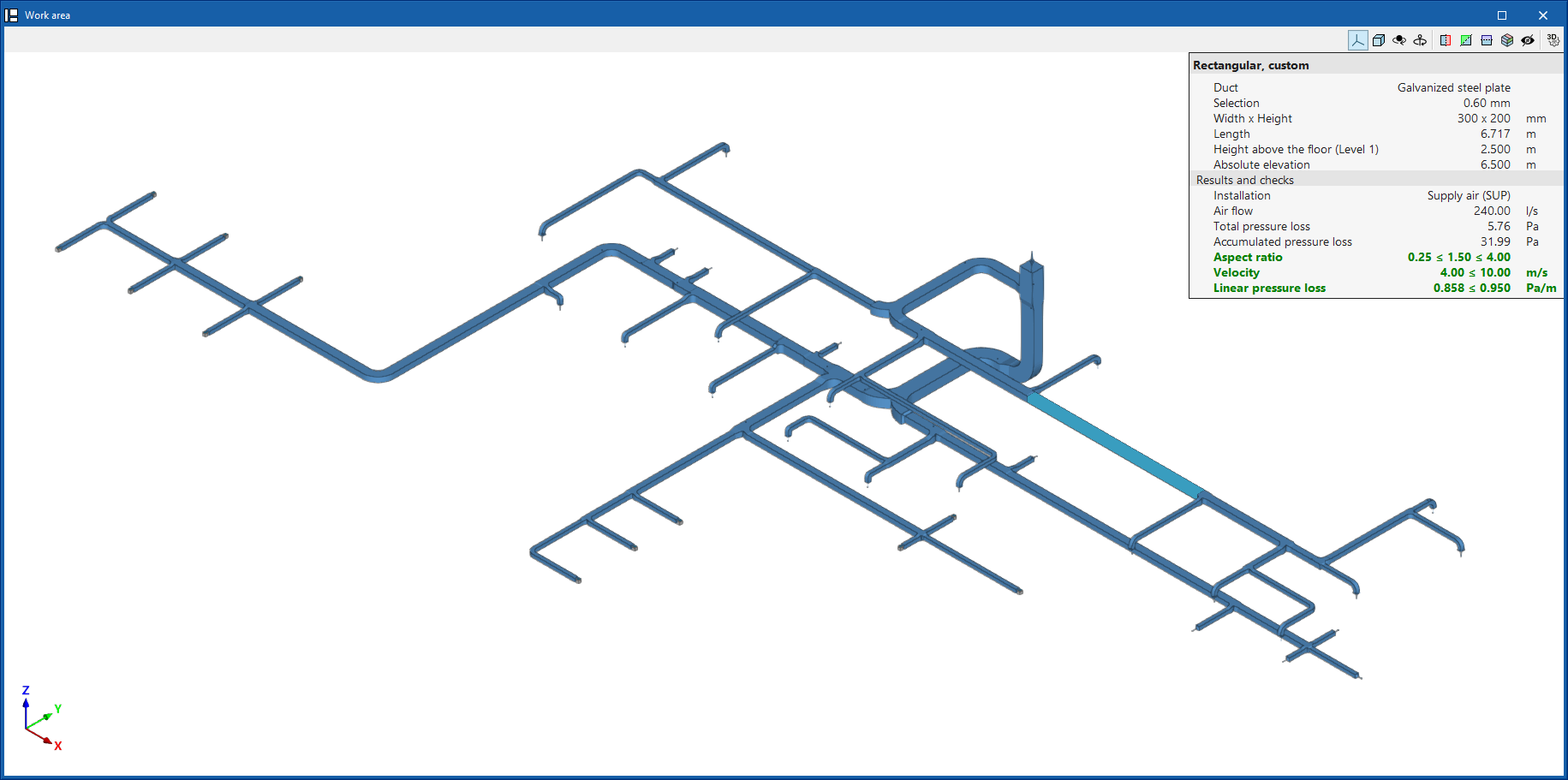
Results and checks
The program also displays the "Results and checks" of the last analysis carried out in the corresponding section of the edit panel of each element, as well as its compliance status.
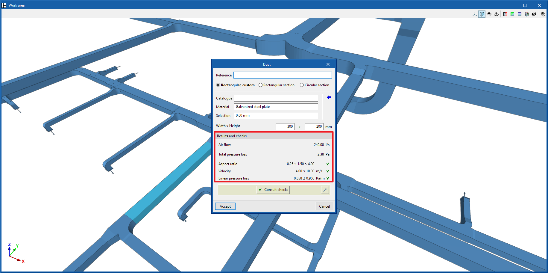
Check reports by element
By editing some elements, the specific check report can be consulted through the corresponding option.
These reports detail the analysis expressions and references used, as well as the analysed quantities and value limits.
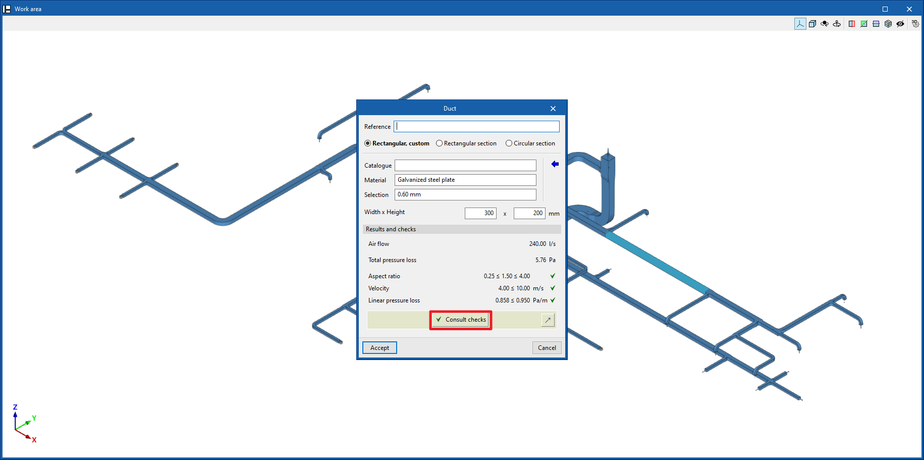
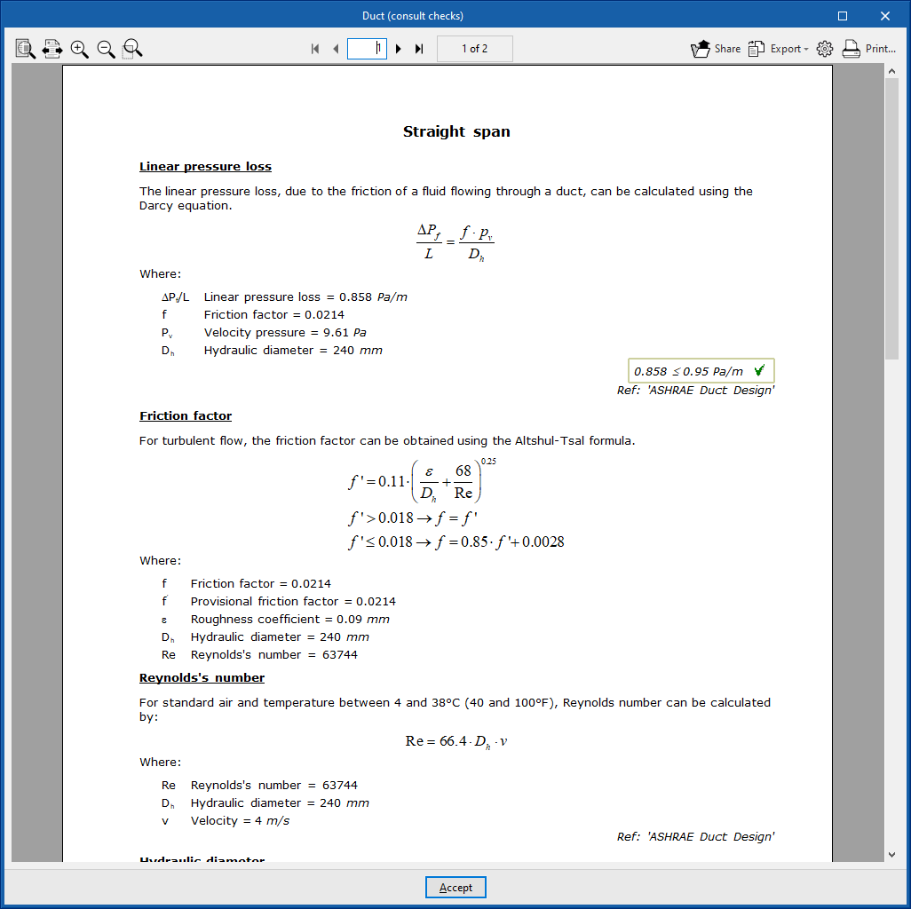
Graphical analysis of results
By means of the "Graphical analysis of results" option in the "Results" group of the main toolbar, the analysed values of different magnitudes are displayed by colouring the sections of the water distribution system.
By default, the program displays the minimum and maximum values of each factor obtained in the analysis for the entire system. However, the colour scale can be adjusted according to the specific ranges of minimum and maximum values defined in the corresponding dialogue box.
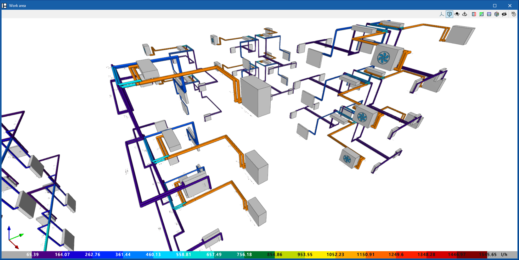
The results available in the graphical analysis of results are as follows:
- Worst case path, cold water
- Worst case path, hot water
- Flow
- Pressure loss of the span
- Velocity
- Thermal insulation thickness
- Linear heat flow
- Hot water temperature
- Cold water temperature
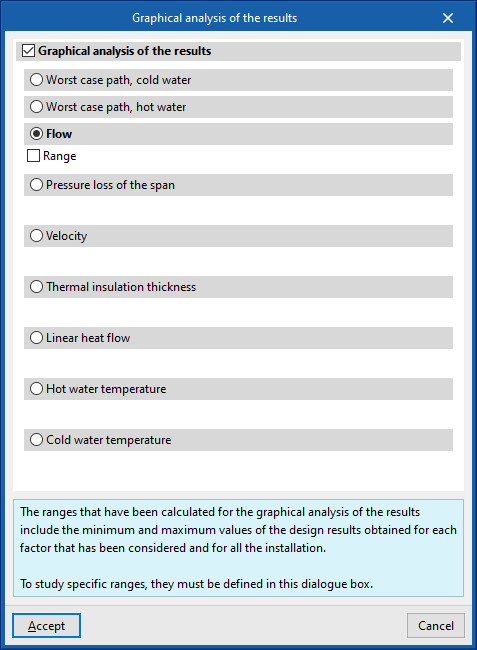
Show/Hide incidents
If this option is activated, the elements in which an error has occurred are highlighted. By positioning the cursor on these elements, the message describing the error can be displayed.
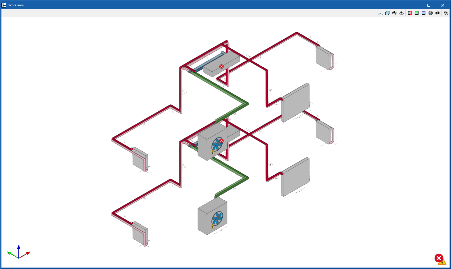
Job reports
The program can print the reports directly or generate HTML, PDF, TXT, RTF or DOCX files.
Reports are obtained via the "Reports" option in the "Results" group of the main toolbar.
- Water distribution
Displays a report with the analysis results of the water distribution system. The data for the following elements are included:- Generators
- Emitters
- Fittings
- Distribution
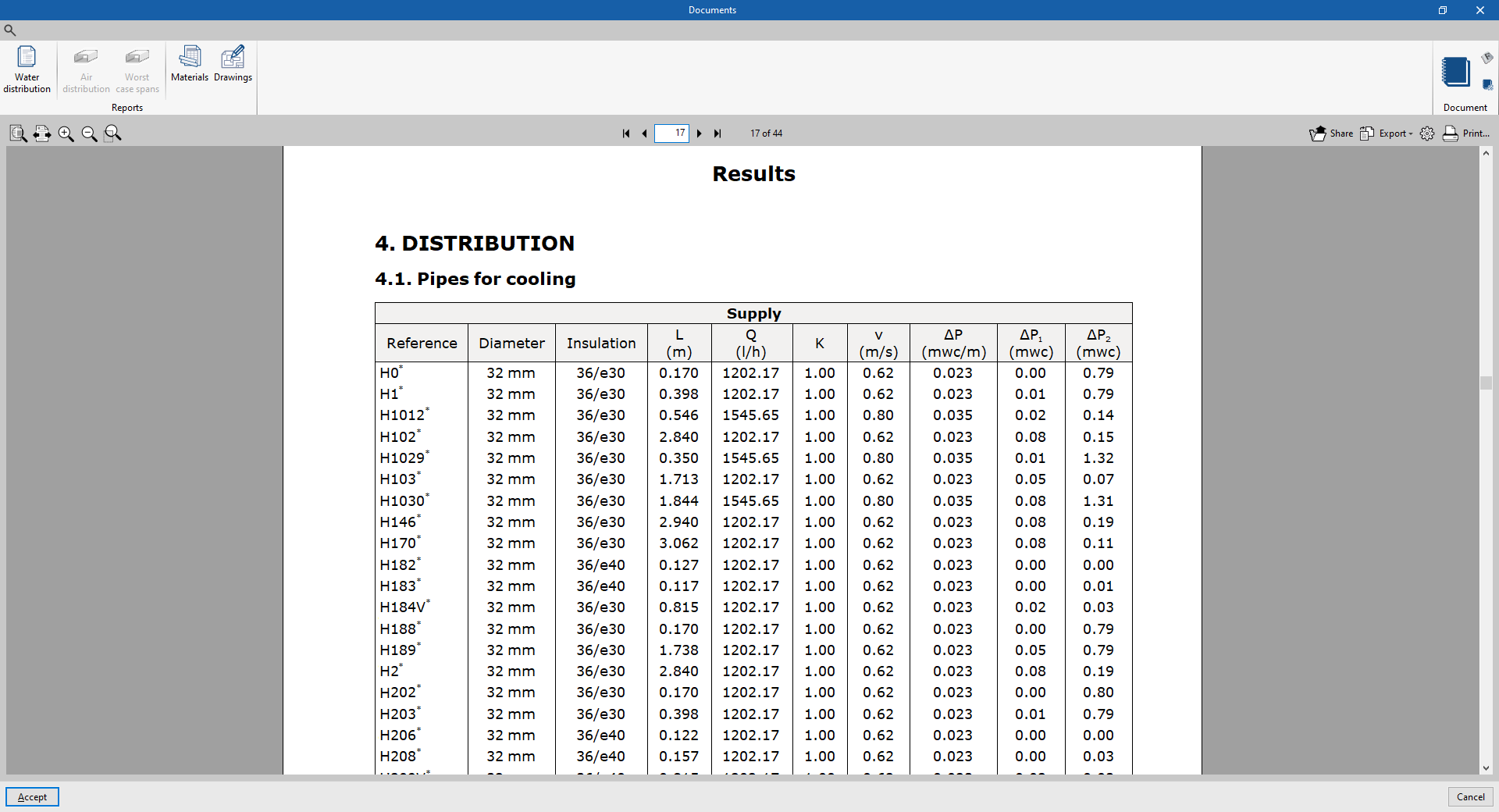
- System-specific reports
Each of these reports shows specific information on the following systems entered in the model:- VRF
- Split 1x1
- Multisplit
- Air-source heat pump
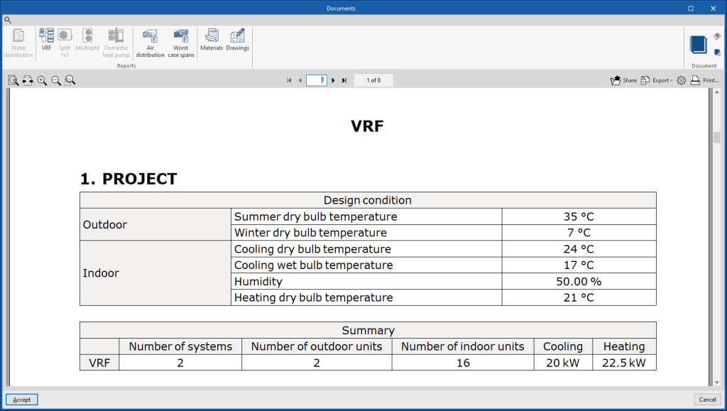
- Air distribution
Displays a report with the analysis results of the air distribution system. The data for all ducts and nodes are organised by air duct sections in a table including the following information:- Reference
- Type
- Flow
- Diameter equivalent
- Dimensions (Width, Height)
- Velocity
- Length
- Linear pressure loss
- Total pressure loss
- Accumulated pressure loss
- Material
- Most unfavourable sections
Displays a specific report of the most unfavourable air duct runs for each independent tree in the system.
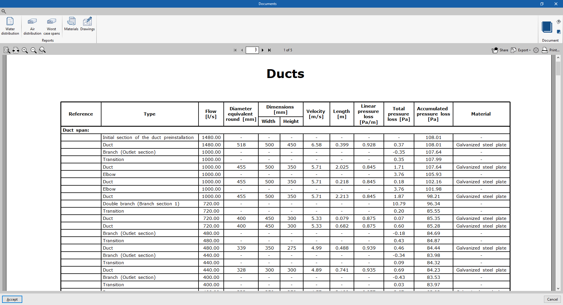
- Materials
Displays the table of materials with the measurement of the elements arranged in the system.
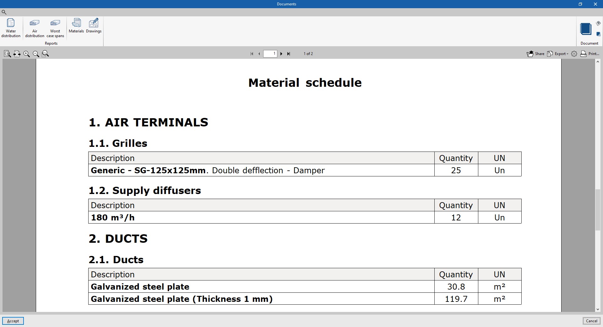
- Drawings
With this option, the program can print drawings as reports, so they can be integrated and exported as another document.
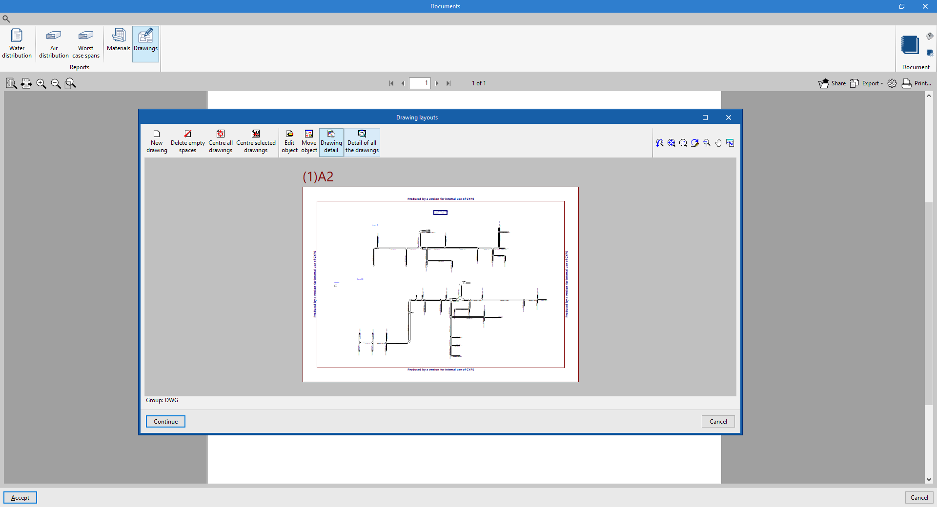
Document configuration
To create documents that incorporate the information of several selected reports together, the "Document configuration" option is used. It allows the following data to be configured:
- Title
- Description
- Page header (optional)
- Project; Location; Developer; Author; Date
- Reports to be included
The document created is printed using the "Document" option.
The "Document styles" can also be modified using the corresponding option.
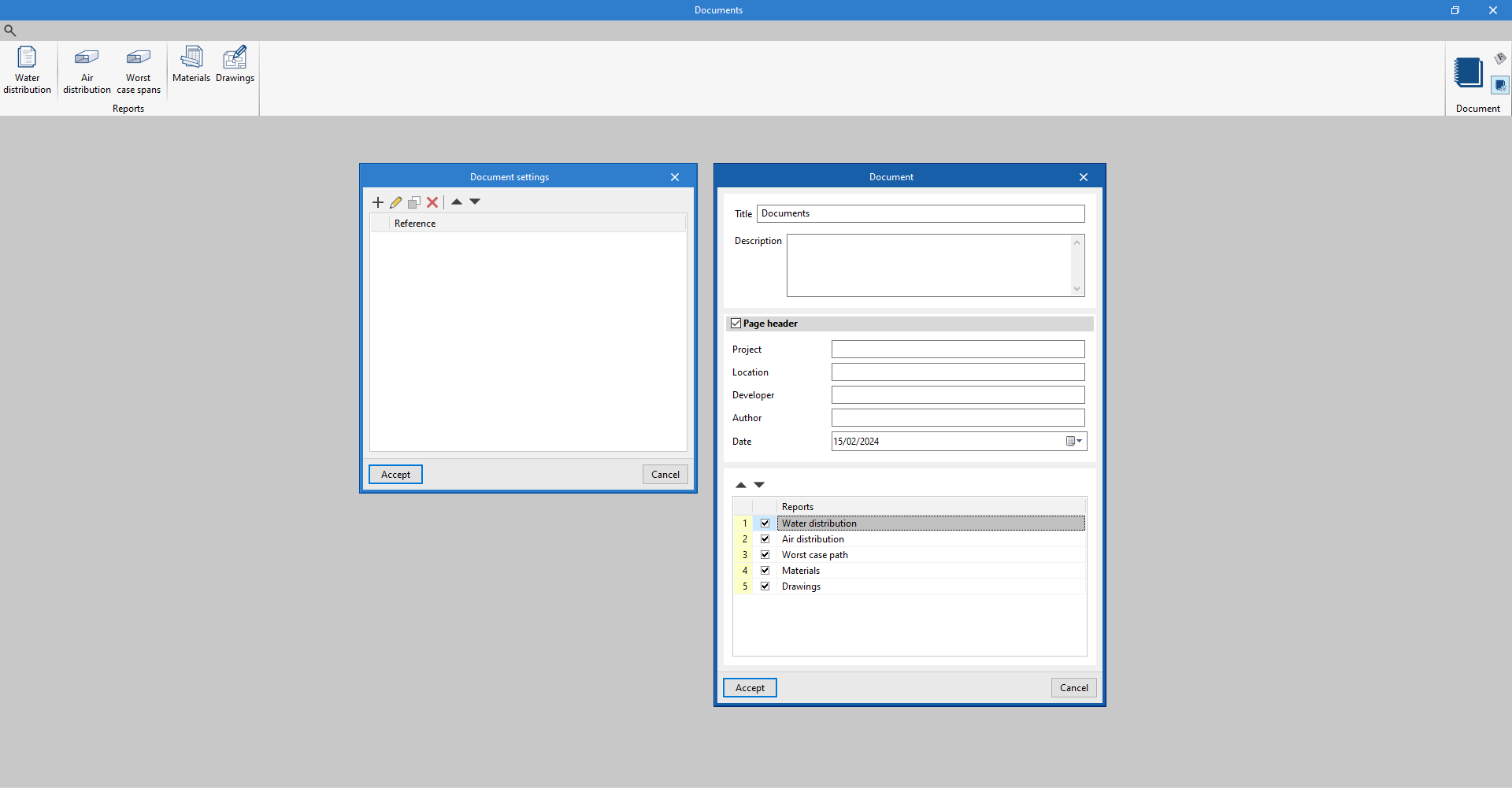
System diagram
By using the "Diagram" option in the "Results" group of the main toolbar, the program generates and displays the diagram of the direct expansion systems.
These diagrams can be incorporated into the job drawings.
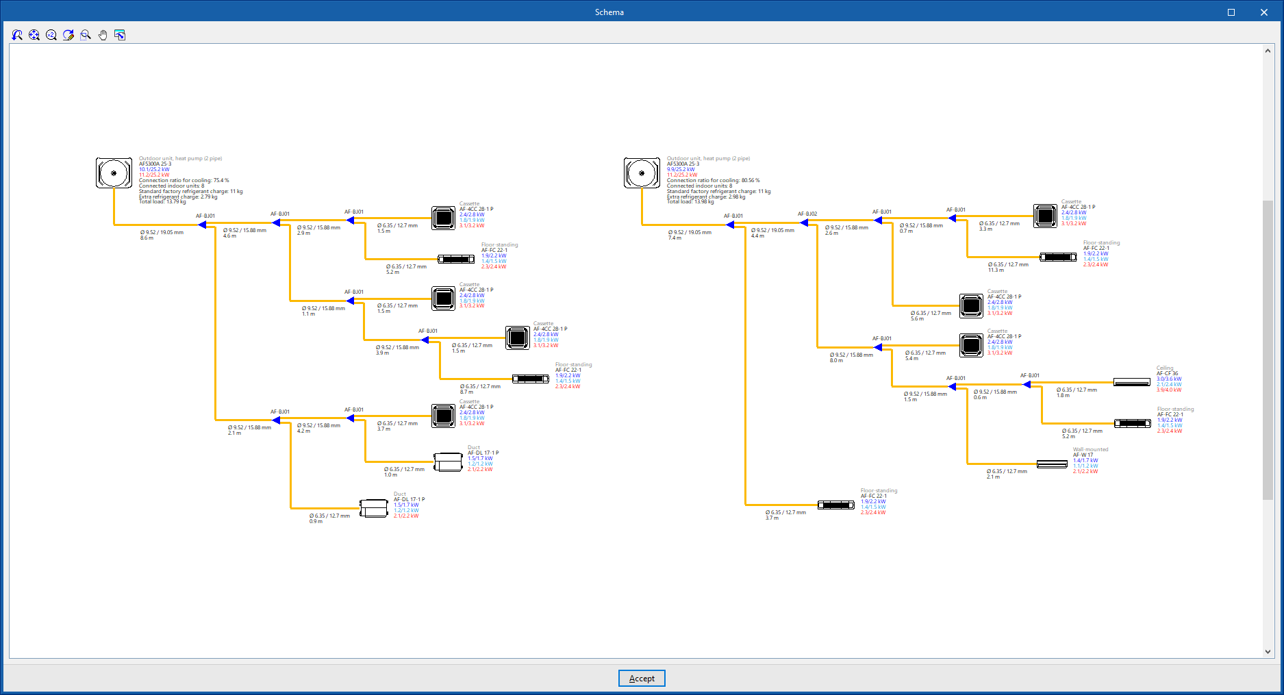
Control diagram of the system
By using the "Control diagram" option in the "Results" group of the main toolbar, the program generates and displays the control diagram of the VRF systems.
The control diagram can also be incorporated into the job drawings.
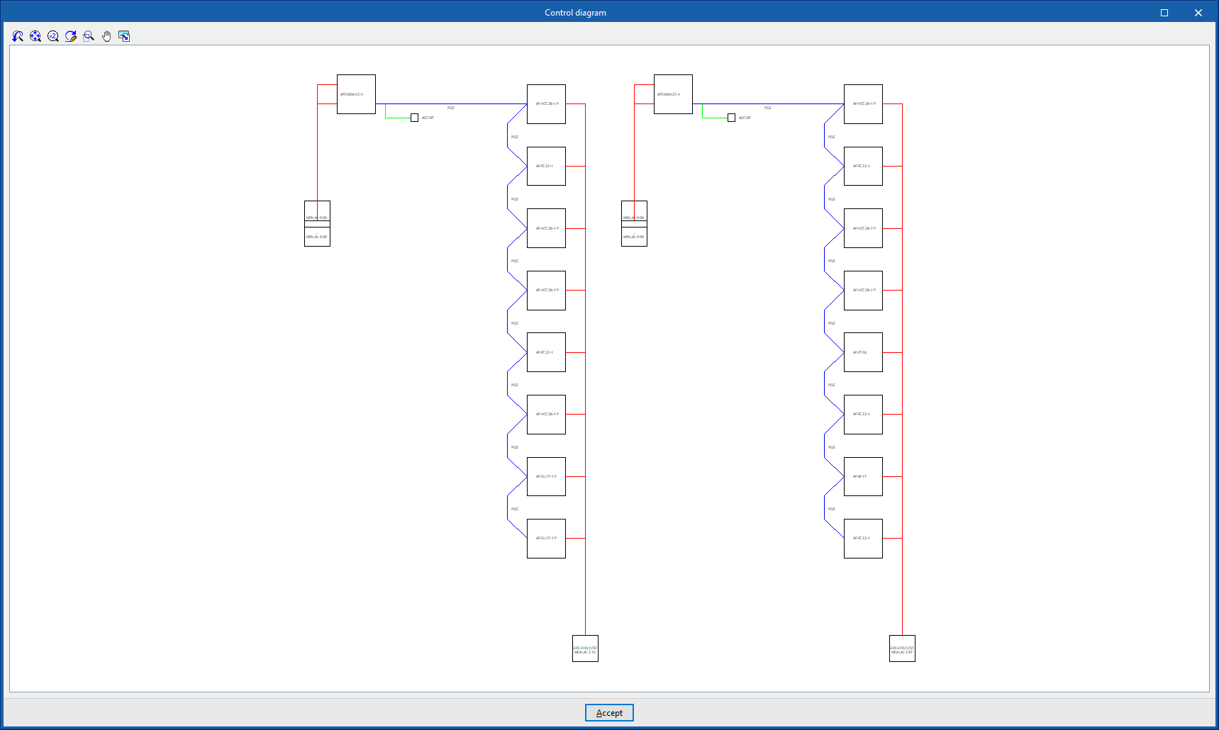
Drawings in DWG, DXF or PDF format
The program can print the drawings of the job on any graphic peripheral configured on the computer, or create DWG, DXF or PDF files.
The following options can be configured when editing drawings:
- Views to be drawn
- Options
- Generate vector images
- Draw the DXF/DWG template
- Include .glTF files in the drawings
- Scale
- Details
The drawings can be obtained via the "Drawings" option at the top of the interface or via the "Reports" option in the "Results" group of the main toolbar.
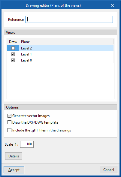
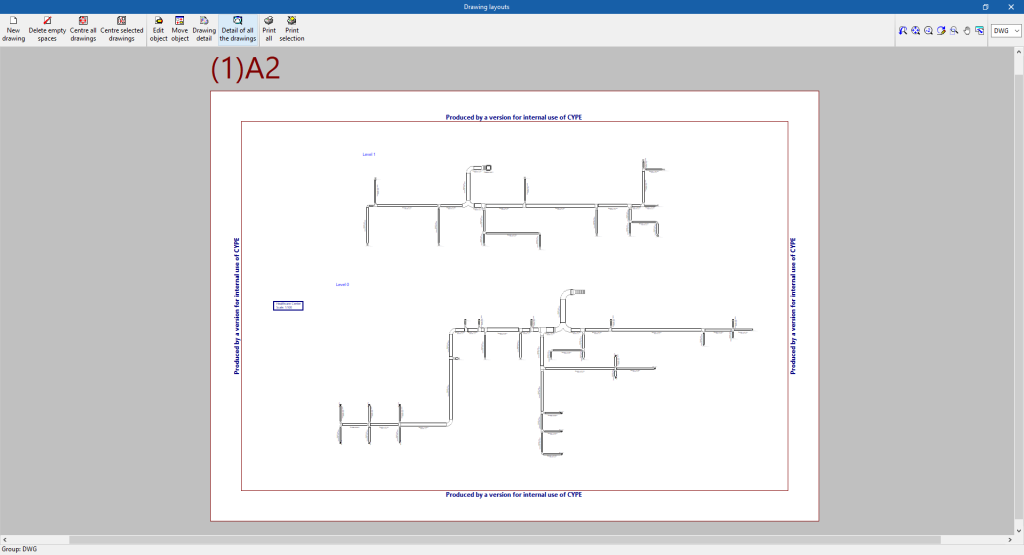
Results in the "Bill of quantities" tab
If the work is carried out in the "Bill of quantities" tab, CYPEHVAC will provide the following documents:
- Exporting the bill of quantities in FIEBDC-3 format (BC3)
- Bill of quantities reports (in HTML, PDF, TXT, RTF or DOCX format)
GLTF file compatible with BIMserver.center
When a project is exported to the BIMserver.center platform, a 3D model is automatically exported in GLTF format for the integration of the system model in the Open BIM project, so that it can be visualised:
- on the online platform;
- in the BIMserver.center app for iOS and Android;
- in virtual reality and augmented reality;
- in other CYPE programs.
Integration into the BIMserver.center platform
Many of CYPE's programs are connected to the BIMserver.center platform and allow collaborative work to be carried out via the exchange of files in formats based on open standards.
Please note that, to work on BIMserver.center, users can register on the platform free of charge and create a profile.
When accessing a program connected to the platform, the program connects to a project in BIMserver.center. This way, the files of the projects that have been developed collaboratively in BIMserver.center are kept up to date.

| More information: |
|---|
| For further details related to using CYPE software via the BIMserver.center platform, please click on this link. |
Options available in CYPEHVAC
In the "BIMserver.center" group of the main toolbar, under the "Installation" tab, there are the features needed to use CYPEHVAC together with other BIMserver.center tools:

Update
Update information contained in models previously imported into the project, or import new models if desired.
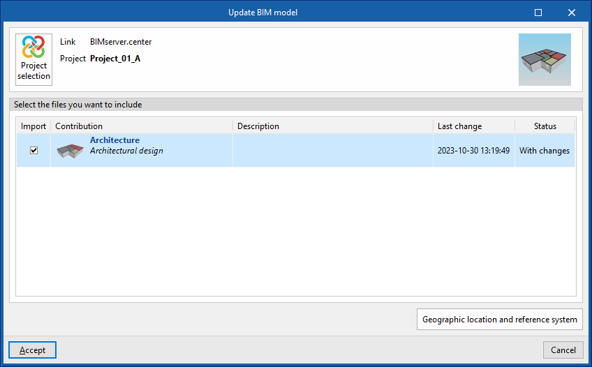
Share
Exports the information of the system developed with CYPEHVAC to BIMserver.center to share it with other users, including the quantities and analysis reports of the system.
During the export process, you can define information related to the identification of the files to be exported and the types of files that are generated:
- Name
- Description
- Additional files
- Reports (optional)
- DXF/DWG drawings (optional)
- Do not include the joints and transitions of the distribution systems (optional)
If this option is ticked, information relating to joints and transitions in the distribution systems will not be exported. This option should be enabled if you wish to subsequently use the Open BIM - Revit Plugin to generate the ducts as native Revit elements, as the joints and transitions are created within Revit itself.