Configuring general project data
In the "General data" menu at the top, you will find the "Edit general data of the job" option, which allows you to enter general information about the installation, such as materials and ground conditions, the parameters, limits and coefficients used in the analysis, and excavation data.

The options available are as follows:
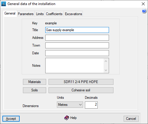
"General" tab
This allows you to enter the following general details, which will appear in the calculation lists, within the installation description:
- Key
Title of the project. To change it, use the "File" > "Save as" option. - Title
- Address
- Town
- Date
- Notes
In addition, the following options are available:
- Materials
Allows you to manage materials. - Soils
Allows you to manage soils. - Settings
You can configure the "Units" and the number of "Decimals" used.
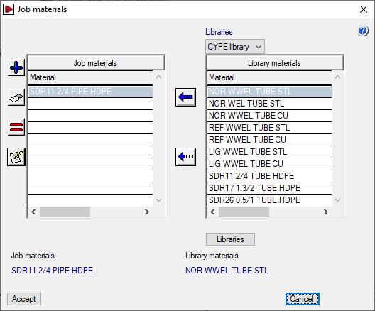
Materials management
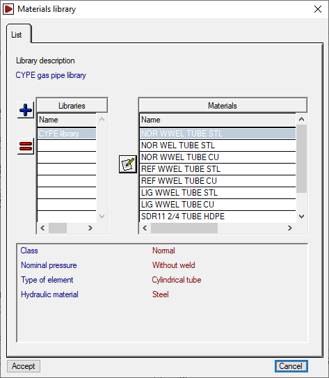
By clicking on the "Materials" button, you can manage the materials used in the site’s pipework, as well as the available material libraries. The window that appears displays two lists:
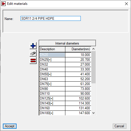
- The list on the left shows the "Project materials". You can create a material manually using the tools on the left, or import it from the library materials. When adding or editing a project material, you must specify the "Name" and the associated "Internal diameters".
- The list on the right shows the "Library materials". At the top, you can select the library you wish to view. The program includes a default library. You can view the internal data for each library by clicking on the "Libraries" button at the bottom; there, you can define the "Library description", and its "Abbreviation", and for each item included, the "Name" and the associated range of "Internal diameters" are displayed.
The first button between the two lists allows you to create a site material by importing information from one of the materials available in the library. The second button allows you to add the grades of the selected library material (on the right) to the selected site material (on the left).
Soil management
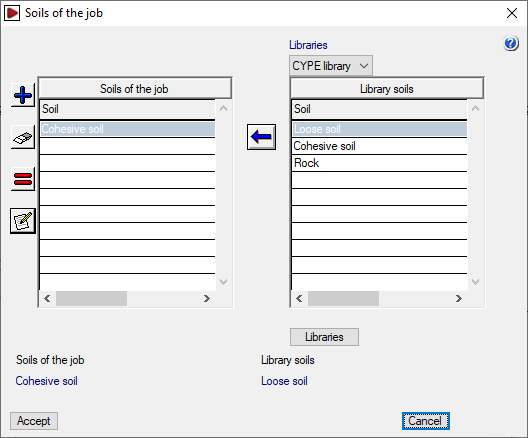
By clicking on the "Soils" button, you can manage the terrains for the project, as well as the available terrain libraries. The window that appears displays two lists:
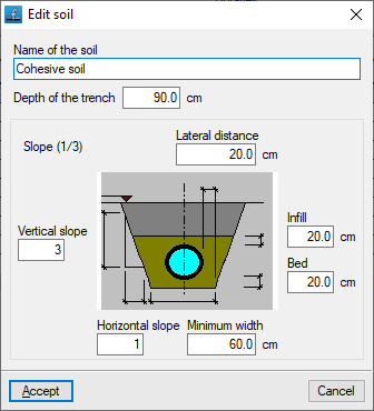
- The list on the left shows the "Soils of the job". You can create a terrain manually using the tools on the left, or import one from the library terrains. When adding or editing a site terrain, the "Name of the soil" and the following geometric parameters are specified: "Lateral distance", "Infill", "Bed", "Minimum width", and "Vertical slope" and "Horizontal slope" (which form the “Slope” ratio shown next to the graph).
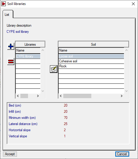
- The list on the right shows the "Library fields". At the top, you can select the library you wish to display. The program includes a default library. You can view the internal data for each library by clicking on the "Libraries" button at the bottom; there, you can define the "Library description", and its "Abbreviation", and for each plot included, the ‘Plot name’ and the aforementioned geometric parameters are displayed.
The first button between the two lists allows you to create a site plan by importing information from one of the site plans available in the library. The second button allows you to add the sections of the site plan selected from the library on the right to the site plan selected on the left.
To continue creating a new project, you must create at least one material and one soil
The materials and sites will be available when editing each section via "Sections", "Edit calculation data".
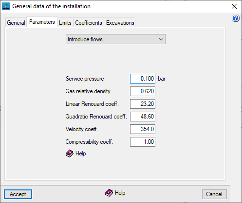
"Parameters" tab
This allows you to define the following parameters for the gas supply system:
- Data entry mode
This drop-down menu allows the user to select how consumption data will be requested.- Enter flow rates
Consumption loads shall be expressed in units of flow rate. - Enter power ratings
Power consumption loads shall be expressed in units of power. In this case, the following data for the fuel gas must be defined:- Higher heating value (GCV)
For natural gas, a GCV of 10,000 kcal/m³ may be assumed. At nodes where the heat input P is entered, the required flow rate Q is obtained by converting the heat input using the GCV, via the expression Q = P / GCV. - Lower heating value (LHV)
For natural gas, the LHV is usually around 90% of the gross heating value (GHV).
- Higher heating value (GCV)
- Enter flow rates
- Service pressure
- Gas relative density
The relative density of the fuel gas. In the case of natural gas, this ranges from 0.55 to 0.66, depending on its composition. - Linear Renouard coefficient The constant factor in the linear Renouard formula. It is the constant factor used in the linear Renouard formula for pressures below 100 mbar. A value of 23.2 is usually taken.
- Quadratic Renouard's coefficient
The constant coefficient in the quadratic Renouard formula. It is the constant factor used in the quadratic Renouard formula for pressures between 100 mbar and 16 bar. It is equal to 48.66 between 100 mbar and 4 bar, and equal to 51.5 between 4 and 16 bar. - Velocity coefficient: A constant in the gas velocity formula. It is usually taken to be between 354 and 378, depending on the pressure.
- Compressibility coefficient
The compressibility coefficient of the gas. It affects the calculation of velocity and takes the value 1 for pressures below 5 bar.
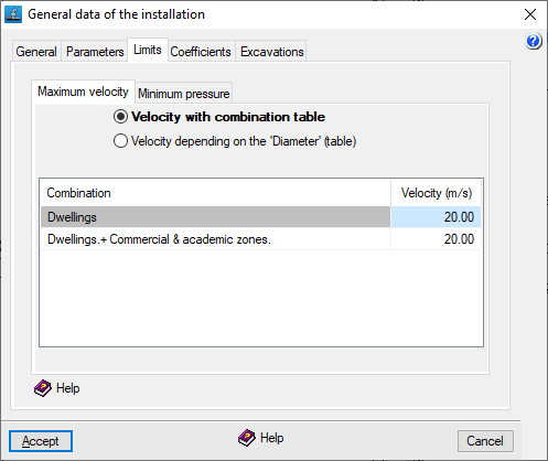
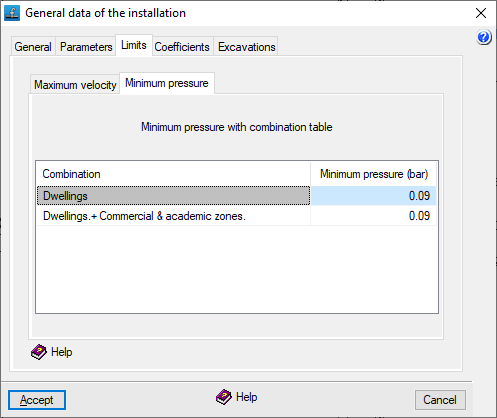
"Limits" tab
This tab is used to set speed and pressure limits within the system.
In the various tabs, you define the "Maximum velocity" in the gas conduits (which should not exceed 20 m/s, as the Renouard formula is no longer valid above this velocity) and the "Minimum pressure" at the nodes.
This can be done:
- Via the combination table (for "Maximum speed" and "Minimum pressure")
For each entry, the speed or pressure limit is defined for each combination specified under "General data", "Edit combinations". - Based on 'Diameter' (table) (for "Maximum speed")
Each entry defines the speed limit applied to pipes with diameters equal to or smaller than the specified value. For diameters larger than those specified, the limit for the largest diameter in the table applies.
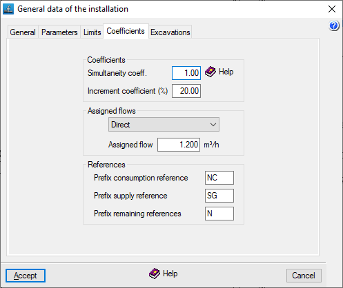
"Coefficients" tab
Coefficients
This tab is used to define two coefficients that are applied across the entire project:
- Simultaneity coefficient
This allows you to increase or decrease consumption levels. It is defined as a ratio of one and is applied to gas consumption across all combinations. This makes it possible to simulate operations at different times of the day or seasonal changes. By default, the value is set to one. - Increment coefficient (%)
This acts as an additional percentage applied to the effective length of the sections. This allows for the simulation of pressure drops caused by special components such as valves, bends or branches. The default value is set to 20%.
Assigned flows
This allows you to specify whether the loads on consumption nodes are defined by default directly or via allocation.
- Direct
Consumption will be entered directly in units of flow rate or power. - By rating
Consumption will be calculated based on a flow rate or power rating (corresponding to the value entered in the "Rating" field) and the corresponding number of units.
The load values and their definition type can be edited later in the edit panel for each node.
References
This allows you to set the prefixes that are automatically added to the references of installation nodes when they are added to the workspace, whether they are consumption nodes, general supply nodes or other nodes:
- Prefix: consumption reference
- Prefix: supply reference
- Prefix: remaining references
References can be edited later in the edit panel for each node.
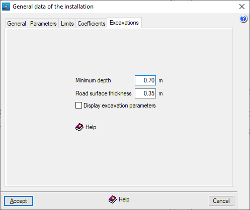
"Excavations" tab
This tab is used to define the following parameters relating to the site's excavations:
- Minimum depth
Allows you to set an alarm that alerts you when any point in the installation falls below this value (in the "Calculation results" report that appears after using the options in the "Calculation" menu). The minimum depth is measured from the ground level to the top edge of the inner face of the duct. - Road surface thickness:
This indicates the default distance between the road surface and the modified ground level. By default, this value is subtracted from the road surface elevation (entered in the "Edit node" panel) to obtain the ground level without the need to enter it manually. Furthermore, if the ground level is changed in that panel, a warning will be displayed if the specified pavement thickness is not met. - Display excavation parameters (optional)
The program allows you to calculate the excavation volumes for the project if at least one site has been defined and elevations and depths have been specified at the nodes. If you do not wish to enter this information or do not want to calculate the excavation, you can disable this option: in this case, the nodes will not require the entry of elevation values.
| Note: |
|---|
| Where there are multiple pavement thicknesses in the project, if the "Road surface thickness" value is changed in this section, any new nodes added from this point onwards will be calculated using the new thickness, but the previous thickness will be retained for nodes added earlier. |