Options in the "View" menu
The following options can be accessed from the "View" menu at the top of the interface.

Display options
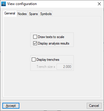
This allows you to control how the diagram elements are displayed on screen. The available options are as follows:
- "General" tab
- Draw texts to scale (optional)
- Display analysis results (optional)
- Display trenches (optional)
- Trench size x (value)
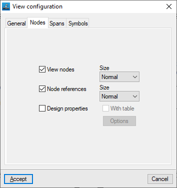
- "Nodes" tab
- View nodes (optional)
- Node references (optional)
- Design properties
- Options: Data to view at nodes
- With table (optional)
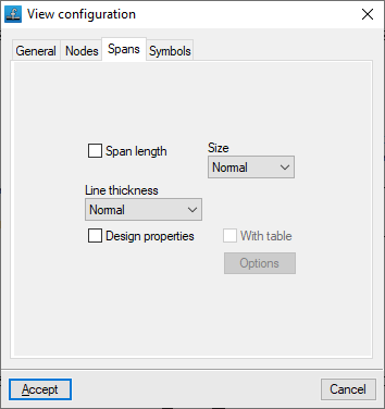
- "Spans" tab
- Span length (optional)
- Line thickness
- Design properties (optional)
- Options: Data to view at spans
- With table (optional)
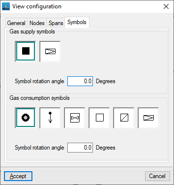
- "Symbols" tab
- Gas supply symbols
- Symbol rotation angle
- Gas consumption symbols
- Symbol rotation angle
- Gas supply symbols
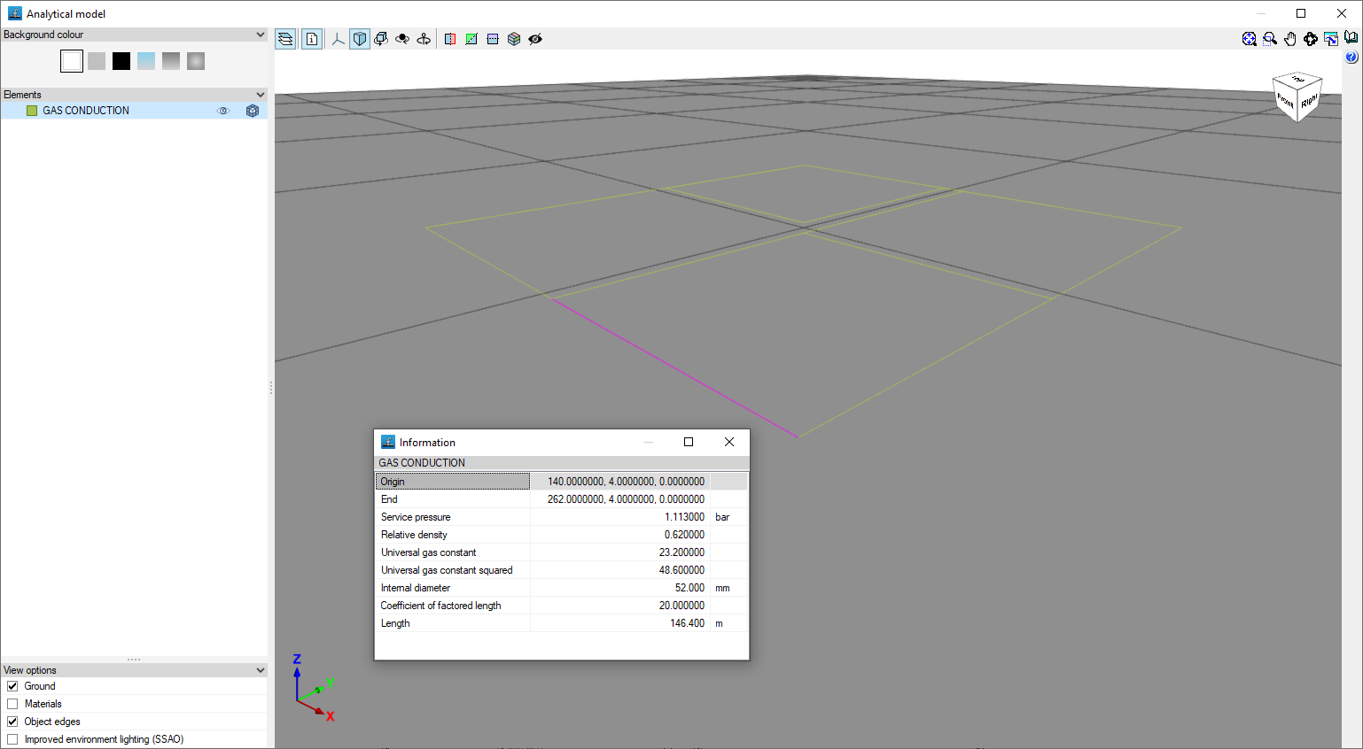
3D view
Once the installation has been analysed, this option allows you to open a window displaying a 3D view of the installation. You can also check the geometric characteristics of each section by selecting the "Information" option and clicking on the section.
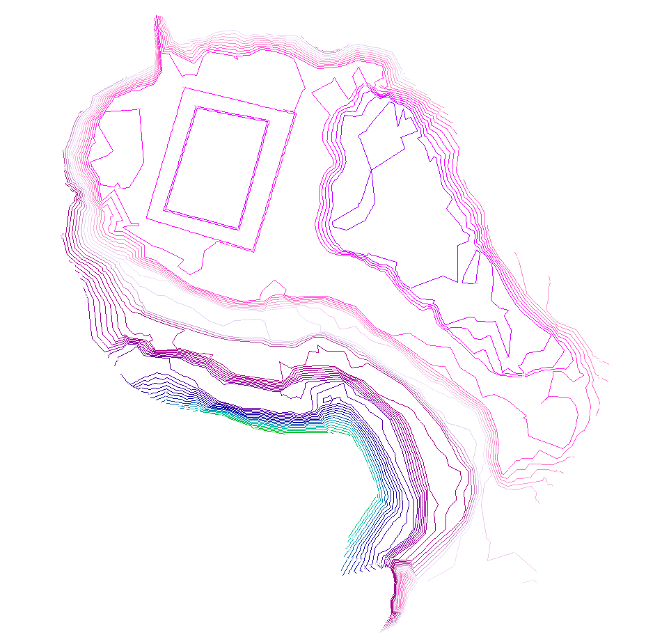
Show/hide the contour lines
This allows you to show or hide the contour lines generated on screen if you have imported an IFC file containing the terrain model during the project creation process.
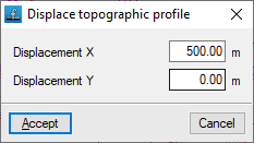
Displacing the topographic profile
This allows you to reposition the generated topographic profile if you have imported an IFC file containing the terrain model during the project creation process.