
Results output
Viewing results on screen
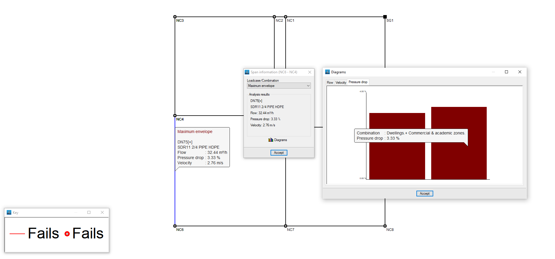
After the analysis, the program displays the results on the screen when selecting an element of the installation via the "Nodes" option, "Information", or via "Sections", "Information".
This includes the analysis data of the nodes and the analysis data of the sections, with results by laodcases, combinations or envelopes.
Reports
The program can be used to print the reports directly or to generate HTML, PDF, TXT, RTF or DOCX files.
The reports are obtained via the "Reports" option in the "File" menu or from the right-hand side of the top toolbar.
The following reports are available:
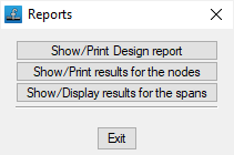
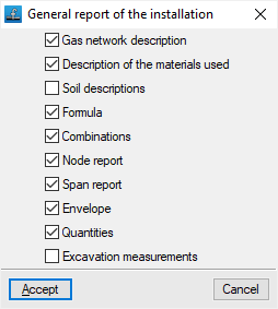
- Calculation report
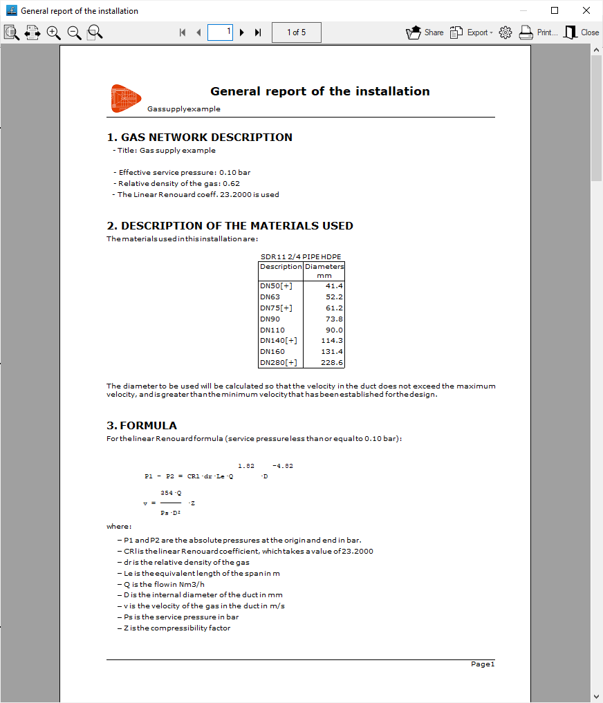
Prints the general report of the installation. It includes the following sections, which can be activated or deactivated:- Gas network description (optional)
- Description of the materials used (optional)
- Soil descriptions (optional)
- Formula (optional)
- Combinations (optional)
- Node report (optional)
- Span report (optional)
- Envelope (optional)
- Quantities (optional)
- Excavation measurements (optional)
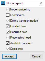
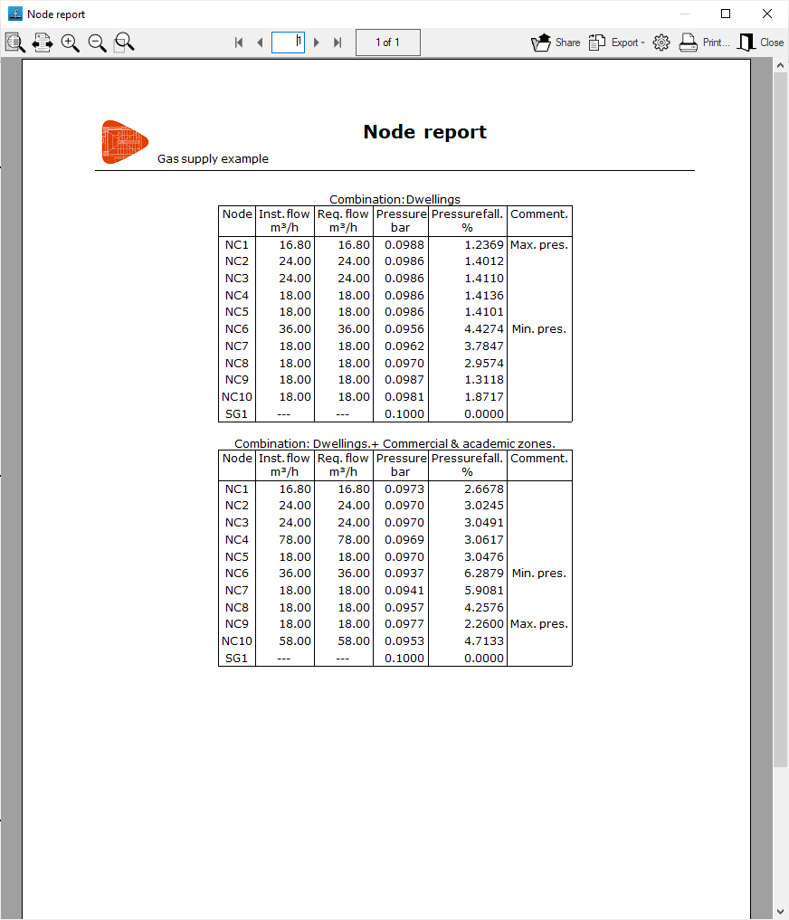
- Node report
Prints the report of the results in the nodes. It includes the following information, which can be activated or deactivated:- Node numbering (optional)
- Coordinates (optional)
- Delete transition nodes (optional)
- Installed flow (optional)
- Required flow (optional)
- Piezometric head (optional)
- Available pressure (optional)
- Comments (optional)
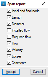
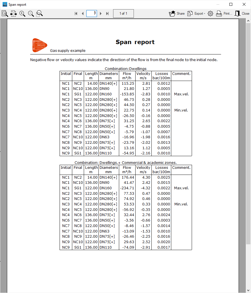
- Span report
Prints the report of the results in the spans. It includes the following information, which can be activated or deactivated:- Initial and final node (optional)
- Length (optional)
- Diameter (optional)
- Installed flow (optional)
- Required flow (optional)
- Flow (optional)
- Velocity (optional)
- Losses (optional)
- Comments (optional)
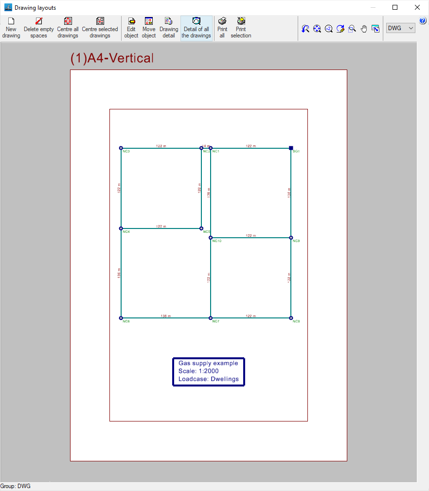
Drawings
The program can print the drawings of the job on any graphic peripheral configured on the computer, or create DWG, DXF or PDF files.
The drawings are obtained from the "Drawings" option in the "File" menu or from the right-hand side of the top toolbar.
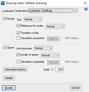
Editing the drawing offers the following options:
- Loadcase/Combination
Selects the loadcase, combination, envelope or oscillation for which data is to be displayed in the drawing. - Nodes (optional)
Displays the input information and analysis results of the nodes:- Size
- Node references (optional)
- Transition nodes (optional)
- Calculation properties (optional)
- Options: Flow (Power), Supply pressure, Elevation, Ground level elevation, Elevation fill, Pressure of the node
- Spans (optional)
Displays the input information and analysis results of the spans:- Line thickness
- Length of spans (optional)
- Calculation properties (optional)
- Options: Dimension, Material, Flow, Pressure drop, Velocity
- Information tables
- General information table (optional)
- Quantities information table (optional)
- Excavation information table (optional)
- Scale
- Details
GLTF file format compatible with BIMserver.center
If the job has been linked to a BIMserver.center project, a 3D model is generated in GLTF format to integrate the system model into the project when it is exported to the platform, allowing it to be visualised:
- on the online platform;
- on the BIMserver.center app for iOS and Android;
- on virtual reality and augmented reality;
- on other CYPE programs.