General job data settings
The "General data" menu at the top of the page contains the "Edit general data of the job" option, which allows users to enter general data of the installation, such as materials and soils, parameters, limits and coefficients used in the analysis or excavation data.

The following options are available:
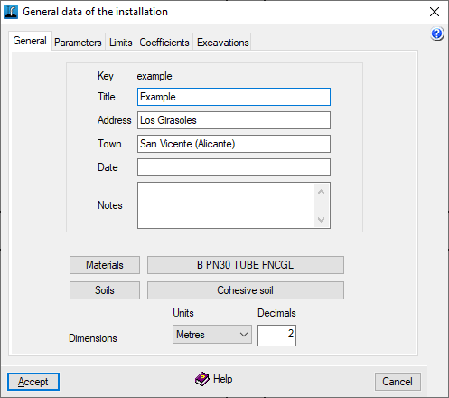
"General" tab
The following general data can be entered, which will appear in the analysis reports, within the description of the installation:
- Key
Name of the job. To modify it, go to "File", "Save as". - Title
- Address
- Town
- Date
- Notes
In addition, the following options are available:
- Materials
Accesses the management of materials. - Soils
Accesses the soil management. - Dimensions
Sets the units and the number of decimals used.
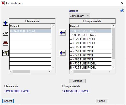
Materials management
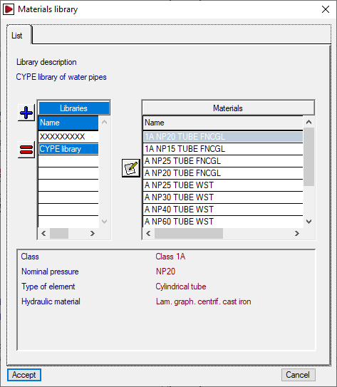
By clicking on the "Materials" option, users can manage the materials of the pipelines of the job, as well as the available material libraries. Two lists are displayed in the window that appears:
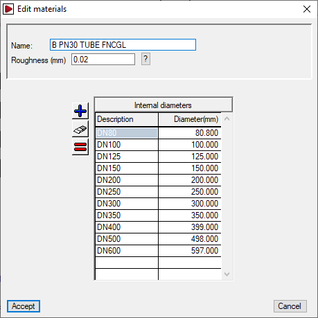
- The report on the left represents the "Job materials". It is possible to create a material manually using the tools on the left, or to import it from the library materials. When adding or editing a material from the job, the name, roughness and associated bore series are indicated in the corresponding sections.
- The report on the right shows the "Library materials". The library to be displayed is selected at the top. The program incorporates a default library. The internal data of each library can be consulted by clicking on the "Libraries" button at the bottom; there the "Library description" and its "Abbreviation" are defined, and for each material included, the "Name" and "Roughness" are shown, as well as the series of associated "Internal diameters".
The first button between the two lists is used to create a job material by importing the information from one of the materials available in the library. The second button is used to add the series of the library material selected on the right to the job material selected on the left.
Soils management
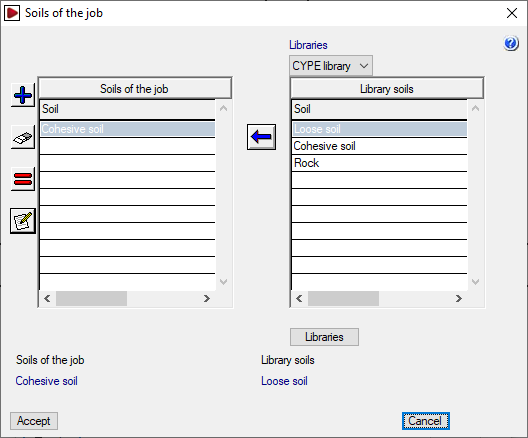
By clicking on the "Soils" button, the soil of the job, as well as the available soil libraries, can be managed. Two lists are displayed in the window that appears
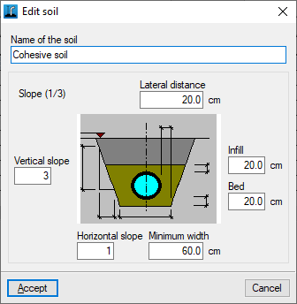
- The list on the left shows the "Soils of the job". Soils can be created manually with the tools on the left, or imported from the soils library. When adding or editing soils of the job, the "Name of the soil" and the following geometric parameters are indicated: "Side distance", "Fill", "Bed", "Minimum width", and "Vertical slope" and "Horizontal slope" (which form the "Slope" relationship shown next to the graph).
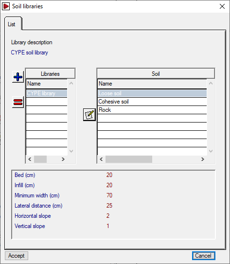
- The list on the right shows the "Library soils". At the top, you select the library you want to display. The program incorporates a default library. It is possible to consult the internal data of each library by clicking on the "Libraries" option at the bottom; there the "Library description" and its "Abbreviation" are defined, and for each soil included, the "Soil name" and the geometric parameters mentioned are displayed.
The first button between the two lists is used to create a soil for the job, importing the information from one of the available soils in the library. The second button adds the series from the soils in the library selected on the right to the soil of the job selected on the left.
To continue creating a new job, at least one material and one soil must be created.
The materials and soils will be available when editing each section from "Spans", "Edit analysis data".
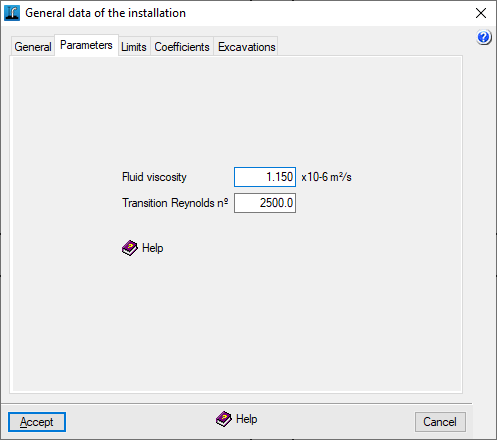
"Parameters" tab
The following hydraulic parameters can be defined. These values must not be changed except in exceptional cases and with full knowledge of their implications.
- Fluid viscosity
Kinematic viscosity of the fluid; by default, the value 1.15 x 10⁻⁶ m2/s is displayed (1 m2/s=10000 Stokes). - Transition Reynolds nº
Transition Reynolds number between laminar and turbulent regime. This value is taken as the boundary for the application of the formulation and is usually set between 2000 and 4000. By default, the value 2500 is shown.
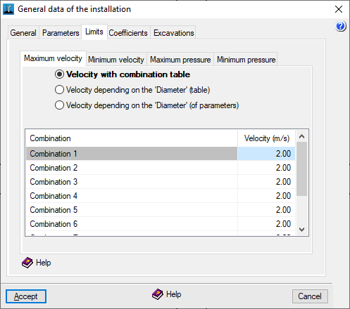
"Limits" tab
These limits are set for velocities and pressures in the installation. These limits act in two ways:
- If the "Analysis" option of the "Analysis" menu is used, a warning is displayed on the elements of the installation that do not reach the minimum values or that exceed the maximum values;
- If the "Design" option of the "Analysis" menu is used, in the case of speeds, the program restricts the operation of the installation to the values between the minimum and maximum values defined, whenever possible, as design limits; and in the case of pressures, they act as range limitations in the pressure of the nodes, so that the program looks for the solution that allows the greatest number of nodes in that range.
The different tabs define the "Maximum speed" and "Minimum speed" in the sections, and the "Maximum pressure" and "Minimum pressure" in the nodes.
This can be done:
- By combination table
- Each entry defines the velocity or pressure limit for each combination defined in "General data", "Edit combinations".
- Depending on 'Diameter' (table) (for "Maximum velocity" and for "Minimum velocity")
- Each entry defines the velocity limit applied to pipes with diameters equal to or smaller than the indicated diameter. For larger diameters than those indicated, the limit of the largest diameter in the table is applied.
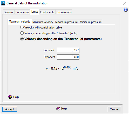
- As a function of 'Diameter' (parametric) (for "Maximum velocity")
- Expresses the velocity v as a function of the diameter D by defining the constant C and the exponent E, such that v = C - DE (m/s).
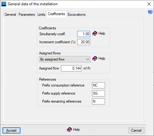
"Coefficients" tab
Coefficients
Two coefficients can be defined which are applied in the analysis in a general way to the whole job:
- Simultaneity coefficient
Increases or reduces consumption. It is defined on a per unit basis and applies to water consumption in all combinations. This makes it possible to simulate operation at different times of the day or seasonal changes. By default, a value equal to unity is set. - Length increment coefficient (%)
This acts as an additional percentage of the resistant length of the sections. This enables the simulation of head losses due to special elements such as valves, elbows or branches. By default, a value of 20 % is set.
Assigned flows
Defines whether the consumption node loads are defined by default directly or assigned.
- Direct
Consumption shall be entered directly in flow rate units. - By assigned flow
Consumption shall be entered based on a flow rate value per allocation (corresponding to the value indicated in the "Allocation" field) and the corresponding number of units.
The values of the loads and their type of definition can be edited later in the editing panel of each node.
References
Establishes the prefixes that automatically make up the references of the installation's nodes when they are entered in the work area, whether they are consumption nodes, general supply nodes or the rest of the nodes:
- Prefix consumption reference
- Prefix supply reference
- Prefix remaining references
The references can be edited later in the editing panel of each node.
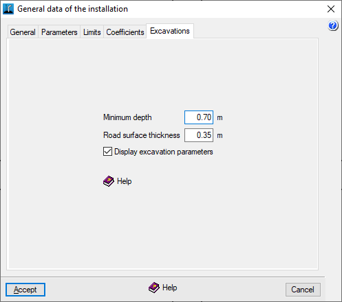
"Excavations" tab
Defines the following parameters related to the excavations of the installation:
- Minimum depth
Sets an alarm to warn when any point of the installation falls below this value (in the "Analysis results" report that appears after using the "Analysis" menu options). The minimum depth is measured from the level to the upper edge of the inside face of the conduit. - Road surface depth
Indicates the default distance between the grade and the modified terrain. This value is subtracted by default from the grade elevation (entered in the "Edit node" panel) to obtain the terrain elevation without having to type it in. Additionally, if the terrain elevation is changed in this panel, a warning will be given if the established road surface thickness is not complied with. - Display excavation parameters (optional)
The program can calculate the excavation volumes of the installation if at least one terrain has been defined and the dimensions and depths of the nodes have been provided. If this information is not required or if there is no need to calculate the excavation, it is possible to deactivate this option: this way, the nodes will only require the entry of the value of the "Elevation".
| Note: |
|---|
| When there are several road thicknesses in the job, if the value of the "Road surface thickness" is changed in this section, new nodes entered from this point onwards will be designed with the new thickness, but for the previously entered nodes the old thickness will be retained. |