Inserting and editing nodes
The "Nodes" menu at the top of the program interface contains the following options for adding and editing installation nodes.
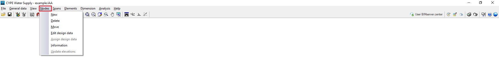
New
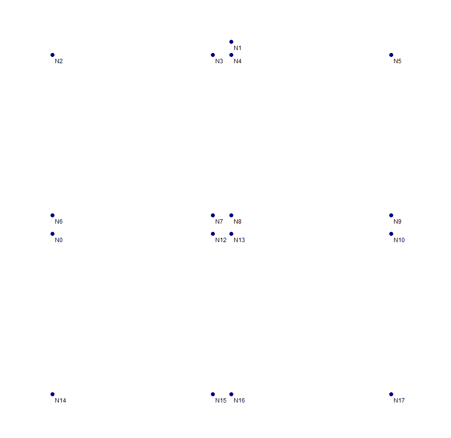
Used to insert nodes in the workspace.
Nodes are created by default as transition nodes, i.e. nodes with no consumption that allow changes in direction whilst maintaining the continuity of the section in the design. They can subsequently be edited via "Nodes", "Edit design data". If you right-click when inserting a new node, you can also access the design data editing panel for the node being inserted.
There are several ways to position nodes in the model when using this option:
- By absolute coordinates
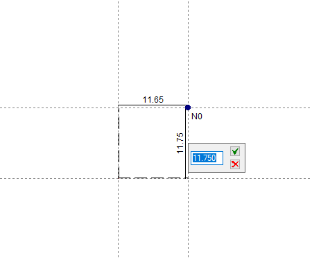
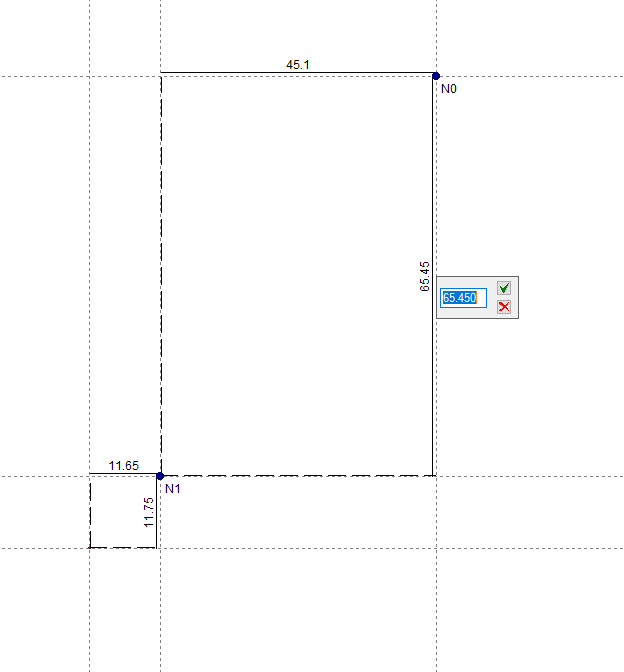
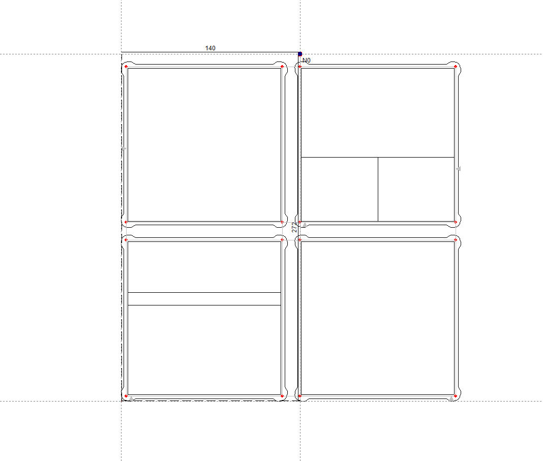
When entering the first node or base node of the installation by left-clicking on the screen, enter the node’s absolute X-coordinate and press the “Enter” key; then enter the absolute Y-coordinate and press the “Enter” key again. - By relative coordinates
Starting from the entry of a base node, the remaining nodes can be entered using relative coordinates, i.e. by specifying distances relative to other nodes. To do this, left-click on the screen where you wish to enter the node and enter the relative X and Y coordinates relative to the position of the next node. - By capturing from DXF or DWG
The options for importing DXF or DWG files are valid for entering nodes and sections. - Automatic generation of geometry
From the "File" menu, click on “Import” and select "Geometry" to automatically generate the installation geometry from a DXF or DWG file. This file must use the metre as its drawing unit, and the grid must be close to the coordinate origin. In this option, only the layers containing the sections you wish to use for generation should be activated.
Delete
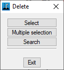
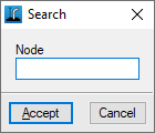
Deletes the selected node. You can use the left mouse button to draw a rectangular selection area on the screen to delete multiple nodes. Furthermore, clicking the right mouse button brings up options to "Select" a single node, perform a "Multiple selection" node by node, or "Search" for a node by its reference.
Move
This allows you to reposition the selected node. After clicking on the node, click on another point to specify the new position.
Edit analysis data
This allows you to edit the selected node. You can use the left mouse button to draw a rectangular selection area on the screen to edit multiple nodes, selecting the fields you wish to edit. Furthermore, clicking the right mouse button brings up options to "Select" a single node, perform a "Multiple selection" node by node, or "Search" for a node by its reference.
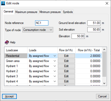
In the edit window that appears, enter the node data:
- "General" tab
- Node reference
- Type of node
- Consumption node
A node where the water consumption flow rate is defined for each loadcase. When this type of node is selected, the program displays a table at the bottom that allows you to define the flow rate for each loadcase. This table contains the following columns:- Loadcases
- Loads
Flow rate can be defined in two ways:- Direct
- By assigned flow
- Flow
The flow rate is defined by entering its value directly if the "Direct" option has been selected, or by entering a value per "Allocation" and the "Number of units" to be considered, if the "Per allocation" option has been selected. - Total flow
Displays the total flow value.
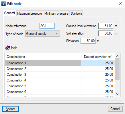
- General supply
Supply point for the installation. The program allows you to define a single supply or multiple supplies for the network. When you select this type of node, the program displays a table at the bottom that allows you to define the available pressure value for each combination in the "Tank level" column. In this way, you can simulate different supply conditions for the installation. - Transition node
A node with no consumption that allows changes of direction whilst maintaining the unit of the section in the design.
- Consumption node
- Ground level elevation
The level reached by the surface after the trenches have been backfilled and the road surface has been laid. - Soil elevation
The level of the modified ground (not the undisturbed ground) from which excavation begins. The difference between the finished ground level and the ground level must be greater than the value for "Sub-base thickness" defined in "General data", "Edit general project data". - Elevation
Dimension of the lower part of the inner surface of the pipe at the node. This is the dimension required for the hydraulic analysis of the pipes.
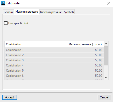
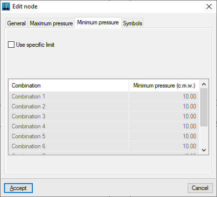
- "Maximum pressure" and "Minimum pressure" tabs
Enters specific pressure limits for the node being edited, for each of the load cases shown in the table.- Use specific limit (optional)
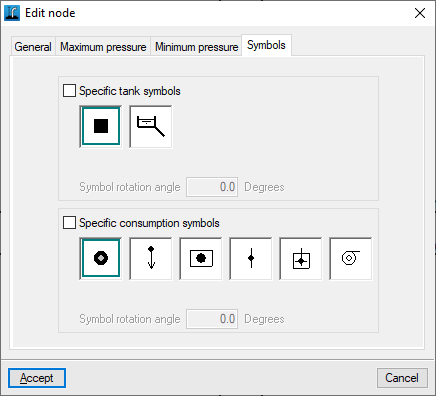
- "Symbols" tab
Defines specific symbols for the node currently being edited.- Specific tank symbols (optional)
- Specific consumption symbols (optional)
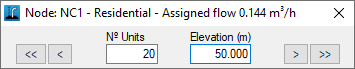
Assign analysis data
This allows you to assign data to nodes quickly.
When you click on the option, a small window opens in the top-left corner of the screen. At the same time, the node with the lowest reference number will be highlighted in yellow, and you can view and/or edit the node’s data (such as the number of units, flow rate and elevation). You can navigate through all the nodes using the corresponding buttons.
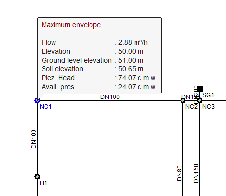
Information
This allows you to view the data entered in the node.
If the structure has been analysed, the analysis results for the node are also displayed for the combination currently selected. Furthermore, clicking on the node opens a window where you can view the results for any loadcase, combination, envelope and oscillation, both analytically and graphically: the "Graphs" button displays the "Piezometric head" and "Pressure" graphs for the different combinations.
Update dimensions
Update the elevations of all nodes based on the terrain topography defined in the BIM model.