Beam options in the "Project" menu
The "Beam options" in the "Project" menu, within the "Beam input" tab, allow you to adjust the settings for the following parameters related to the drawing and analysis of beam-type elements:
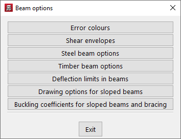
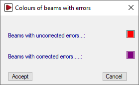
Colours of beams with errors
In this dialogue box, you can change the colour used to outline "Beams with uncorrected errors" and "Beams with corrected errors" on the screen.
| Note: |
|---|
| Beams with errors are those that show incidents marked as such (and not as warnings) from "Error assessment" in "Project > General data > By position > Beam options". |
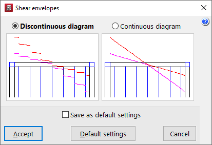
Shear envelopes
Allows you to adjust the representation of shear envelopes on beams. The layout can follow:
- a "discontinuous diagram", which takes into account the variation in shear stress along the beam (recommended in the case of columns supported on beams),
- or a "continuous diagram", in which case it is represented taking only the extreme values into account.
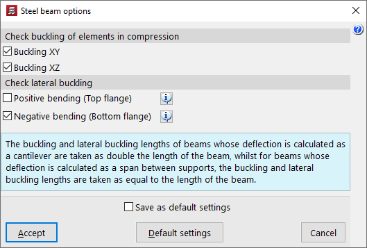
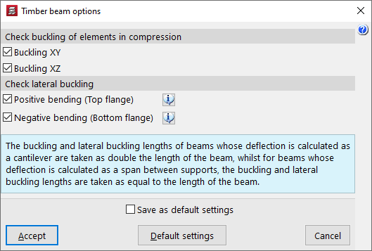
Options for steel beams / Options for timber beams
These options allow you to access two dialogue boxes where the following specific checks are activated for steel beams or timber beams.
In the "Check buckling of elements in compression" section, buckling checks are activated for both planes of metal or timber beams under compression by ticking the boxes "Buckling XY" and/or "Buckling XZ".
In the "Check lateral buckling" section, it is possible to activate the lateral buckling check for each of the wings of the steel beams, or the lateral overturning check for positive or negative bending of the timber beams:
- Positive bending (upper flange) (optional)
Activating this option will check the upper flange of beams that do not support slabs along their entire length for lateral buckling, such as cantilever beams, beams next to openings, or beams where the upper flange protrudes above the slab edge. - Positive bending (lower flange) (optional)
Activating this option will check the lateral buckling of the lower flange of beams that do not support slabs along their entire length, such as beams under slabs, cantilever beams, beams next to openings, or beams where the lower flange protrudes below the slab.
| Note: |
|---|
| In beams whose deflection is analysed as a cantilever, the buckling and lateral buckling lengths are considered to be equal to twice the length of the beam. On the other hand, in beams whose deflection is calculated as a span between supports, the buckling and lateral buckling lengths are taken to be equal to the length of the beam. |
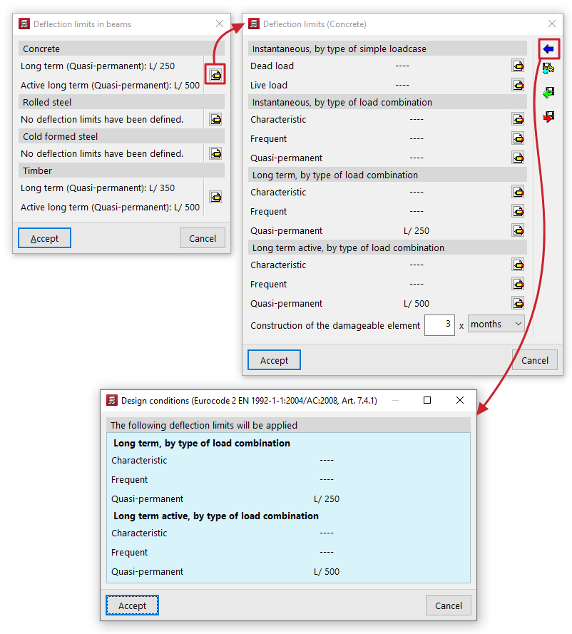
Deflection limits in beams
You can set the deflection limits for beams made of the different materials shown: "Concrete", "Rolled steel", "Cold formed steel" and "Timber".
By pressing the edit button on the right, you can configure the following deflection limits for each material:
- Instantaneous, by type of simple loadcase (Dead load, Live load)
- Snapshot, by type of load combination (Characteristic, Frequent, Quasi-permanent)
- Long term, by type of load combination (Characteristic / Frequent, Quasi-permanent) (for "Concrete" and "Timber")
- Long term active, by type of load combination (Characteristic, Frequent, Quasi-permanent)
In some cases, the wizard in the top right-hand corner allows you to import the deflection limit values from the "Design conditions" of the standards selected in the "General data".
The other options on the sidebar allow you to import and export the information on the configured deflection limits to .bibgen files saved on disk.
Beams that exceed these deflection limits will be marked with an error.
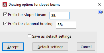
Drawing options for sloped beams
This option opens a dialogue box where you can activate and modify the prefixes used to label inclined beams and bracing diagonals:
- Prefijo de viga inclinada (opcional)
- Prefijo de diagonales de arriostramiento (opcional)
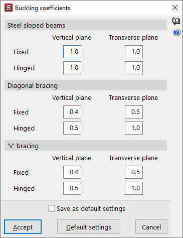
Buckling coefficients for steel sloped beams and bracing
Permite ajustar los coeficientes de pandeo en ambos planos ("Plano vertical" y "Plano transversal") de los siguientes elementos:
- Steel sloped beams
To obtain the buckling length of each sloped beam, the buckling coefficients entered here are considered to multiply the length between the extreme nodes of the beam, even in the case where two sloped beams entered by the user appear to intersect at a point, since the program does not generate such an intersection. - Diagonal bracing
To obtain the buckling length of each diagonal bracing, the buckling coefficients introduced here are considered to multiply the length between the extreme nodes of the diagonal, without taking into account the intermediate node that the program generates at the intersection of bars for this purpose. - 'V' bracing
The buckling coefficients of the "Vertical plane" and the "Transverse plane" are established, respectively, in a vertical plane containing the bar and the global Z-axis of the structure, and in the plane transverse to it, and not according to the local axes of the bar.
Different coefficients can be defined for both "Bi-potentiated" and "Bi-articulated" entities.