Consulting quantities, displacements and forces in flat and waffle slabs
To consult the quantities, displacements and forces at nodes of slabs and waffle slabs in CYPECAD, as well as the generated mesh and the deflection between two points, after calculating the project it is necessary to open the "Results" tab and position yourself in the desired group. Then click on the "Envelopes" menu at the top of the interface.
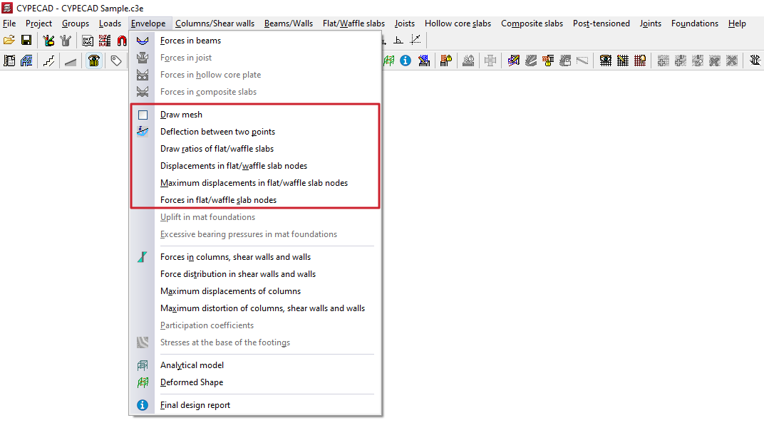
The menu options that allow the above information to be consulted are as follows:
- Draw mesh
- Deflection between two points
- Draw ratios of the flat/waffle slabs
- Displacements at slab/waffle slab nodes
- Maximum displacements at flat/waffle slab nodes
- Forces in flat/waffle slab nodes
Each of these features is detailed below.
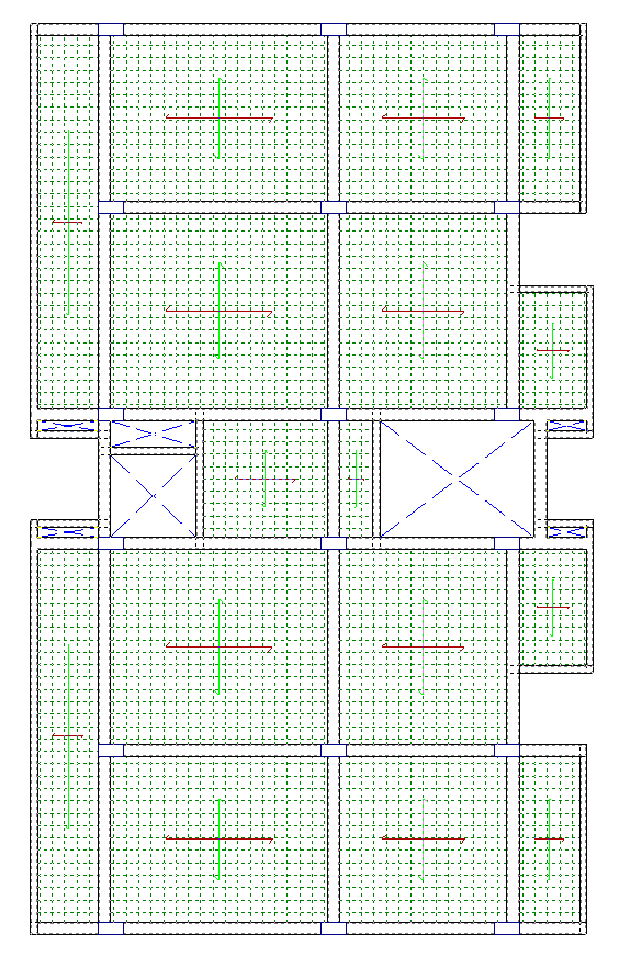
Draw mesh
The "Draw mesh" option allows the generated mesh in flat or waffle slab panels to be consulted by displaying it on screen.
| Note: |
|---|
| In the case of waffle slabs, the mesh spacing is one third of the centre-to-centre distance. In the case of slabs, the mesh is generated every 25 centimetres. |
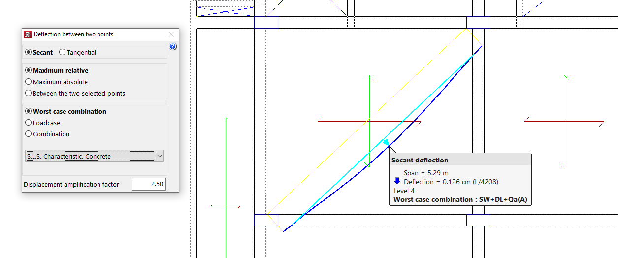
Deflection between two points
The "Deflection between two points" of the slab or bidirectional slab can be consulted using this menu option, as well as from the "Contour plots" tab.
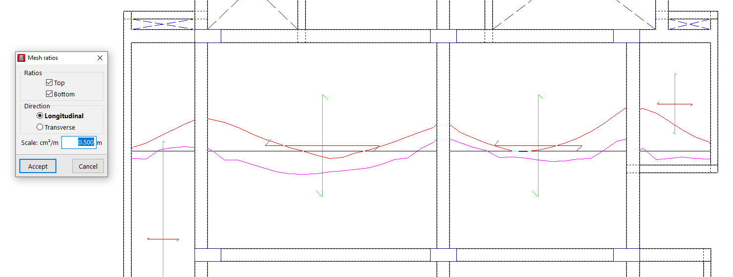
Draw ratios of the flatslab/waffle slabs
With the "Draw ratios of the flat/waffle slabs" option, the mechanical reinforcement ratios of each mesh alignment are displayed.
The program allows selection of the "Quantities" "Top" and "Bottom" in the "Longitudinal" or "Transverse" direction, as well as entering the value of the display "Scale".
After accepting, click on a point of a panel so that the quantity diagram of the alignment passing through it is displayed. By clicking on additional points, the quantity diagrams of other alignments can be made visible. Each diagram can be clicked to remove its display from the screen.
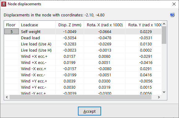
Displacements at slab/waffle slab nodes
Using "Displacements at slab/waffle slab nodes", it is possible to consult Z displacements and rotations about X and Y, by simple load cases, at any node of the mesh of a slab or waffle slab.
When moving the pointer over the different mesh nodes, their coordinates are also indicated.
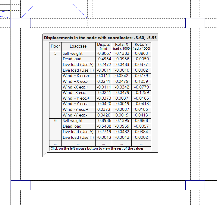
By clicking with the left mouse button, the "Node displacements" window opens, showing all the values for the node at those coordinates.
If there is more than one storey per group, the results for each storey are shown.
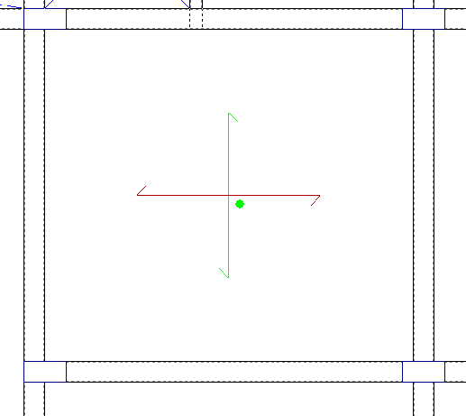
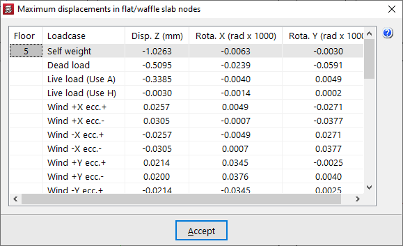
Maximum displacements at slab/waffle slab nodes
From "Maximum displacements at slab/waffle slab nodes", the maximum Z displacements and the maximum rotations about X and Y, by simple load cases, are displayed for each slab or waffle slab panel.
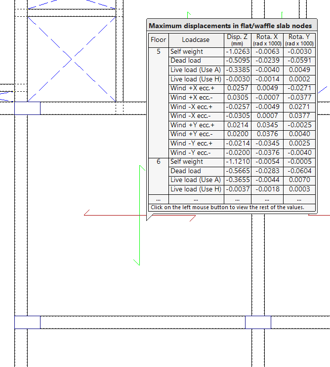
When clicking on each panel, a green circle appears indicating the position of the point of maximum displacement, together with a window showing the information on maximum displacements by load case.
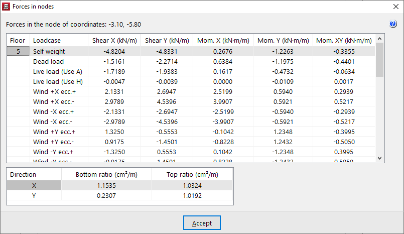
Forces in flat/waffle slab nodes
The "Forces in flat/waffle slab nodes" option allows the forces by simple load cases and the reinforcement ratios at any node of the mesh of a flat or waffle slab to be consulted.
When moving the pointer over the slab panel, the shear forces and bending moments per metre width of slab are shown, together with the values of "Bottom quantity" and "Top quantity" in both directions (X and Y) at the node indicated on screen, whose coordinates are also displayed.
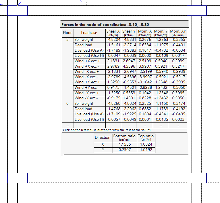
By clicking the left mouse button, a table with all the information described is obtained.
If there is more than one storey per group, the results for each storey are shown.