CYPECAD - Designing concrete block walls
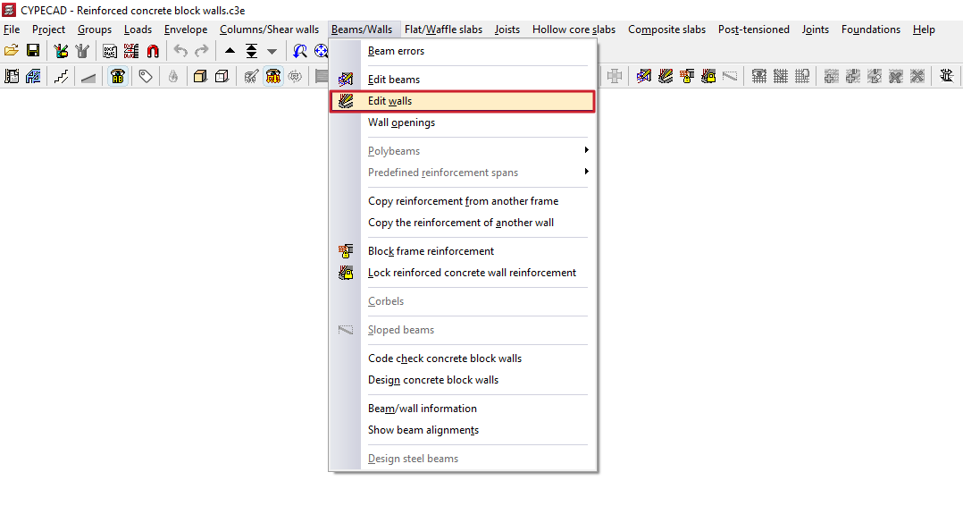
The reinforcement for concrete block walls is edited using the "Edit walls" option in the "Beams/Walls" menu on the "Results" tab.
When you click on this option and select a concrete block wall in the model, the "Edit block wall reinforcement" window will open, featuring two tabs: "Vertical reinforcement" and "Horizontal reinforcement".
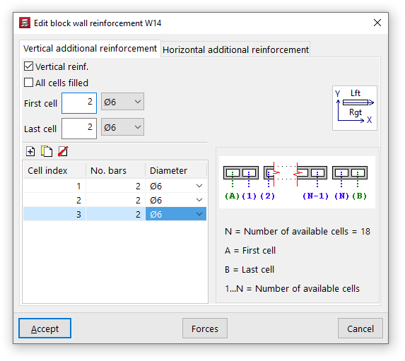
Vertical reinforcements
Vertical reinforcement bars are placed in the various cells of the block wall, for which they must be embedded.
To indicate the presence of this reinforcement, you must first tick the "Vertical reinforcement" box in the "Vertical additional reinforcement" tab.
Later on, you can enable the "All cells filled" option to take this condition into account in the wall.
You must specify the number of bars and their diameter for both the "first cell" and the "last cell" of the wall.
Finally, the table on the left allows you to optionally enter reinforcements in the remaining cells:
- On the right, the program will display a generic diagram of the wall. Below this, the "Number of available cells" in the wall is shown, numbered from 1 to N (excluding the first and last cells), whilst the first and last cells are labelled separately with the letters A and B.
- In this way, you can add reinforcement to the various cells by entering them into the table and specifying the "Cell index", along with the number of bars and their diameter.
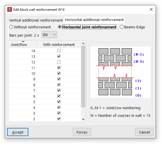
Horizontal reinforcements
Horizontal reinforcement consists of tie beams or belt beams placed at the various joints or courses of blocks in the wall.
On the "Horizontal additional reinforcement" tab, you can select one of the following three options:
- "Without reinforcement", if you do not wish to include horizontal reinforcement;
- "Horizontal joint bars", in which case reinforcement bars consisting of two bars per joint with the specified diameter shall be provided;
- or "Beams-Edge", in which case beam-type reinforcements consisting of four longitudinal bars of the specified diameter, tied together by stirrups of the specified diameter and spacing, shall be provided.
The table on the left allows you to add horizontal reinforcement bars to the various joints or courses of the wall:
- On the right, the programme will display a generic diagram of the wall. Below this, the "Number of courses in the wall" (N) is shown, along with the "Numbering of joints/courses" indexed from 0 to N-1. The base of the wall corresponds to joint number 0, whilst the joint between the penultimate and final courses is number N-1.
- This allows you to add reinforcement to each "Joint/Row" by ticking the "With reinforcement" box in the row corresponding to its number.