
Data assignment in beams ("Other options" menu)
The program offers the following tools for assigning data to beams in the "Other options" menu, within "Beams", on the "Beam input" tab:
- Assign covers
- Assign soil data
- Assign type of environment
- Assign service class
- Assign the slope angle of the compression struts
- Assign shear resistance
- Assign deflection limits
- Assign buckling coefficients
Each of these tools is described below:

Assign covers
The "Assign covers" option allows you to assign the covers to the beams defined in the "General project data" (within the "Project > General data" menu) or indicate some "Specific covers for the beam".
In the latter case, the dialogue box shows the "Top cover", the "Bottom cover" and the "Side cover".
| Note: |
|---|
| Since all beams in a frame must have the same covers, if different covers are defined, the program will automatically divide the alignments so that all the beams that comprise them meet this condition. |

Assign soil data
La opción "Asignar datos del terreno" permite escribir y asignar datos tanto a las "Vigas de cimentación" como a las "Losas apoyadas en el terreno".
En el cuadro de diálogo que aparece al pulsar sobre esta opción, es posible activar las casillas correspondientes para "Asignar el módulo de balasto", escribiendo su valor, y/o para "Asignar las tensiones admisibles" del terreno, escribiendo su valor tanto para "Situaciones persistentes" como para "Situaciones sísmicas y accidentales". El botón de la derecha permite "Importar valores usuales de proyecto" seleccionando un tipo de terreno entre los disponibles (como gravas, arenas, limos o arcillas).

Assign type of environment
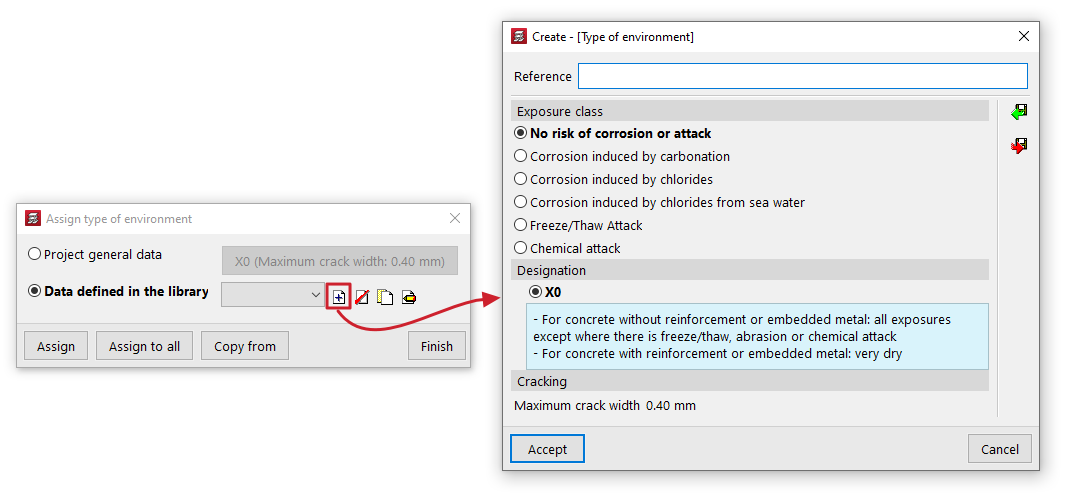
The "Assign type of environment " option allows you to assign the environment type to the beams by selecting the one defined in the "General project data" (which can be modified in the same dialogue box or in the "Project > General data") or indicate a different environment type from the "Data defined in library".
In the latter case, the type of environment is created by indicating a "Reference" and selecting the "Exposure class" and its "Designation", which gives a value of "Maximum crack opening".
Assign service class
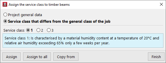
The "Assign service class" option allows you to assign the service class to the timber beams, either by selecting the class defined in the "General project data" (within the "Project > General data") or by indicating a "Service class different from the general one for the project".
In the latter case, you must select the "Service class" from those available in the dialogue box.
Assign the slope angle of the compression struts
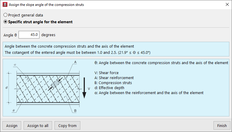
The "Assign the slope angle of the compression struts" option allows you to modify the slope angle of the compression struts with the axis of each part.
You can select the value defined in the "General project data" (in the "Project > General data > By position > Beam options > Dimensioning/Checking" menu) or enter a "Specific strut angle for the element".
Assign the shear resistance
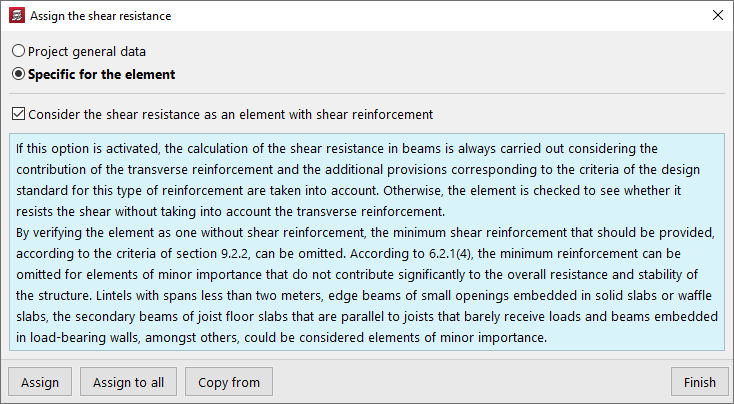
The "Assign shear resistance" option allows you to adjust the calculation of shear resistance in beams, either by using the settings defined in the "General project data" (in the "Project > General data > By position > Beam options > Design/Check") or by selecting a "Specific to the element" setting.
In this case, it is possible to activate or deactivate the checkbox "Consider shear resistance as a shear-reinforced element":
- If this option is activated, the shear resistance of beams is always calculated considering the contribution of transverse reinforcement, and the additional provisions corresponding to the criteria of the standard for this type of reinforcement are taken into account.
- Otherwise, it is first verified whether the element can withstand the required shear force without taking the transverse reinforcement into account.
Assign deflection limits
The "Assign deflection limits" option allows you to assign deflection limits to beams, either using those defined in the "General project data" (in the "Project > Beam options") or by selecting the limits from the "Data defined in library".
In this case, the dialogue box allows you to create and set deflection limits for beams made of different materials: "Concrete", "Rolled steel", "Formed steel" and "Timber".
By pressing the edit button on the right, you can configure the following arrow limits for each material:
- Instantaneous, by simple hypothesis type (Permanent load, Overload)
- Snapshot, by type of action combination (Characteristic, Frequent, Quasi-permanent)
- Infinite term, by type of combination of actions (Characteristic / Frequent, Quasi-permanent) (for "Concrete" and "Timber")
- Long-term active, by type of combination of actions (Characteristic, Frequent, Quasi-permanent)
In some cases, the wizard in the top right-hand corner allows you to import the deflection limit values from the "Design conditions" of the standards selected in the "General data".
The other options on the sidebar allow you to import and export the information on the configured deflection limits to .bibgen files saved on disk.

Assign buckling coefficients
The "Assign buckling coefficients" option allows you to define and assign the following parameters related to the buckling check of elements in compression and the lateral buckling check, both for steel beams and timber beams:
- Check buckling of elements in compression
In this section, by activating the boxes "XY buckling" and/or "XZ buckling" it is possible to define the "Buckling length" or the "Buckling coefficient" of the element, as well as the "Moment coefficient" in both planes. - Check lateral buckling
In this section, by activating the boxes "Positive bending (Top flange)" and/or "Negative bending (Bottom flange)" boxes, it is possible to define the "Lateral buckling length" or the "Lateral buckling coefficient" of the element, as well as the "Moment coefficient" in both wings. The "Critical moment modification factor" is also defined.

At the bottom of the dialogue box for each of these options, the "Assign" option allows you to select the beams in the floor plan to which the selected condition will be assigned, while "Assign to all" will apply the selected condition to all beams in the floor plan where possible. On the other hand, "Copy from" allows you to extract information from a specific beam on the floor plan to define the current beam. The "Finish" option allows you to end the operation without changes.