Defining timber joist floor slabs
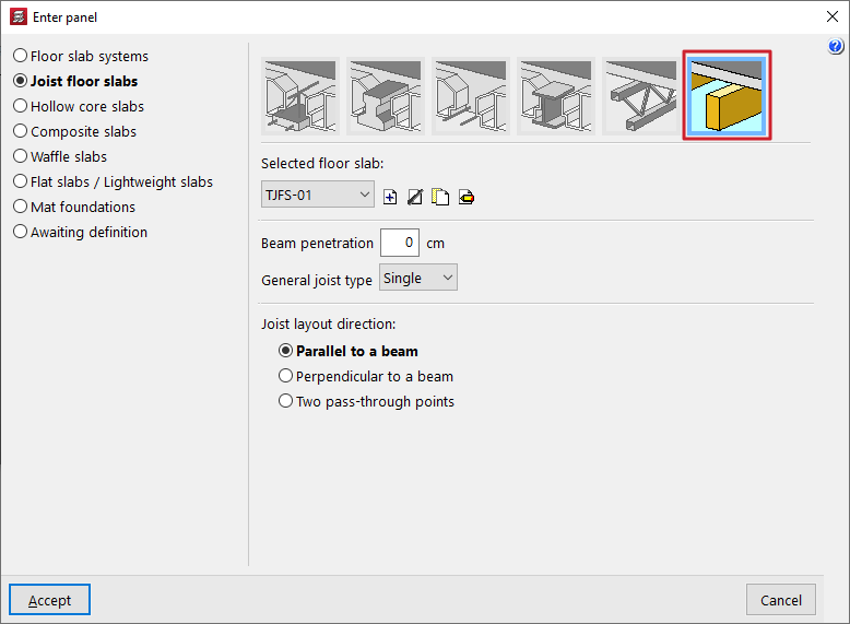
When defining timber joist floor slabs (in the "Enter floor" window), the user must select the "Selected floor slab" from those available in the project. The controls on the right allow you to "Add", "Delete", "Copy" or "Edit" these floor slabs.
When you use these controls, the program opens a window where you can configure each timber joist floor.
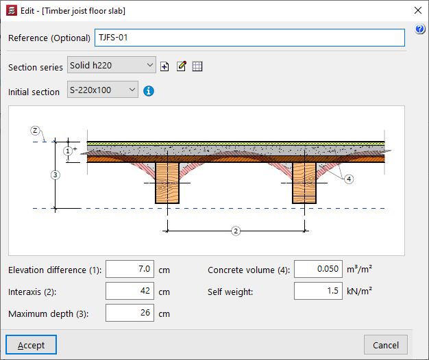
Here, a "Reference (Optional)" is entered first for the floor slab.
The two drop-down menus at the bottom then allow you to select the "Section series" to be used in the panel and the "Initial section" for the panel’s joists.
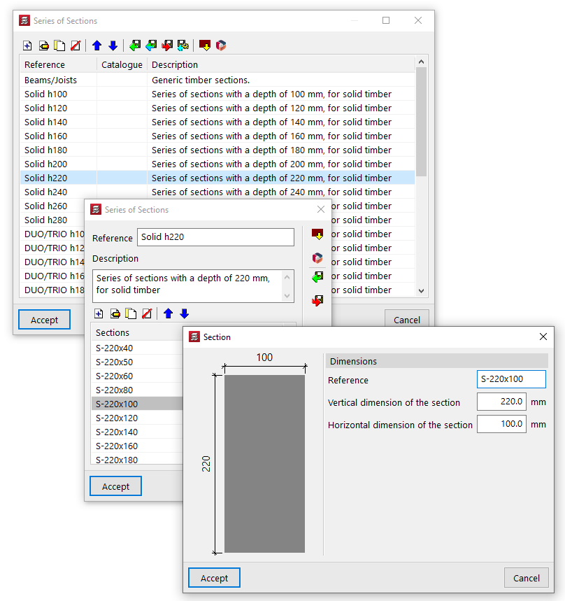
The controls to the right of the "Section series" area allow you to add, edit or manage the section series available in the project in a list.
In this list, as well as entering data manually and importing and/or exporting it to files on the hard drive, it is also possible to carry out the "Import of predefined section series" from various catalogues and reference guides included in the program.
Finally, the following parameters are defined:
- the "Elevation difference (1)" between the top surface of the joist and the reference level (Z);
- the "Interaxis (2)" between joists;
- the "Maximum depth (3)" of the floor structure, which includes the depth of the joists and that of the elements resting on them;
- the "Concrete volume (4)" used per unit area of the floor slab;
- and the value of the "Self weight" of the floor slab.
These parameters (1, 2, 3 and 4) are shown in the diagram of the timber joist floor structure in the centre of the window.