Editing and assigning reinforcement for top reinforcement in composite slab floors
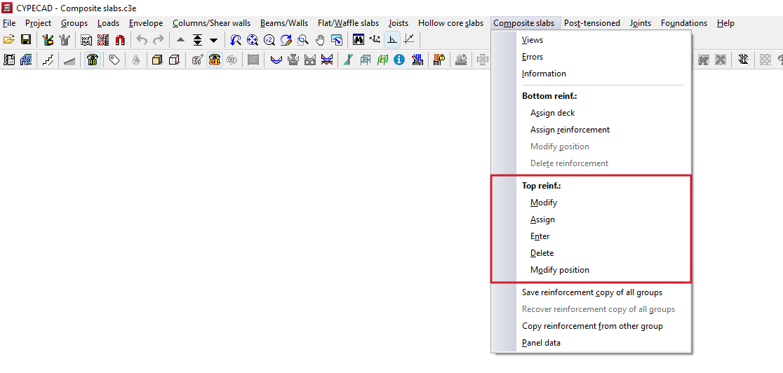
The tools in the "Top reinforcement" section of the "Composite slabs" menu, within the "Results" tab, allow you to modify the top reinforcement obtained in composite slab floors following the structural analysis.
Changes made using the tools in this section are not retained in subsequent redesigns; therefore, they should only be used during the final adjustment stage prior to printing or exporting the data.
Each of the available tools is described below.
Modify
The "Modify" option allows you to change the number, diameter and length of the reinforcement bars in the top reinforcement. It also allows you to add or remove layers or reinforcement groups.
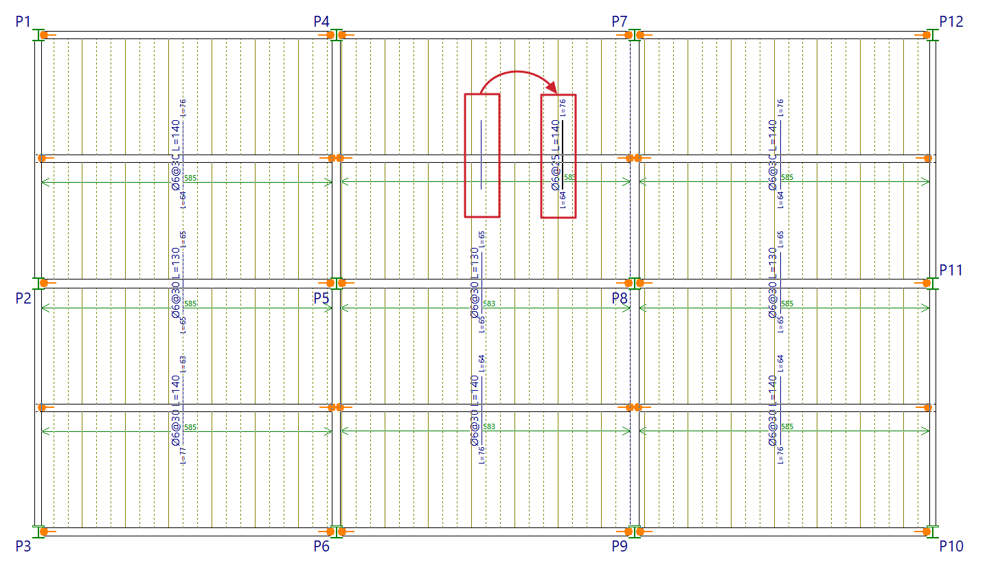
To do this, select the reinforcement to be modified by drawing a box on the plan view.
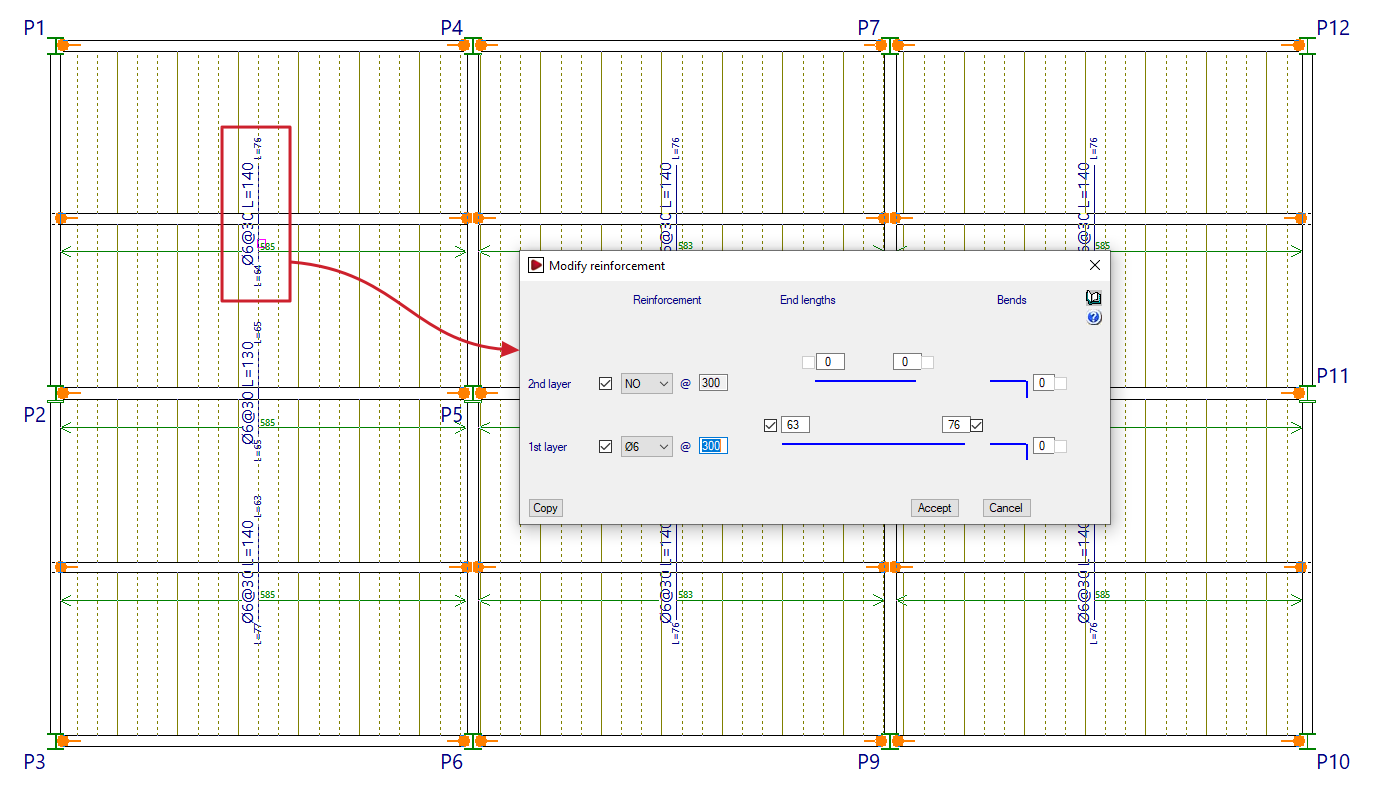
In the "Modify reinforcement" window that appears, you can modify the "Reinforcement" in the "1st layer" and "2nd layer" by specifying their number, diameter and spacing. You can also enter the "End lengths" (or the lengths of the reinforcement bars on either side of the beam axis), or the length of the "Extensions" (which the program adds in cases where the negative sections meet a slab edge).
The lengths of bars anchored in a straight extension are measured from the nearest beam centreline, whilst the lengths of bars anchored at the end indicate the length from the bend point.
The "Copy" option allows you to extract data from a selected negative assembly on the floor plan, whilst "Accept" applies the data entered in the window to the reinforcements selected when using the option.
Assign
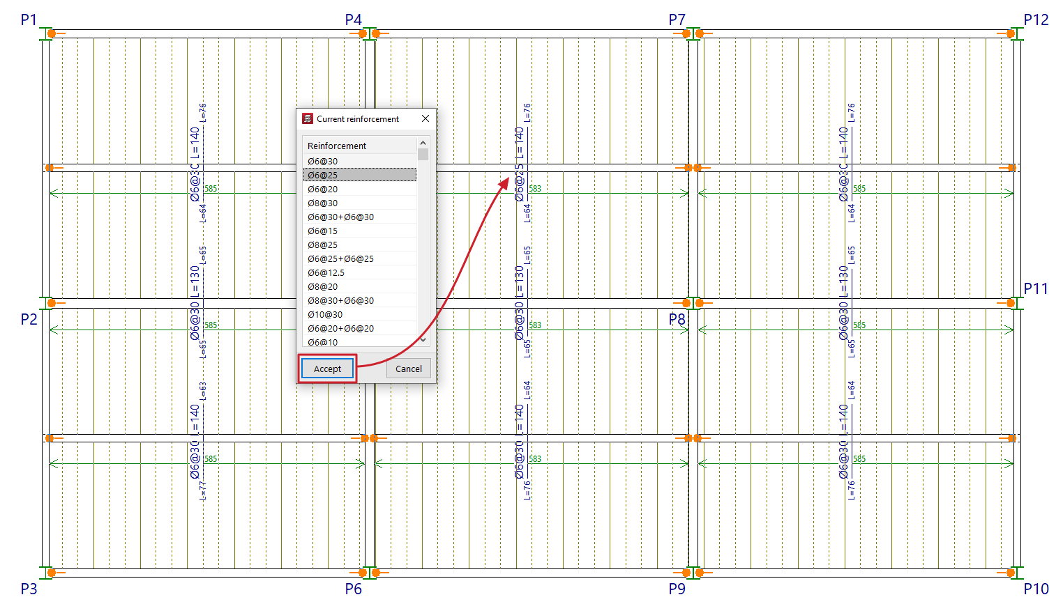
The "Assign" option allows you to change the diameters and spacing of the selected group of top reinforcement.
Right-clicking opens the "Current reinforcement" window, which allows you to select the reinforcement group to be assigned from those available in the top reinforcement table for composite slabs defined in the project.
Enter
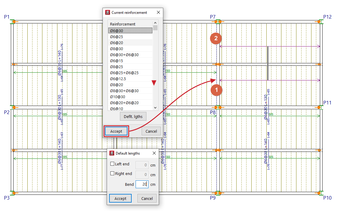
The "Enter" option allows you to insert top reinforcement bars on composite slabs.
When you click on the option, the pop-up window that appears when you right-click allows you to select the "Current reinforcement" from those available in the upper reinforcement table for composite slabs defined in the project. It is also possible to enter the "Default lengths" for the reinforcement to be placed, both at the left and right ends, as well as the length of the stirrup.
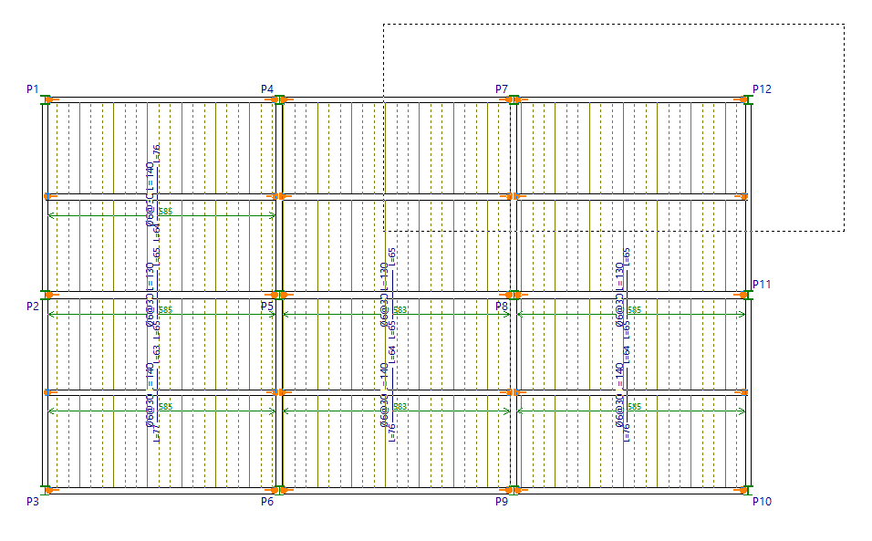
Next, left-click on two points on the plan view of a composite slab to position the reinforcement, either on both sides of an intermediate support (such as a beam), or near an edge support and at another point beyond the edge of the slab. In the box that appears, you will need to confirm the lengths of both ends, or of one of the ends and the length of the stirrup, as appropriate. The "Leng. betw." parameter indicates the distance between beam centres when inserting a continuous top reinforcement in a span. After accepting, the selected reinforcement will be drawn.
You cannot insert bars where reinforcement groups have already been defined: in this case, you must use the "Modify" option if you wish to add new bars or edit their data, or first delete the existing top reinforcement groups in order to use the "Enter" option.
Delete
The "Delete" option allows you to remove reinforcement bars from drawings.
To do this, the bars to be removed are selected using a selection box on the plan view.
Modify position
The "Modify position" option allows you to move the display of the flat sign from one bar to another point within the same bar. This can be useful when the flat sign label interferes with other text.
To change the position of the reinforcement display, click on the label text in the reinforcement slab width, then click on a point in the same slab width to define its new position.