Editing hollow core slabs
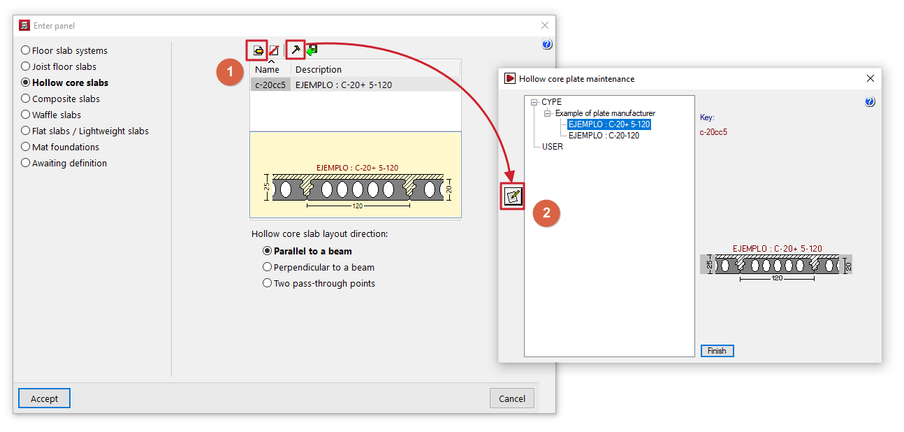
The "Edit hollow core slabs" window (accessible via "Enter panel", "Hollow core slabs slabs", "Edit" (1), or via the edit button within "Maintenance of hollow core slabs" (2)) allows you to view or enter the geometric data and mechanical properties of the selected hollow core slab.
This window allows you to view information provided directly by the manufacturers included in the program (in the case of hollow core slab floor systems from the Open BIM Database catalogues or manufacturer libraries) or, in the case of user-defined hollow core slabs, to enter the values for a specific slab that you wish to prefabricate or construct on site.
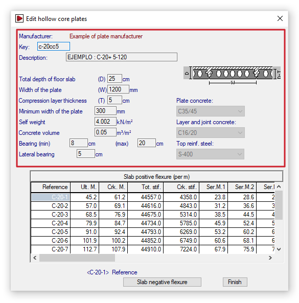
Defining the geometric and material properties of the plates
The geometric and material data provided by the program for each slab floor are as follows:
- Code
Identification of the plate tag using eight alphanumeric characters. - Description
Board name. - Total depth of the floor slab (C)
Total depth of the slab plus the compression layer, if any. - Width of the plate (A)
Plate width, or the distance between plates. - Compression layer thickness (E)
Thickness of the compaction layer, if any. - Minimum width of the plate
The minimum permitted width resulting from the longitudinal cut of a standard panel. Where a special panel of lesser width is produced, due to the dimensions of the panel section where it meets an edge, the width of this special panel must fall between the standard panel width and the aforementioned minimum permitted width. - Self weight
Weight per square metre of the complete floor structure. - Concrete volume
Volume of concrete in cavity fill, joints between slabs and the compression layer, if present. By default, the volume of the compression layer is used. - Minimum and maximum bearing
When the slab is offset from the normal to the support, the overhang differs at each edge of the slab and may vary between the minimum and maximum overhang values. If the maximum value is exceeded, the slab is chamfered. - Lateral bearing
This is the value by which the panel may deflect laterally when supported by a beam that is parallel to, or slightly offset from, the panel’s longitudinal direction. - Plate concrete / Layer and joint concrete / Top reinf. steel
This information is provided for reference purposes and indicates the materials used to calculate the section’s strength properties.
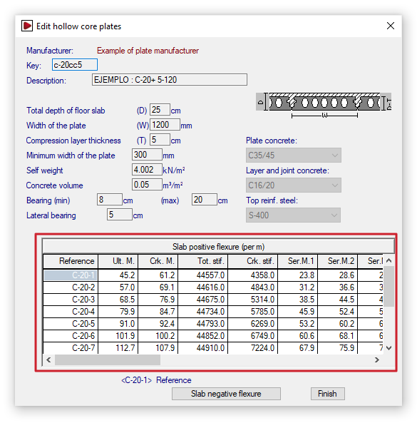
Entering the positive bending strength data for the plates
The structural data for the section are defined below:
- Positive bending of the floor slab (per metre)
This table is used to enter the structural data for the section under positive bending per metre of floor slab. The program allows you to define several slabs belonging to the same series. The following data is specified for each of them. This data corresponds to the section formed by the slab together with the joint-filling concrete and the compression layer, if present:- Reference
Reference number for each plate in the series. - Ultimate moment ("Ult. M.")
Maximum moment withstood (or ultimate moment). - Cracking moment ("Crk. M.")
Moment used to calculate deflection using the Branson method. - Total stiffness ("Tot. stif.")
Total stiffness of the composite slab-concrete section. This is used to form the stiffness matrix for the members into which the floor slab is discretised. - Cracked stiffness ("Crk. stif.")
Stiffness used to calculate deflection using the Branson method. - Service moments I, II and III ("Ser. M. 1", "Ser. M. 2", "Ser. M. 3")
Resisted moment according to the class in prestressed concrete:- Class I: structures in aggressive industrial or marine atmospheres, or in contact with aggressive soils or saline or slightly acidic water. This corresponds to Environment III.
- Class II: structures in normal, non-aggressive outdoor environments, or in contact with normal water or ordinary soil. This corresponds to Environment II.
- Class III: structures inside buildings or in outdoor environments with low humidity. This corresponds to Environment I.
- Ultimate shear ("Ult. S.")
The maximum shear force is withstood by the entire section, depending on whether the design moment (Md) is greater than or less than the unloading moment (Mg).
- Reference
If you are editing a panel record, the controls on the left allow you to add, delete or copy panels within the series.
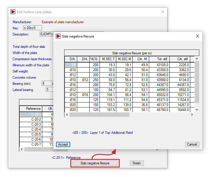
Entering the negative bending strength data for the slabs
Pressing the "Slab negative flexure" option at the bottom brings up the following table:
- Slab negative flexure (per metre)
This table is used to enter the structural data for the section under negative bending per metre of floor slab. It is possible to define different reinforcement combinations for each slab. Each row shows the mechanical characteristics of the section, taking into account that the load is distributed across the area subject to negative moments:- Diameter ("DIA.")/ Diameter ("DIA.") / Spacing ("SPACG.")
The two-diameter columns allow you to define two layers of top reinforcement with diameters that may differ. These reinforcement layers are arranged at the spacing specified in the third column. - Ultimate moment of the typical section ("M. SEC. T")
Negative moment withstood by the standard cross-section for the given reinforcement. - Ultimate moment of gross section ("M. SEC. M")
Negative moment withstood by the solid section for the given reinforcement. - Cracking moment ("Crk. stif.") / Total stiffness ("Tot. stif.") / Cracked stiffness ("Crk. stif.")
These parameters are used to calculate deflection using the Branson method. - Ultimate shear strength ("Ult. S.")
The maximum shear force that the section can withstand for the given reinforcement.
- Diameter ("DIA.")/ Diameter ("DIA.") / Spacing ("SPACG.")
As in the table above, if you are editing a panel’s record, the controls on the left allow you to add, delete or copy reinforcement combinations on the panel.