Editing walls
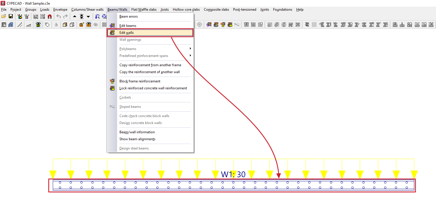
The "Edit walls" option, located in the "Beams/Walls" menu on the "Results" tab, allows you to view and modify the results obtained for the selected wall.
The editing window displays different options depending on the type of wall being edited.
Editing reinforced concrete walls
When editing a reinforced concrete wall, the program opens the "Reinforcement editing" window.
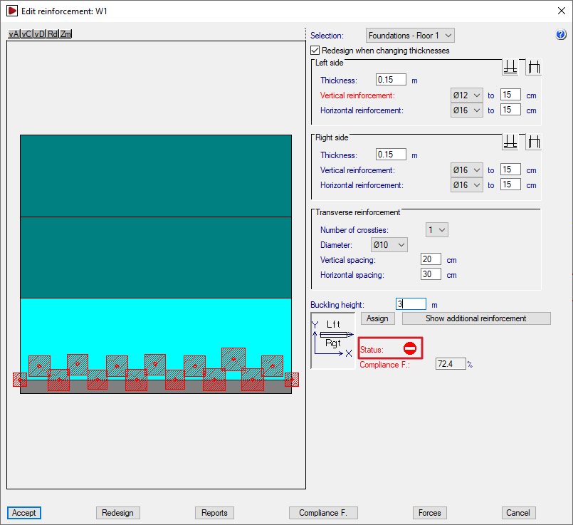
The elevation diagram on the left shows the wall in its full height. The section of wall between floors that is being examined is highlighted in cyan.
There are two ways to change the wall section: by selecting the desired section from the "Selection" drop-down menu, or by clicking on the diagram at the section where you wish to view the reinforcement.
The bottom of the page also shows a plan view of the wall, which includes the structure's general layout, the direction of the wall, and an indication of the positions of its left and right sides.
Checking and editing thicknesses and reinforcements
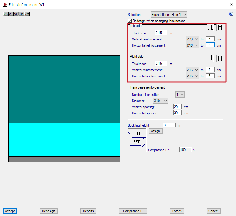
Once the selection has been made, the reinforcements for the section are displayed on the right.
If the "Redesign when changing thicknesses" option is enabled, the program will redesign and check the concrete section using the analysed forces whenever the thicknesses are modified in this window.
In the "Left side" and "Right side" sections, the program allows you to modify the following:
- the "Thickness" of each side of the wall;
- the diameters and spacing of the "Vertical reinforcement" and the "Horizontal reinforcement" on each side of the wall;
- and, using the relevant buttons, the "Overlap on upper floor" and "Start at floor base" on each side of the wall, as appropriate. The "Overlap length" is defined here.
If the "Thickness" label for the wall is displayed in red, this indicates that the concrete section is insufficient.
Similarly, if the labels on some of the reinforcement bars are shown in red, this indicates that those bars are insufficient to absorb the full load. In this case, additional reinforcement is provided at specific points as required.
| Note: |
|---|
| The lap and column start lengths are reanalysed if the vertical reinforcement is modified, with minimum lap or column start lengths always being applied, depending on the diameter and spacing of the vertical reinforcement. Where there is a significant change in the wall cross-section such that the reinforcement must be anchored at the base or on the top floor, the laps are analysed based on the forces at the top of the wall. |
Transverse reinforcement
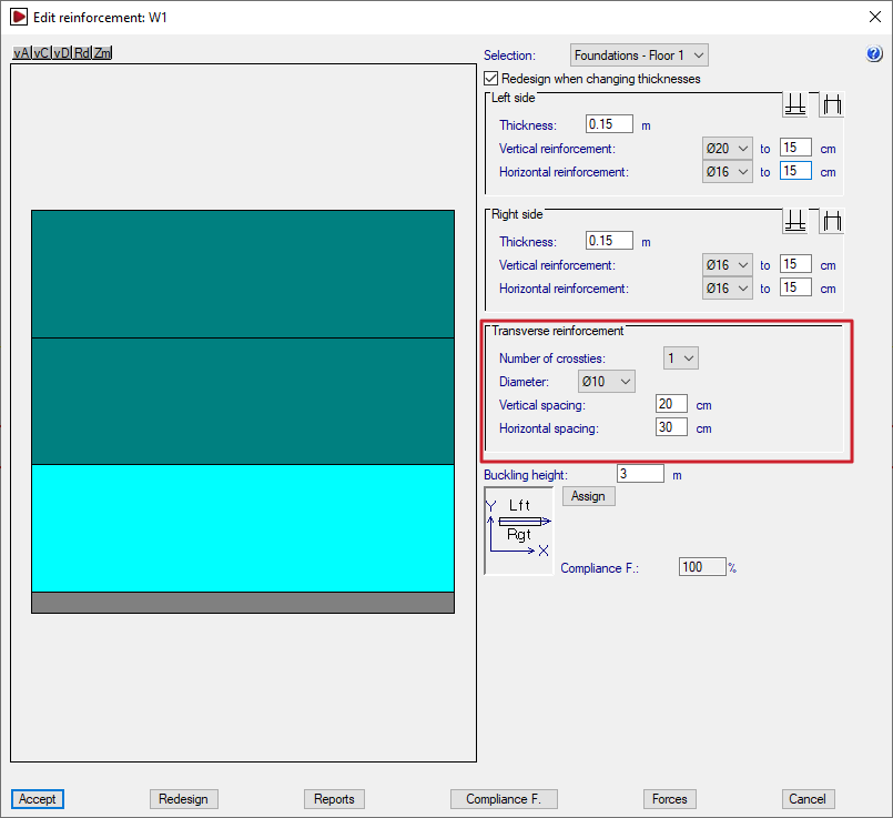
The "Transverse reinforcement" section allows you to modify the wall's transverse reinforcement. This is defined by the following parameters:
- the "Number of crossties" at each node;
- the "Diameter" of the bars;
- the "Horizontal spacing" and the "Vertical spacing". If this spacing is the same as that of the longitudinal reinforcement, it means that all the bars are tied. If the spacing of the longitudinal reinforcement is less than that of the transverse reinforcement (for example, 15 and 30, respectively), only some of the longitudinal bars between faces are tied (in this example, 1 in every 2 longitudinal bars).
As in the previous section, if the reinforcement or cross-section is insufficient, the text appears in red.
The proposed transverse reinforcement consists of one (or more, depending on the defined "Number of crossties") S-shaped branch connecting the bars between faces at all cross-joints between the wall’s longitudinal bars (horizontal and vertical), thereby linking the reinforcement on both sides of the wall.
Buckling height
The program analyses and displays the value of the "Buckling height" for the selected wall section in the corresponding field. This value affects the slenderness check in the various standards, where applicable. In any case, this value can be modified by the user.
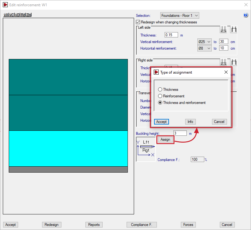
Assigning thicknesses and reinforcements
The "Assign" option allows you to copy the thickness and/or reinforcement of the section being edited to other wall sections, depending on the option selected.
When clicking "Accept" in the dialogue box that appears, the sections with a thickness and/or reinforcement matching the selected settings will be highlighted in light cyan, and the rest in dark cyan.
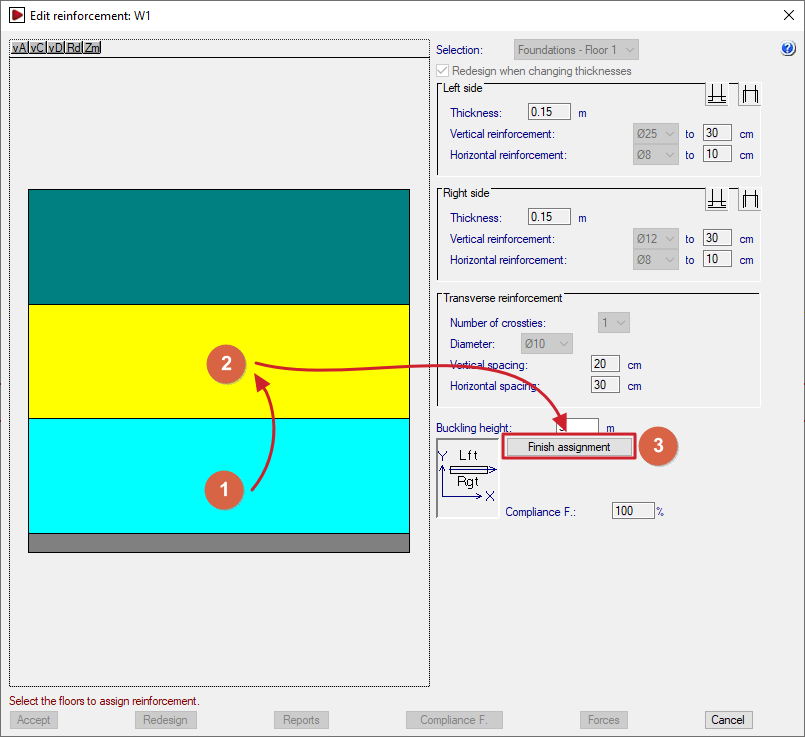
Next, use the mouse to select the sections to which you wish to apply the properties of the selected section. Each section you select will turn yellow.
To complete the operation, click on "Finish assignment".
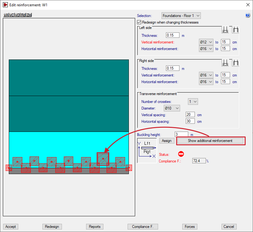
Additional reinforcement
You can view the additional reinforcement by clicking on "Show additional reinforcement" and double-clicking on each red square shown on the wall elevation drawing.
These points correspond to the control nodes of the finite element mesh that discretises the wall, such as the vertices and midpoints of the triangles that make it up.
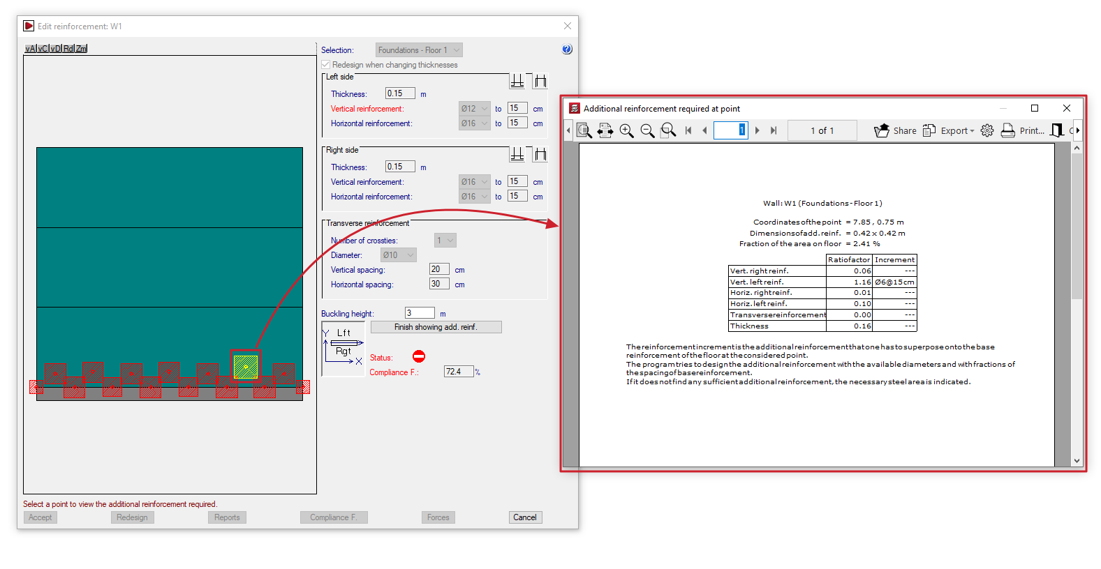
This opens the "Additional reinforcement required at point" window, displaying information such as the following:
- the reference number of the wall and the section in question;
- the "Point coordinates" of the reinforcement in question, the "Reinforcement dimensions", and the "Proportion of the floor area";
- for each type of reinforcement (vertical and horizontal reinforcement on both the right and left sides of the wall, and transverse reinforcement), the "Quantity factor" and, where applicable, the "Reinforcement increment" required to achieve the analysed steel cross-section, specifying the diameter of the bars and their spacing. The reinforcement increment is the reinforcement that must be added to the base reinforcement of the wall section at the point in question.
To finish viewing the additional reinforcement, click on "Finish showing add. reinf.".
| Note: |
|---|
| The program attempts to dimension the reinforcement using the available diameters and fractions of the base reinforcement spacing. If no suitable reinforcement is found, the required area of steel is indicated. |
Checking the status of the wall
In the "Status" section, the program alerts the user to situations such as the following in the section of wall being examined, so that the user can assess them and/or take steps to correct them:
- If the prohibited symbol appears, the concrete section is failing due to oblique compression, and the calculated safety factor falls short of the required value.
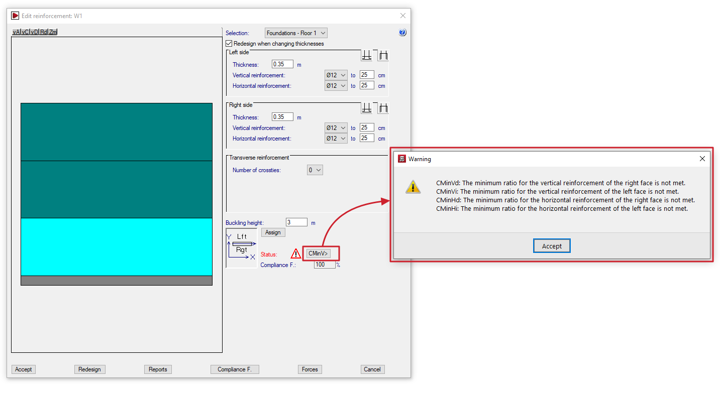
- If the warning symbol appears, which is less serious than the previous symbol, a button displaying an error code will be shown; clicking this button will open an information dialogue box. Possible warning scenarios include the following, which cover various regulatory breaches.
- If the concrete section or thickness is insufficient:
- Ee: The thickness is insufficient due to slenderness error.
- Er: There is no lever arm for the determination of the reinforcement. Increase the thickness or reduce the covers..
- If the reinforcement used is of a smaller size than required or has a diameter below the minimum:
- CMinVd: The minimum ratio for the vertical reinforcement of the right face is not met.
- CMinVi: The minimum ratio for the vertical reinforcement of the left face is not met.
- CMinHd: The minimum ratio for the horizontal reinforcement of the right face is not met.
- CMinHi: The minimum ratio for the horizontal reinforcement of the left face is not met.
- CMinT: The minimum geometrical ratio for the transverse reinforcement is not met.
- DMinT: The diameter of the transverse reinforcement is smaller than the minimum.
- if the required transverse reinforcement has not been defined, or if the spacing of the longitudinal bars it ties has been defined incorrectly:
- Ai: No transverse reinforcement has been provided, but it is necessary for the tying of vertical bars by Code.
- At: All vertical bars must be tied to the transverse reinforcement.
- SepSim: No transverse reinforcement has been installed, but the code requires the vertical bars to be tied together.
- If the concrete section or thickness is insufficient:
Wall compliance factor
The "Compliance factor" field displays the calculated compliance factor, i.e. the percentage of nodes in the section under review that comply with the specified configuration.
If the calculated compliance factor is less than 100%, areas marked with red squares will appear on the wall diagram, indicating that localised reinforcement is required.
The required compliance factor can be changed using the relevant option at the bottom of the wall editing window.
| Note: |
|---|
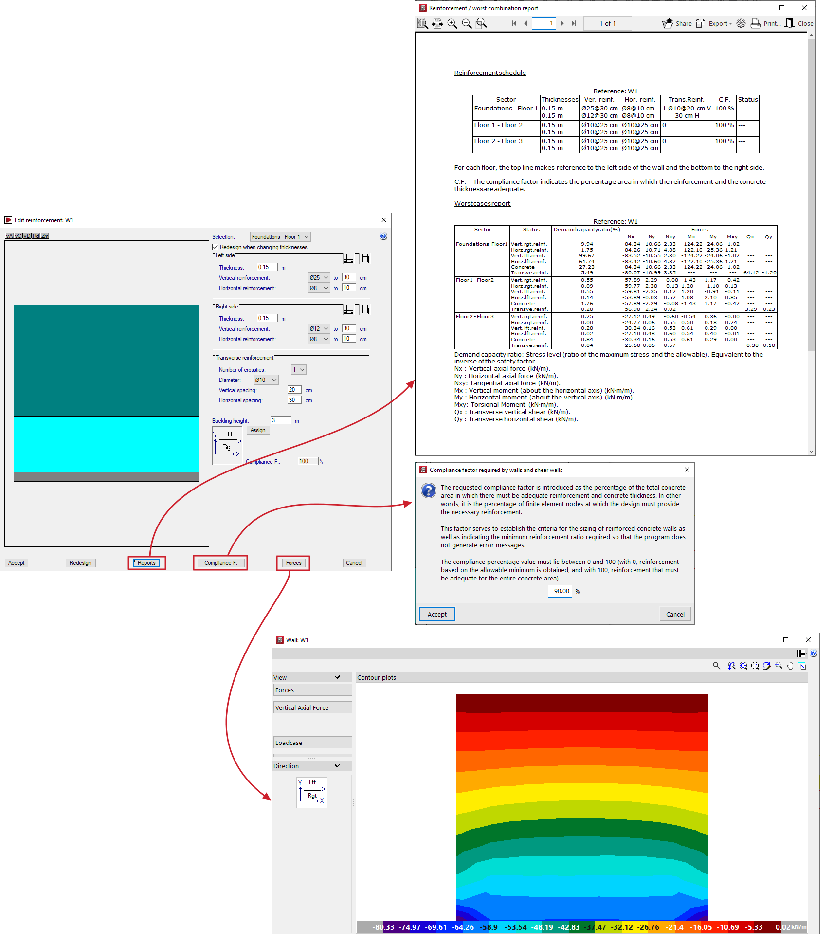
| The required compliance factor is defined as the percentage of the total area of the concrete enclosure in which the specified reinforcement and thickness must be sufficient. This factor is used both to establish the design criteria for walls and to determine the minimum area in which a reinforcement arrangement is valid, thereby reducing the number of error messages generated. The percentage value must be between 0 and 100: 0% results in minimum reinforcement, and 100% results in reinforcement that complies throughout the entire concrete space. |
Additional options
The options at the bottom of the window allow you to perform the following actions:
- Accept
Accepts the changes made and exits the wall editing window. - Redesign
Allows you to rebuild and redesign the wall if changes are made to the thicknesses or the required compliance factor. - Reports
Allows you to generate a "Reinforcement schedule" (which includes thicknesses, the compliance factor and the status) and a "Worst cases report" (axial, bending, shear and torsional) for the concrete and each reinforcement bar in each section of the wall (including the demand capacity ratio or the ratio of maximum stress to allowable stress). - Compliance factor
Allows you to change the required compliance factor. If this value is changed, you must then redesign the wall using the relevant button, after which the program will calculate and display a new compliance factor. - Forces
This opens a window displaying the forces in the wall, similar to the one that appears when you select the "Force distribution in shear walls and walls" option from the "Envelopes" menu. - Cancel
Discards the changes made and exits the wall editing window.