Forces in columns, shear walls and walls
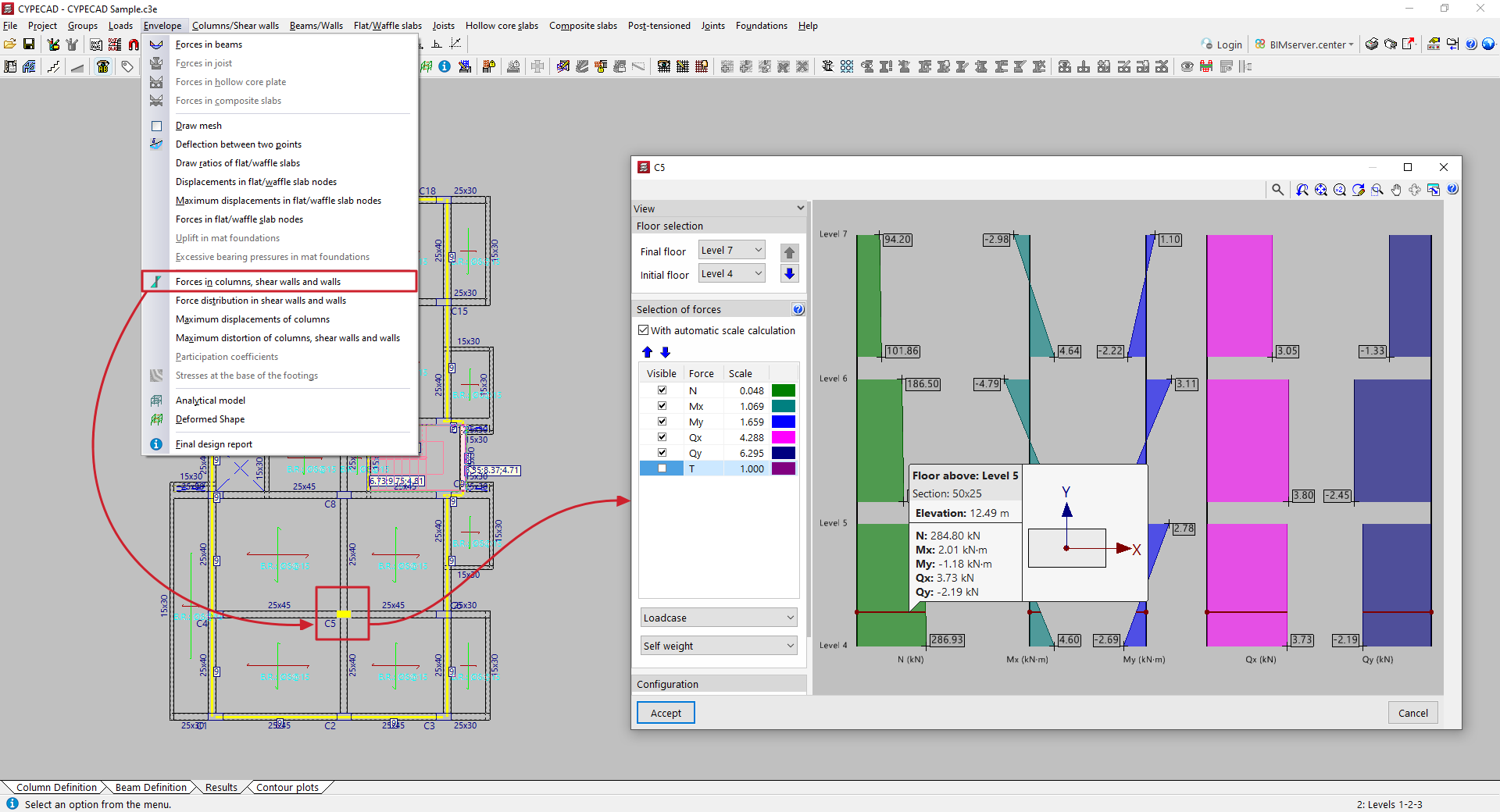
To view the forces in columns, shear walls and/or walls in CYPECAD, after analysing the structure, open the "Results" tab and go to a group where any of these elements are visible.
Next, open the "Envelope" menu at the top of the interface.
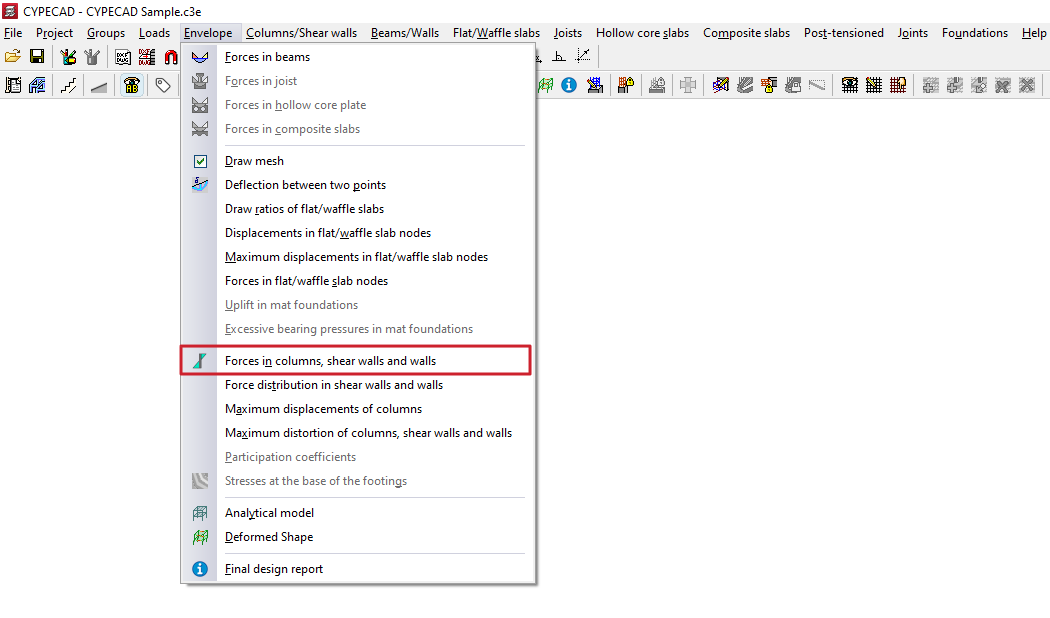
Forces in columns, shear walls and walls
Selecting the "Forces in columns, shear walls and walls" option and clicking on a column or wall opens a window where you can view their stress laws for simple loadcases or combinations of loadcases. In the case of diagrams, click on the segment of the diagram you wish to view.
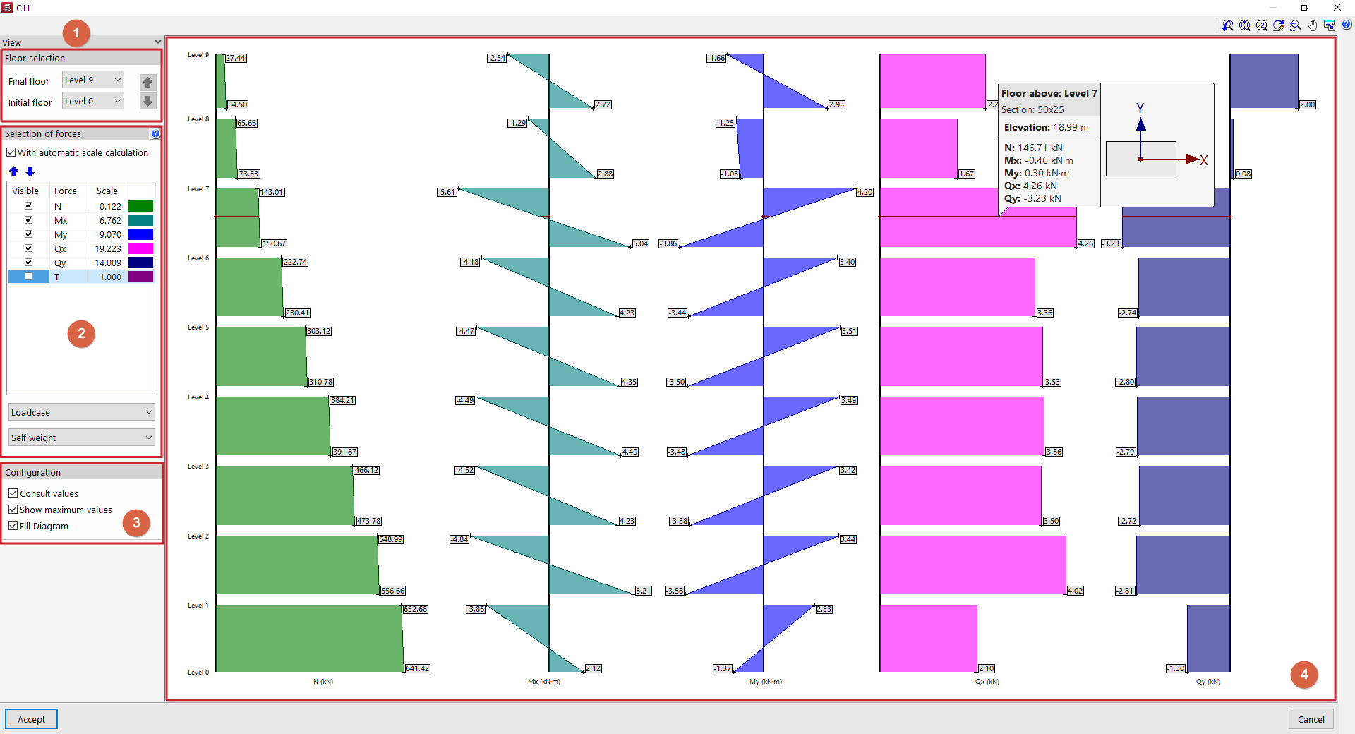
In the pop-up window, the following configuration options appear in the "Views" section on the left-hand side:
- In "Floor selection" (1), you can select the floors to be displayed by indicating the "Final floor" and the "Initial floor". The blue arrows allow you to scroll between floor sections.
- Next, in the "Selection of forces" section (2), it indicates for each stress whether it is "Visible" or not, along with its "Scale" factor and colour. If "With automatic scale calculation" is enabled, the program will adjust the size of the stress laws to the visible area on the screen, forcing the scale factor. The following can be included:
- the axil (N);
- the moments in both directions (Mx, My);
- the cutting edges in both directions (Qx, Qy);
- and the torsion (T).
- In the drop-down menus at the bottom of the "Selection of forces" section, select the "Loadcase" or "Combination" you wish to consult.
- Finally, within the "Configuration" section (3), the following options can be enabled:
- "Consult values", to display an information box when hovering over the stress laws;
- "Show maximum values", to make the values visible in each section;
- and "Fill Diagram", so that the stress laws are represented filled with a different colour.
In the viewer (4) on the right-hand side, hover the pointer over the stress laws for the column, screen or wall so that the program displays the floor plan, section, elevation and stresses in the same, as well as a diagram of the element in plan view showing its local axes.
The stresses in X are those contained in the local XZ plane of the element, and similarly, the stresses in Y are those contained in the local YZ plane.