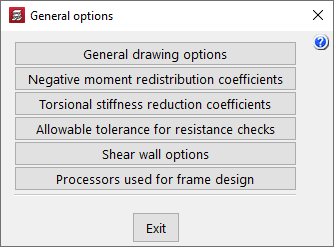
General options on the "Beam definition" tab
The "General options" in the "Project" menu, within the "Beam definition" tab, configure the following parameters relating to the drawing and design of various structural elements:
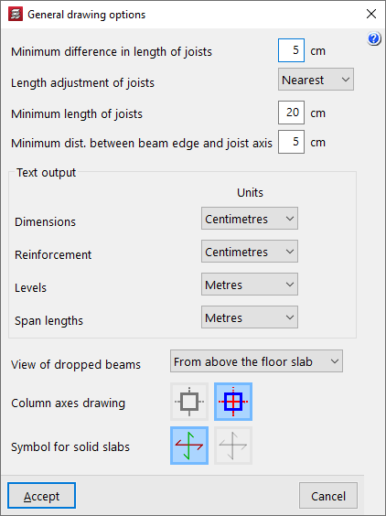
General drawing options
This option opens a dialog box where you can adjust the following drawing settings:
- The "Minimum difference in length of joists" field defines the rounding value for joist lengths when drawing the floor plan. If you enter 0, the actual lengths will be shown on the plan.
- In the "Length adjustment of joists" drop-down menu, you can specify whether the rounding of the joist lengths should be to the next higher value ("Excess"), the next lower value ("Deficit") or the nearest value ("Nearest").
- If a joist is shorter than the length specified under "Minimum length of joists", it will not be drawn.
- On the other hand, if a joist running parallel to a beam is positioned at a distance shorter than that specified in "Minimum distance between beam edge and joist axis", it will not be drawn.
- In the "Text output" section, you can define the units to be displayed for the "Dimensions" of elements, their "Displacements", the "Levels" and the "Span lengths".
- In the "View of dropped beams" drop-down menu, you can choose to have exposed beams drawn on the floor plan as if viewed "From above the floor slab" or "From below the floor slab", both on-screen and in the drawings.
- Finally, you can choose the "Column axes drawing" and the "Symbol for solid slabs" from those available.
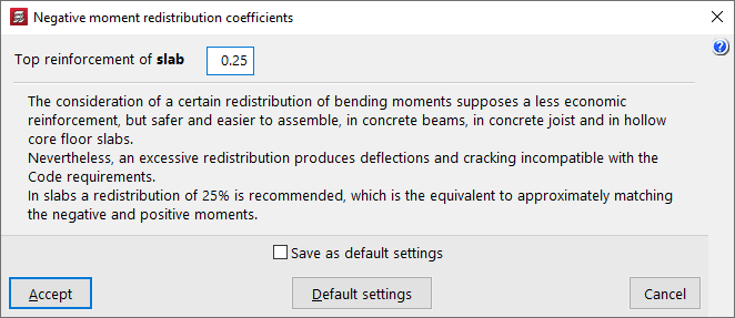
Negative moment redistribution coefficients
In the "Top reinforcement of slab" field, you can enter the value of the redistribution coefficient for negative moments in floor slabs, expressed as a ratio of 1:1, between 0 and 0.30.
| Note: |
|---|
| Allowing for a certain degree of redistribution of bending moments results in a more expensive but safer and more structurally sound reinforcement scheme for concrete beams, concrete joist floors and lightweight slabs. However, excessive redistribution results in deflections and cracking that are incompatible with the partition walls. In floor slabs, a redistribution of 25% is recommended, which is equivalent to approximately balancing the negative and positive moments. |
Torsional stiffness reduction coefficients
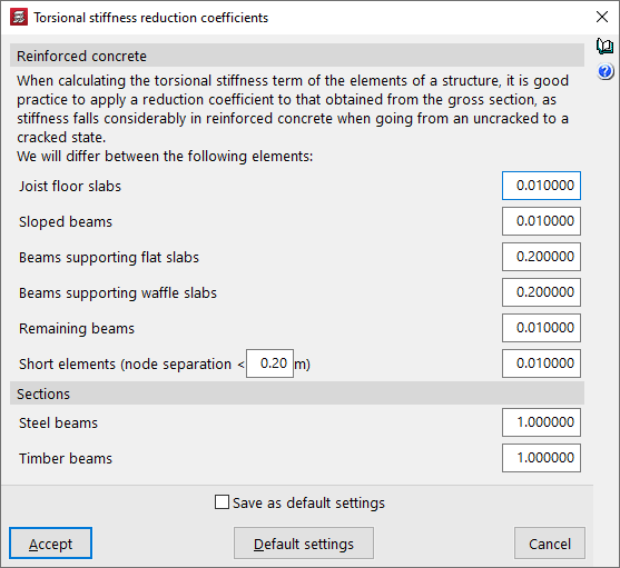
This option opens a dialog box where you can define the torsional stiffness reduction factors for the structural members.
Section: "Reinforced concrete"
In reinforced concrete members, stiffness decreases as the structure transitions from an uncracked to a cracked state. It is therefore advisable to apply a reduction factor to the torsional stiffness value obtained for the bare section.
These coefficients apply to concrete elements and do not include steel, composite or foundation beams.
The reduction factor can be adjusted for the following items:
- Joist floor slabs
The coefficient defined in this section applies to the webs of joist slabs, lightweight slabs and composite slabs. - Sloped beams
The coefficient defined in this section applies to sloped beams entered using the "Sloped beams" option in the "Beams" menu. - Beams supporting flat slabs / Beams supporting waffle slabs
The coefficient defined in this section applies to beams supporting solid or grid slabs. In these cases, it is sufficient for any of these types of slab to be in contact with the beam at any point for the entire beam to take on the value defined here. If a beam is in contact with several types of slab, it will take the highest of the reduction factors associated with the slabs. - Remaining beams
The coefficient defined in this section applies to all beams supporting one-way slabs that are not in contact with grid slabs or slabs. - Short beams (node separation < 'x' m)
The coefficient defined in this section applies to beams shorter than the specified distance between nodes. This is identical to the "Remaining beams" case, but in this instance, both the length and the value of the coefficient to be applied can be modified.
"Sections" area
Here you can define reduction factors for "Steel beams" and "Timber beams", respectively.
Allowable tolerance for resistance
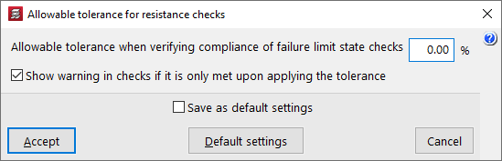
This option opens a dialogue box where you can set the "Allowable tolerance when verifying compliance of failure limit state checks". To do this, enter a percentage value.
If you tick the box below, you can choose to "Display a warning during checks if the condition is only met when the tolerance is applied".
Options for retaining walls
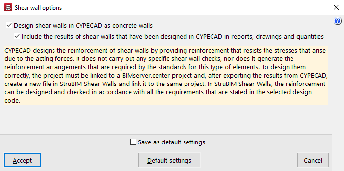
By ticking the boxes in this dialogue box, you can "Design shear walls in CYPECAD as concrete walls" and, where applicable, "Include the results of shear walls that have been designed in CYPECAD in reports, drawings and quantities".
| Note: |
|---|
| CYPECAD designs the reinforcement for shear walls by arranging the reinforcement to withstand the stresses imposed by the applied forces. It does not perform specific checks for shear walls, nor does it generate the reinforcement layouts required by standards for this type of element. To design them correctly, you must link the project to a BIMserver.center project and, after exporting the results from CYPECAD, create a new file in the StruBIM Shear Walls program and link it to the same project. In the StruBIM Shear Walls program, you can design and verify reinforcement in accordance with all the requirements of the selected standard. |
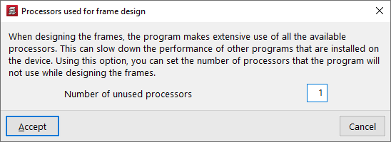
Processors used for the design of portal frames
The "Number of unused processors" option allows you to specify the number of processors that the program will not use whilst performing the frame analysis.
| Note: |
|---|
| The design of portal frames makes extensive use of all available processors. This can mean that, whilst the program is designing the portal frames, the performance of the computer when running other programs may be reduced. |