Inserting and managing wall pressure conditions
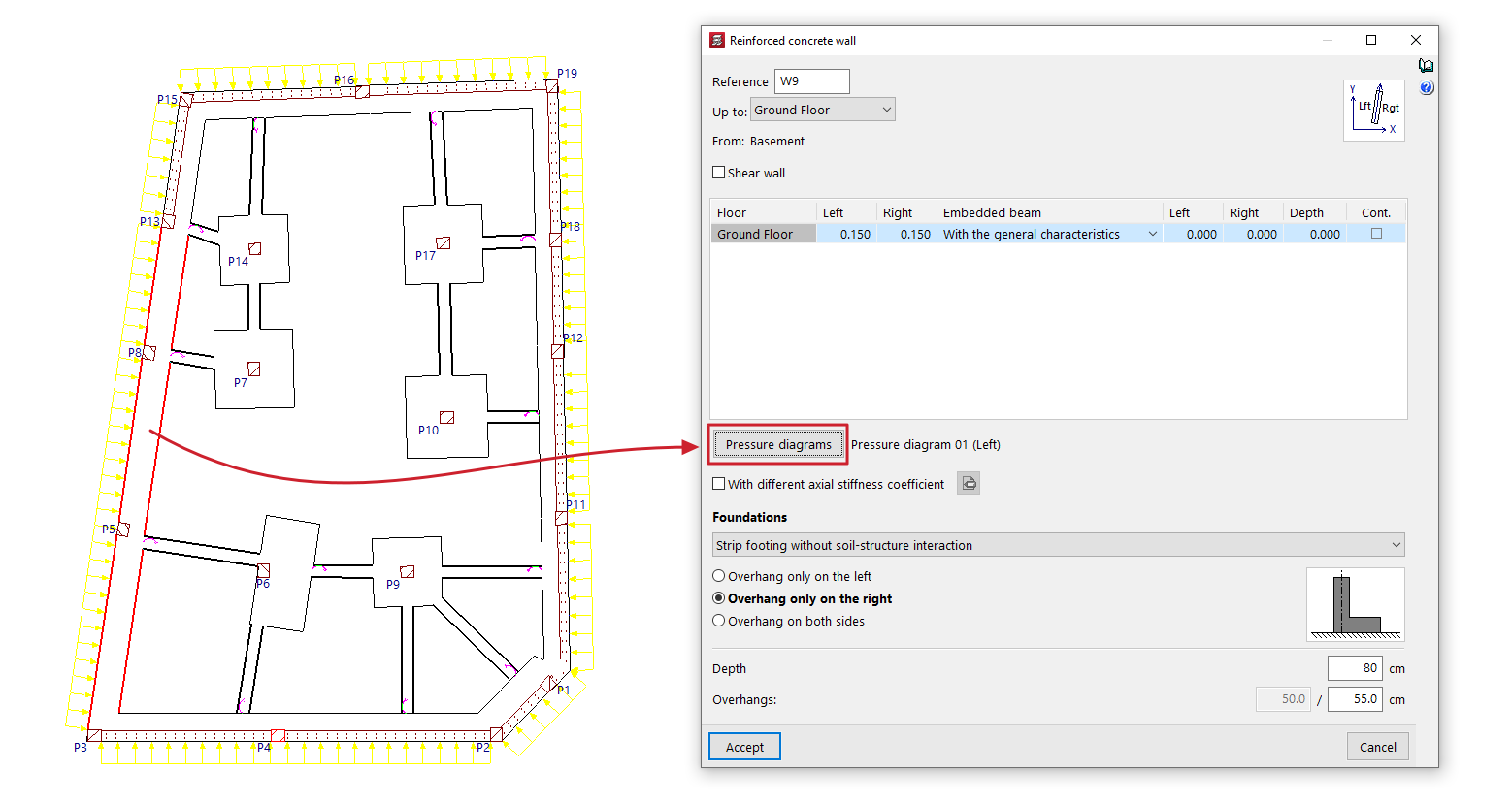
To define wall pressure conditions, open the "Beam Input" tab, select the "Walls" menu, and choose either "Add Wall" or "Edit".
Next, click the "Pressure diagrams" option in the wall editing window to access the interface that allows you to create, manage and apply pressure diagrams to the wall being entered or edited.
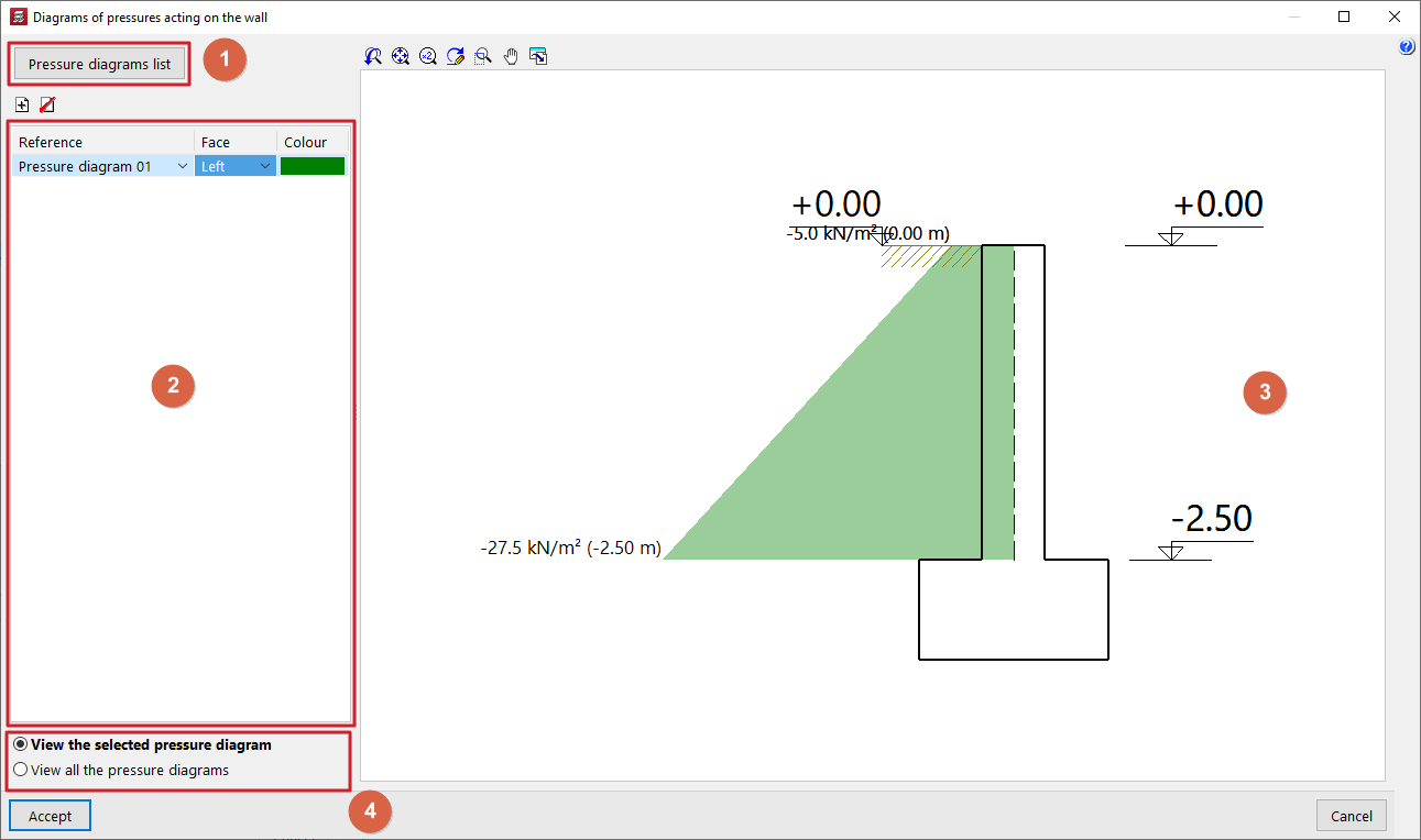
Diagrams of pressures acting on the wall
The "Diagrams of pressures acting on the wall" window opens when you click the "Pressure diagrams" option in the wall editing panel and displays the following sections:
- In the top-left corner (1) is the "Pressure diagrams list" option, which opens the window of the same name, where the pressure diagrams available throughout the project are defined and managed.
- On the left-hand side (2), there is a table showing the pressure conditions applied to the wall that is being entered or edited. To apply a pressure condition to the wall and add an entry to the table, click on the corresponding option at the top. The following data is defined for each entry:
- In the "Reference" column, select the pressure diagram you wish to apply from the drop-down menu. To apply a pressure diagram, it must first have been created in the "Pressure diagrams list" window.
- The "Face" column indicates whether the pressure diagram applies to the "Left" or "Right" face of the wall. If the loads are visible, it is possible to check later on the plan view that the pressure diagram has been applied to the correct face of the wall.
- In the "Colour" column, select a colour to be displayed in the sectional view on the right-hand side of the window.
- In the centre-right section (3), a viewport displays the cross-section of the wall being entered or edited, along with a representation of the pressure rule or rules applied to it, coloured according to the selected colours. For each diagram, the pressure values at each elevation are labelled. In addition, the elevations of the wall heights, the fill elevation, the water table and the elevation of the rock layer are shown.
- Using the options in the bottom right-hand corner (4), you can either "View the selected pressure diagram" in the viewer only, or simultaneously "View all the pressure diagram" defined in the table and applied to the wall.
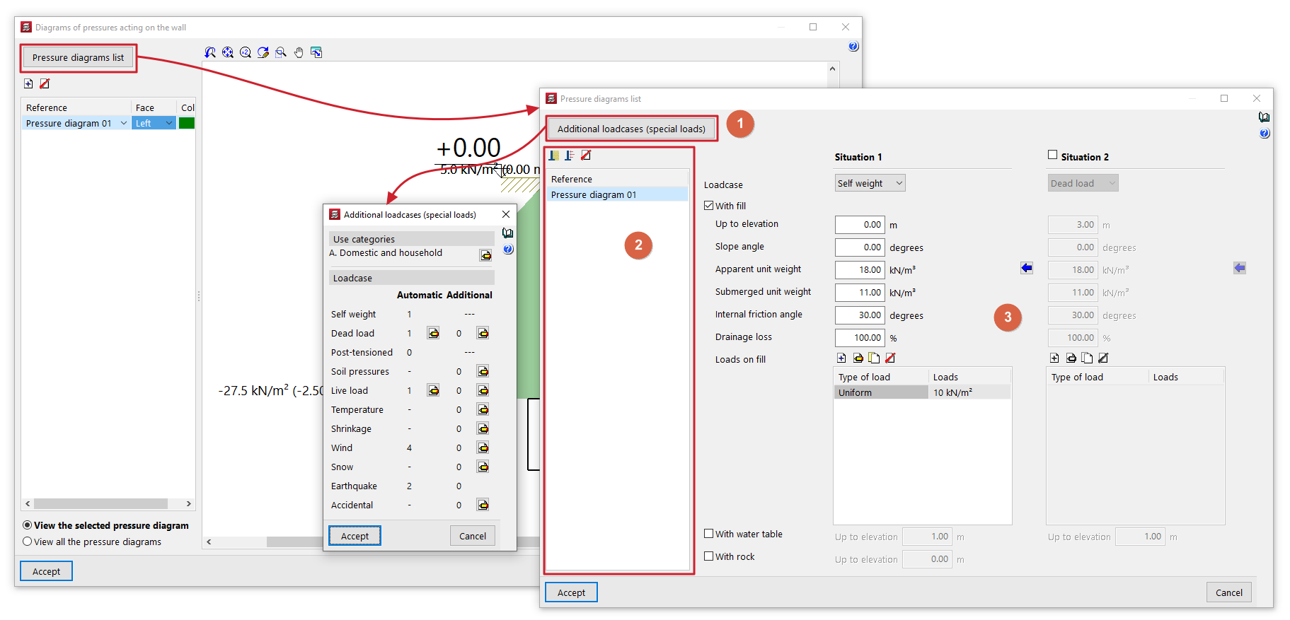
Management of the list of pressure regulations
The "Pressure diagrams list" window allows you to create and manage the pressure diagrams available for the project. These diagrams can then be applied to each wall using the options in the "Pressure diagrams on the wall" window.
This window displays the following sections:
- In the top-left corner (1) is the "Additional load scenarios (special loads)" button, which provides direct access to the management panel for the load scenarios available for the project.
- The left-hand side (2) displays the list of pressure diagrams available in the project. To create a pressure diagram and add an entry to the table, click on the "Soil pressure" or "Generic pressure diagram" button at the top. The reference for the diagram can be edited directly in its table cell. It is also possible to delete the selected pressure diagram using the corresponding button at the top.
- The central right-hand section (3) displays the parameters that define the pressure diagram selected on the side. This section varies depending on whether you are editing a "Soil pressure" or a "Generic pressure diagram".
Further down, in the "Project data" section, the generic thrusts and pressures defined for the project will be listed, along with the walls on which these forces act.