Inserting composite slabs
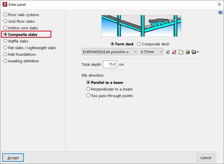
The "Composite slabs" option, within the "Enter panel" window (accessible via "Panels > Panel manager"), allows you to enter composite slabs made of sheet metal used solely as permanent formwork or as composite slabs.
Selecting the type of composite slab
The type of composite slab to be entered is selected using the options at the top of the "Enter panel" window:
- Permanent formwork
This option allows you to define composite slabs with non-load-bearing sheet metal:- During the construction phase, the sheet metal is used as permanent formwork. The sheet metal is capable of supporting its own weight, the weight of the fresh concrete and the construction loads on its own.
- During the service life, the sheet metal does not contribute to the structure’s load-bearing capacity; only the reinforced concrete slab provides structural support.
- Composite sheet metal
Allows you to define composite slabs using composite sheet metal:- During the construction phase, the sheet metal acts as permanent formwork.
- During service, the sheet metal is considered to form a structural bond with the hardened concrete, acting as tensile reinforcement and resisting positive moments in the finished floor slab. The sheet metal is capable of transmitting shear stresses at its interface with the concrete provided that mechanical interlocking is achieved through deformations in the sheet metal (notches or ridges).
Editing and selecting ribbed sheets
Next, use the drop-down menus to select the type of ribbed sheet metal and the sheet thickness to be used in the composite slab.
The controls on the right allow you to "Add", "Delete", "Copy" or "Edit" the types of ribbed sheet metal available in the project. It is also possible to access a "Library Manager" options menu to save information on these types to files on the hard drive, both for composite slabs with sheet metal and permanent formwork, and for composite slabs with composite sheet metal.
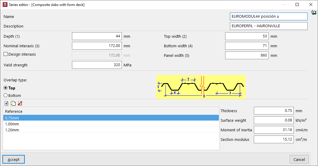
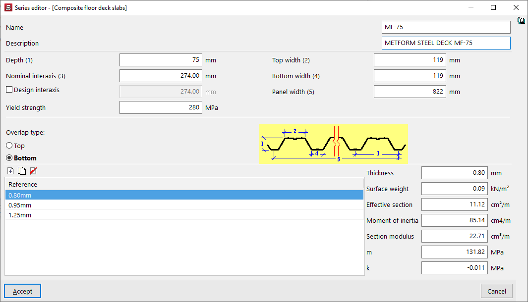
The parameters required to define each type of ribbed sheet are as follows:
- the "Name" and "Description" of the type of badge;
- the parameters that define the geometry of the plate, such as its "Thickness", the "Top width" and the "Bottom width" of each rib, the "Nominal interaxis" between ribs and, optionally, the "Design interaxis", and the total "Panel width";
- the "Yield strength" of steel;
- the "Overlap type" between sheet metal panels, whether at the "Top" or "Bottom";
- and, at the bottom, the list of available sheet thicknesses, with their "Reference"; when selecting each one, the fields on the right allow you to enter the value of the "Thickness" of the sheet, the "Surface weight", the "Moment of inertia" and the "Effective section" of the sheet panel. Furthermore, for composite sheets, the "Section modulus" and the coefficients "m" and "k", provided by the sheet manufacturer, must be specified. To calculate the shear stress, the design value of the ultimate shear stress is determined, and this is partly a function of these coefficients.
Additional options and on-plan insertion
In the "Total depth" field, enter the total depth of the composite slab, including the thickness of the steel sheet and the thickness of the concrete compression layer.
At the bottom of the window, you can define the "Rib direction". These can be:
- "Parallel to a beam" or "Perpendicular to a beam", to be selected by the user;
- Alternatively, "Two reference points" can be marked on the floor plan to define the direction of the beams.
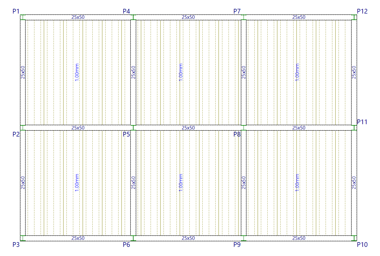
Once you have accepted, moving the cursor over the various closed contours on the plan view will highlight the areas where the panel can be inserted. Then, click the left mouse button to insert the panel into that area.
Finally, using the left mouse button, you must select the beam or the connection points that define the direction of the ribs. The panel will be defined using this data and will be displayed on screen.