
Inserting diagonal bracing
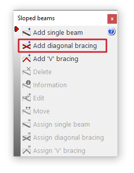
The "Add diagonal bracing" option allows you to enter pairs of diagonal bracing between two points on the floor plan formed by steel sections.
This option is available in the "Sloped beams" menu that appears when you click on the option of the same name in the "Beams" menu, within the "Beam input" tab.
Diagonal bracing data
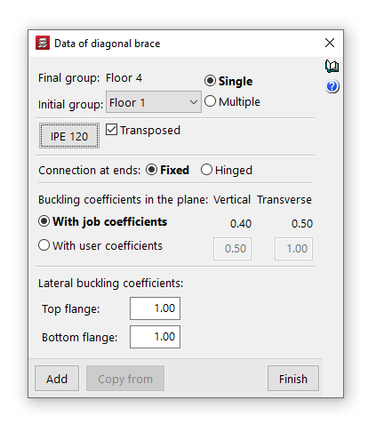
Clicking on the option opens the "Diagonal bracing data" window, where the following parameters are configured:
- Final group, Initial group
In the drop-down menus "Final group" and "Initial group", select the groups of floors where the diagonal bracing start and end. The program does not allow you to select groups in which a group of floors has been defined, as it would not be able to determine on which floor the diagonals end or start. If this is the case, these floors must be ungrouped. On the other hand, it is possible to pass through several intermediate groups of floors. - Single/Multiple
This option is only active if there is a group of plants between the selected final group and initial group, and allows you to select the input mode:- The "Simple" option allows you to enter a single pair of diagonal bracing between the selected end group and initial group of floors.
- The "Multiple" option allows you to enter several pairs of diagonal bracing elements in several groups at once, located in the same position on the floor plan.
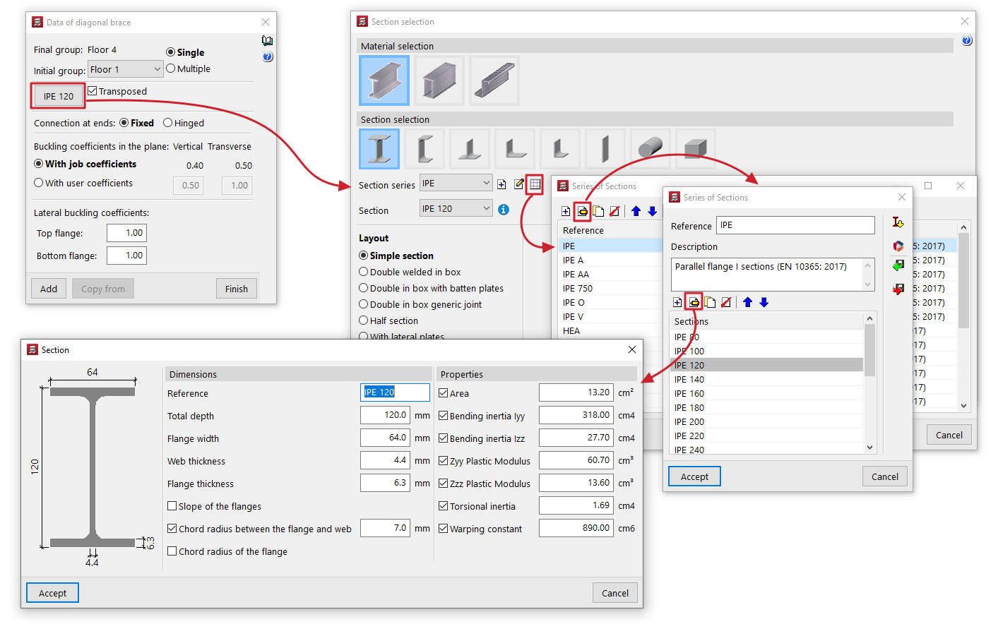
- Material and section selection
The button on the left opens the "Section selection" window, where you can select the material and section of the steel section from those available, including rolled steel sections, reinforced rolled steel sheet sections, and shaped steel sections.- Transposed
The "Transposed" box allows you to rotate the steel sections 90º counterclockwise.
- Transposed
- Connection at the ends
This can be defined as "Bi-potentiometer" or "Bi-articulated". - Buckling coefficients in the vertical and transverse planes
This section allows you to define the buckling coefficients in the "Vertical" and "Transverse" planes of the sections that form the diagonal bracing. You can select "With project coefficients" (as indicated in "Project > Beam options > Buckling coefficients for sloped steel beams and bracing") or "With own coefficients", in which case the user must enter them. - Lateral buckling coefficients
This section allows you to enter the lateral buckling coefficients in the "Top flange" and "Bottom flange" of the sections that form the diagonal bracing.
| Note: |
|---|
| In the case of steel diagonal bracing, to obtain the buckling length of each diagonal bracing, it is considered that the buckling coefficients requested multiply the length between the extreme nodes of the diagonal, i.e. the intermediate node generated by the program at the intersection of bars is not taken into account for this purpose. The vertical and transverse buckling coefficients are established, respectively, in a vertical plane containing the bar and the Z-axis of the structure, and in the transverse plane to this, and not according to the local axes of the bar. |
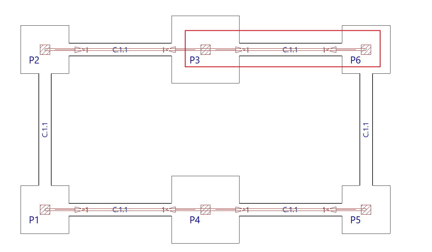
Introduction of diagonal bracing in floor plans
To insert the diagonal bracing, use the left mouse button to mark the starting points of each of the diagonals in the initial group.
Diagonal bracing can have a column as its starting point, so the bases of the columns must be marked in the initial group of diagonals.
| Nota: |
|---|
| At the intersection of the diagonal bracing, the program will generate a rigid node. The diagonals are dimensioned for both tension and compression. Therefore, they may present slenderness problems, as it will be checked that the maximum slenderness defined in the corresponding regulations for elements subjected to compression is not exceeded. |
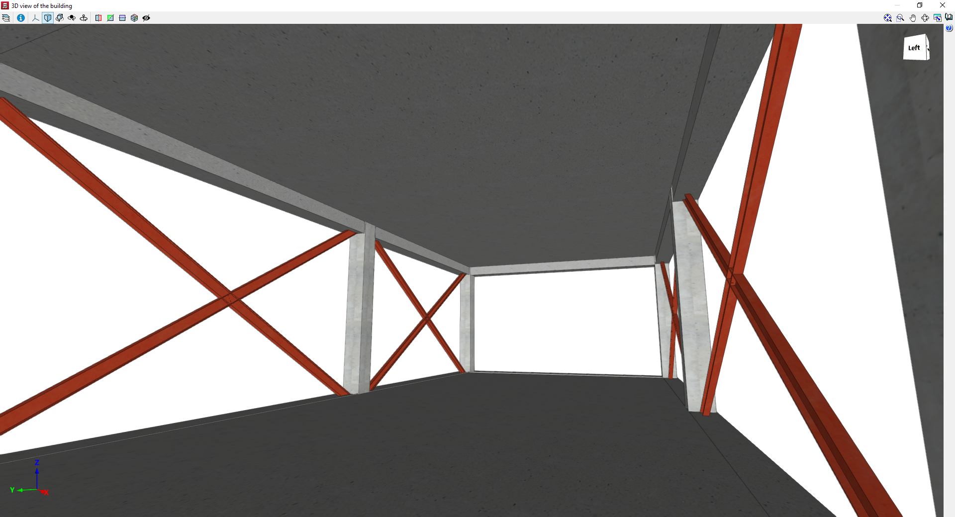
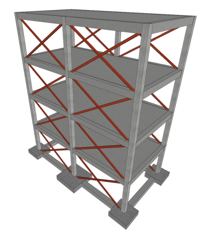
3D views of a model with diagonal bracing