Inserting hollow core slabs
The "Hollow core slab" option, within the "Enter panel" window (accessible via "Slabs > Slab management"), allows you to enter prestressed precast slabs with lightening features or voids (hollow-core slabs).
Selecting hollow core slabs
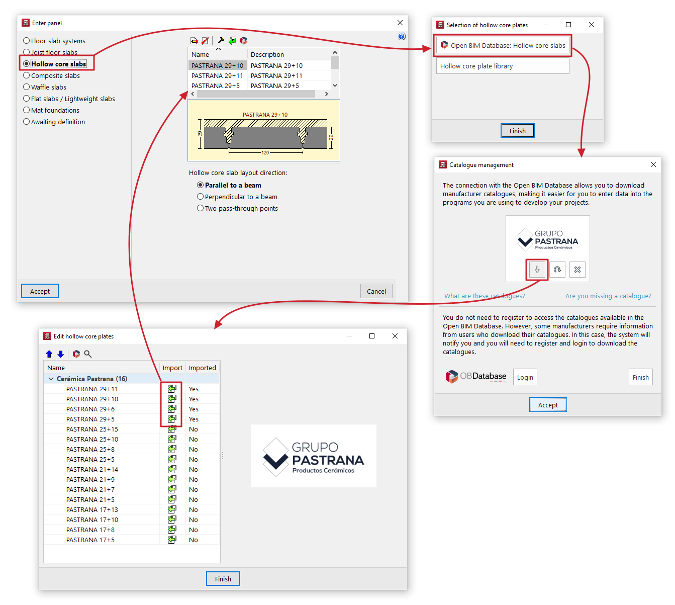
If you check the "Hollow core slabs" option without having previously selected a hollow core slab, the "Selection of hollow core slabs" window will open, displaying two options:
- Open BIM Database: Lightweight panels
This option allows you to download and update hollow core slab manufacturers’ catalogues from the Open BIM Database. When you do so, the "Edit hollow core slabs" window displays a list of products from the downloaded manufacturers, which can be "Imported" one by one into the project by checking the relevant option. When you click on "Finish", the imported manufacturer panels will appear in the panel list in the "Enter panel" window, ready to be selected and added to the model.
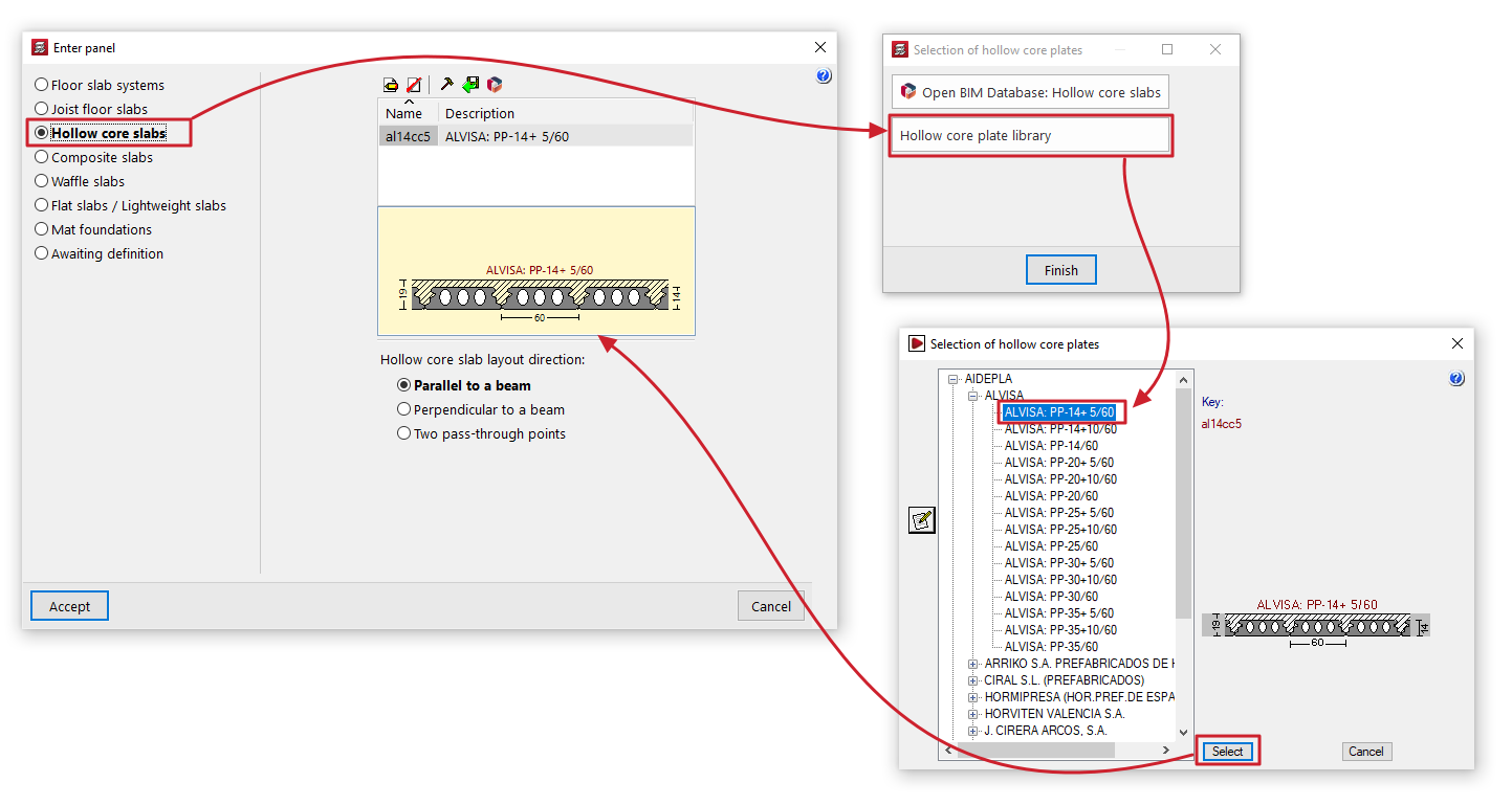
- Hollow core slab library
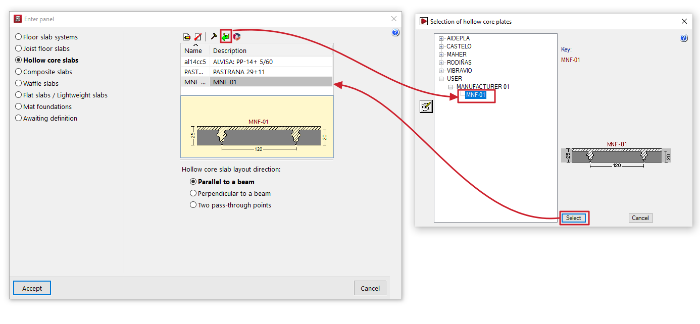
This option opens the "Selection of hollow core slabs" window, which displays the predefined hollow core slab libraries included with the software installation, as well as any user-created hollow core slab libraries.
You can select a panel by expanding the tree to the relevant level. When you select a panel in the tree, the button on the left opens the "Edit hollow core slabs" window, which displays the technical properties of the selected panel. When you click on "Select", the selected panel will appear in the list of panels in the "Enter panel" window, ready to be selected and added to the model.
If panels have already been selected, the program will display a list of available panels in the "Enter panel" window, showing their "Name" and "Description". If you wish to import or create further panels, please use the controls at the top.
Maintenance of hollow core slab libraries
The "Enter panel" window displays a list of available hollow core slabs. The controls at the top of the list allow you to do the following:
- Edit
View the details of the panel selected from the list. For user library boards, you can edit their property values here. - Borrar
Elimina la placa seleccionada de la lista. - Edit library
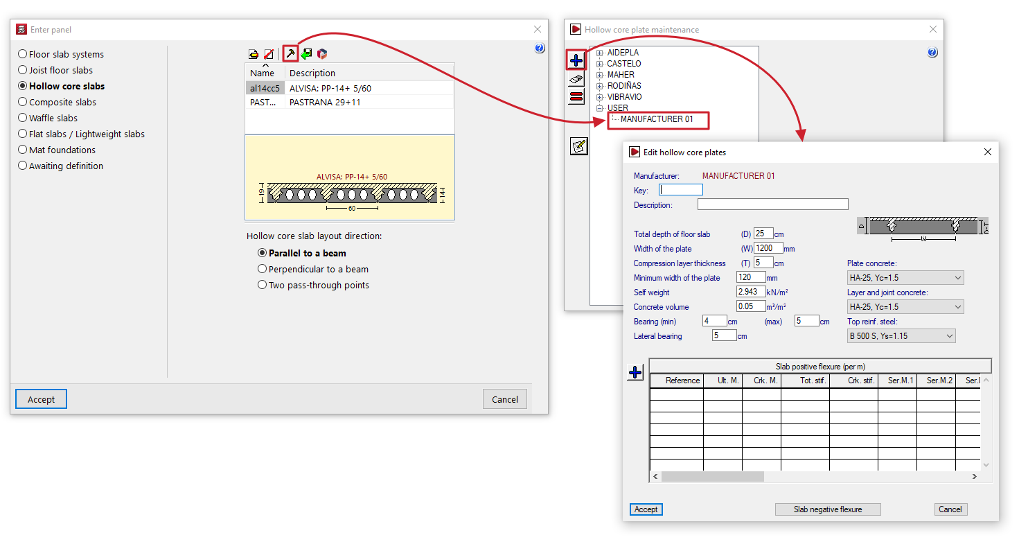
Opens the "Hollow core plate maintenance" window, where you can view the available manufacturer and user hollow core plate libraries. User plate libraries are managed from here:- To create user badges, first select "USER" from the tree and click the "+" button on the left-hand side. This creates an editable user. Next, select this user from the tree and click the "+" button again to create a badge, configuring all its settings.
- You can delete and/or copy user badges by selecting them from the list and using the relevant options on the left-hand side.
- Import from library
Opens the "Selection of hollow core slabs" window. This window displays the manufacturer hollow core slab libraries included in the software installation and the user panel libraries created via "Edit library". You can select any of the panels and click "Select" to import it into the panel list in the "Enter panel" window. - Import from 'Open BIM Database'
Opens the "Editing hollow core slabs" window, which displays the panels from the downloaded Open BIM Database catalogues, with the option to import them into the panel list in the "Enter panel" window.
The "Catalogue management" option at the top of this window allows you to download and update manufacturer catalogues from the Open BIM Database.
Additional options and on plan insertion
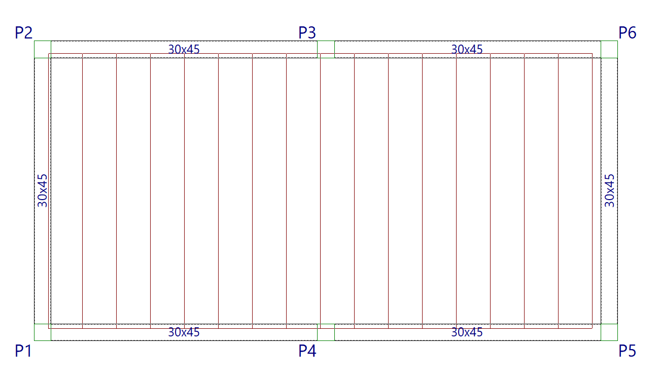
The program will display a designed diagram of the slab selected from the list.
At the bottom of the window, you can specify the "Hollow core slab layout direction". The options are:
- "Parallel to a beam" or "Perpendicular to a beam", to be selected by the user;
- or "Two pass-through points" may be marked on the floor plan to indicate the direction of the panels
Once you have accepted, moving the cursor over the various closed contours on the plan view will highlight the areas where the panel can be inserted. Then, click the left mouse button to insert the panel into that area.
Finally, using the left mouse button, you must select the beam or the connection points that define the direction of the slabs. The slab will be defined using this data and will be displayed on screen.